FANUC MANUAL GUIDE i. OPERATOR’S MANUAL - page 30
INDEX
B-63874EN/05
PARAMETERS FOR MILLING CYCLE
<R>
MACHINING
778
READ AT FIRST
4
Parameters for Milling Cycles in General
778
Reading
261
Parameters for Multi-path Lathe Function
817
Rear End Facing
472, 569
Parameters for Operations in General
748
REAR END FACING BY MILLING
472
Parameters for Pocketing Cycles
787
REAR END FACING BY TURNING
569
Parameters for Program Coordinate System Changing
Registering a New Fixed Form Sentence
236
Function and Tool Offset Memory Changing
REGISTERING FIXED FORM SENTENCES
233
Function
802
Release of Waiting
620
Parameters for the Axial Configuration of the Machine 752
Release Transfer
624
Parameters for Threading Cycles
798
REQUIRED PARAMETERS
744
Parameters for Turning Cycle Machining
797
Restore Group Life
665
PARAMETERS FOR TURNING CYCLE OPTIONS . 795
RESTRICTIONS
249
Parameters Required for Basic Options
744
RESTRICTIONS ON USE
23
Parameters Required for Machining Simulation
745
RETURN TO MENU SCREEN
679
Parameters Required for Other Options except Basic
Return to SETTINGS Menu Screen
679
Option (For Series 30i only)
746
REWINDING A MACHINING PROGRAM
149
PASTE
59
<S>
POCKETING
422
SAFETY PRECAUTIONS
s-1
Position of M Code Output
477
Scaling, Movement, and Other Operations in
PREPARATION
582, 598
Drawing during Machining
165
PREPARING OF THE FIXED FORM SENTENCE
Scaling, Movement, and Other Operations in
MENU
693, 717
Machining Simulation (Animated)
175, 184
PRESETTING RELATIVE COORDINATES
151
Scaling, Movement, and Other Operations in
PROCESS LIST EDITING FUNCTION
597
Machining Simulation (Tool Path)
171, 182
Product Components
17
SCREEN CONFIGURATION
593
PROGRAM COORDINATE SYSTEM CHANGING
SCREEN DISPLAY ITEMS
637, 641
FUNCTION
313
Screen Display Items
650, 652
PROGRAM COORDINATE SYSTEM CHANGING
SCREEN DISPLAY ITEMS
656, 673
FUNCTION AND TOOL OFFSET MEMORY
SCREEN HARD COPY
306
CHANGING FUNCTION
312
SEARCH (FORWARD AND BACKWARD)
57
Program Display Part
595
SEARCHING FOR A MACHINING PROGRAM TO
Program Edit
615
BE EDITED
54
PROGRAM LIST SCREEN
301
SEARHING FOR A SEQUENCE NUMBER IN A
PROGRAM RESTART FUNCTION
156
PROGRAM
150
Program Selection Operation and Other Operations in
Section
25, 29
Drawing during Machining
164
SELECTING A CYCLE MACHINING TYPE
69
Program Selection Operation and Other Operations in
SELECTING A PROGRAM FOR MACHINING
Machining Simulation (Animated)
174, 183
OPERATION
150
Program Selection Operation and Other Operations in
Selecting an Arbitrary Figure Copy Function
140
Machining Simulation (Tool Path)
170, 181
SELECTING FIGURES
73
<Q>
SELECTING THE LIFE MANAGEMENT DATA
[Q TYPE] Soft-key
157
LIST SCREEN
668
i-6
B-63874EN/05
INDEX
SELECTING THE LIFE MANAGEMENT DATA
Settings for Operations in General (All Common Path)
SETTING SCREEN
655
................................................................................773
SELECTING THE SCREEN FOR ASSOCIATING A
Settings for Operations in General (All Common Path) 776
TOOL NUMBER WITH A OFFSET NUMBER
636
Settings for Operations in General (Each Path)
776
SELECTING THE TOOL MANAGEMENT DATA
Settings for Operations in General
SETTING SCREEN
649
(For Multi C Executor)
775
SELECTING THE TOOL NUMBER-BY-TOOL
Settings for Operations in General (For Series 30i)
775
NUMBER TOOL OFFSET SETTING SCREEN ... 640
Settings for Path Colors During Tool Path Plotting
764
SELECTING TOOL DATA AT PROGRAM
Settings for Spindle Status Display
753
ENTERING
257
Settings for Subprogram Selection Screens
756
Selecting Whether to Display the Tool Path or Not in
Settings for the Allocation of Startup Function Keys
765
Drawing during Machining
165
Settings for the Color Palette for Guide Display
761
Set Icon for Selected Turret
583
Settings for the Color Palette for Icon Display
759
SETTING A MAXIMUM PROGRAM SIZE THAT
Settings for the Color Palette for Screen Display
757
CAN BE HANDLED
291
Settings for the Color Palette for Screen Display
SETTING DATA
222
(No.2)
747
Setting for the Display Language
753
Settings for Tool Management Functions
770
SETTING OF DATA FOR ANIMATION
190
Settings for Tool Path Drawing Colors
763
SETTING OF THE TOOL DATA
718
[settings] section
30
SETTING OF TOOL DATA
253, 695
SET-UP GUIDANCE FUNCTIONS
321
SETTING OF TOOL GRAPHIC DATA
258
SHORTCUT FEEDRATE THE MEASUREMENT
SETTING OF TOOL LENGTH OFFSET DATA
713
RESULT SCREEN
273
SETTING OF TOOL OFFSET DATA
252
SHORTCUT FOR STARTING THE CYCLE
Setting of Tool Set
254
CHANGE SCREEN
270
Setting of Tool Type
253
SHORTCUT FOR THE MANUAL MEASUREMENT
SETTING OF WORKPIECE COORDINATE
SCREEN
273
SYSTEM SHIFT DATA
691
SHORTCUT FOR THE TOOL OFFSET SETTING
SETTING OF WORKPIECE ORIGIN OFFSET
SCREEN
272
VALUE
715
SHORTCUT FOR THE WORKPIECE COORDINATE
Setting of X-axis Offset Data
690
SYSTEM SETTING SCREEN
272
Setting of Z-axis Offset Data
688
SHORTCUT FOR VARIOUS SETTING SCREENS...273
SETTING THE LIFE NOTICE FLAG
666
SHORTCUT KEY OPERATIONS
268
SETTING THE WORKPIECE COORDINATE
SHORTCUTS FOR COPY OPERATION
269
DATA
223
SHORTCUTS FOR CUT OPERATION
269
SETTING TOOL OFFSET DATA
228, 687
SHORTCUTS FOR RANGE SELECTION
269
Settings for Arbitrary Figures
771
SHORTCUTS FOR THE ALTER SCREEN FOR
Settings for Arbitrary Figures(XA Plane)
777
REGULAR PROGRAM REGISTRATION
273
Settings for Current Position Display
768
SHORTCUTS FOR THE BASE SCREEN SOFT
Settings for F Load Meter Compensation
769
KEYS
270
Settings for Graphic Display
754
SHORTCUTS FOR THE COMMENT EDITING
Settings for Machining Simulation Animation Colors .. 763
SCREEN
271
Settings for Machining Simulation Axes
755
SHORTCUTS FOR THE CREATION SCREEN FOR
REGULAR PROGRAM REGISTRATION
273
SHORTCUTS FOR THE CYCLE INPUT SCREEN ...272
i-7
INDEX
B-63874EN/05
SHORTCUTS FOR THE FREE FIGURE CREATION
Status Display Part
594
SCREEN
274
SUBPROGRAM TAB ON THE CYCLE FIGURE
SHORTCUTS FOR THE FREE FIGURE INPUT
SELECTION SCREEN
304
SCREEN
274
Support for C-Axis Machining with Rotation Axis
474
SHORTCUTS FOR THE FREE FIGURE MAIN SCREEN
SUPPORT FOR FOLDER MANAGEMENT
................................................................................274
(FOR Series 30i ONLY)
300
SHORTCUTS FOR THE M CODE INSERTION
Support for the Data Server
303
SCREEN
271
SUPPORTABLE MACHINE CONFIGURATION
572
SHORTCUTS FOR THE MENU SELECTION
SYMBOLS USED
12
SCREEN
270
System Variables
260
SHORTCUTS FOR THE PRESET SCREEN
273
<T>
SHORTCUTS FOR THE PROGRAM CREATION
THREADING
559
SCREEN
271
TOOL DATA BASE FUNCTION
251
SHORTCUTS FOR THE PROGRAM LIST SCREEN 271
Tool Graphic Data
258
SHORTCUTS FOR THE REGULAR PROGRAM
TOOL LIFE DATA LIST SCREEN
667
INSERTION SCREEN
270
TOOL OFFSET
643
SHORTCUTS FOR THE REGULAR PROGRAM
TOOL OFFSET DATA WINDOW
318
REGISTRATION SCREEN
272
TOOL OFFSET MEMORY CHANGING
SHORTCUTS FOR THE SEARCH SCREEN
271
FUNCTION
318
SHORTCUTS FOR VARIOUS CONFIRMATION
Tool Path Drawing During Machining and Tool Path
OPERATIONS
269
Machining Simulation
585
Simulation and Actual Working of the Machine
219
Transfer
603
SIMULATION CNC SELECTION
21
TURNING
480, 488
SIMULATOR DEFINITION FILE FORMAT
25
TURNING GROOVING
517
[Simulator_MachineSetting_MaxNumber] section
26
Turret
602
[Simulator_MachineSettingn] section
26
SIMULTANEOUS ALL PATH DISPLAY / EDITING
<U>
FUNCTION
590
UNDO, REDO
61
SLANT FACE MACHINING (COORDINATE
UPDATING LIFE VALUES DISPLAYED ON THE
CONVERSION)
571
TOOL LIFE DATA SCREEN
659
SLANT FACE MACHINING COMMAND
USING TOOL MANAGEMENT DATA
681
(COORDINATE CONVERSION)
573
<V>
[softkey] section
33
Value of M Code Output
476
SOFTWARE
828
VIEWING AND SETTING LIFE MANAGEMENT
Spindle
602
DATA
654
SPINDLE AND STANDBY POSITION TOOL
VIEWING AND SETTING TOOL MANAGEMENT
DISPLAY SCREEN
652
DATA
648
SPINDLE MOVEMENT ANIMATION FOR
VIEWING AND SETTING TOOL OFFSET VALUES639
AUTOMATIC LATHES
217
Start
599
<W>
START AND END OPERATIONS
599
Waiting Line
602
Start Command of Reflection
217
WARNING MESSAGE
267
STARTING BACKGROUND EDITING
241
WORKPIECE SHIFT OFFSET DATA WINDOW
320
STATUS DIPLAY
317
Writing
261
i-8

Revision Record
FANUC MANUAL GUIDE i OPERATOR’S MANUAL (B-63874EN)
Addition of descriptions for Series 30i
Addition of following items
Notes on creating programs, Undo and redo, Arbitrary
figure copy functions, Editing a fixed form figure
04
Dec., 2003
subprogram, Program restart function, Accessing tool
data base function, Memory card input/output of fixed
form sentences, Spindle movement animation for
automatic lathes, Support for folder management
Correction of errors
It is changed to the contents that the whole of the manual
is often understood drastically.
Addition of following items
Changing work coordinate during machining
03
Jul., 2003
simulation, Tool data base function, Editing of free
figure of subprogram form, Multi-path lathe functions,
Modal display of offset types, Example of
programming, and Manual guide i setup method
Correction of errors
Addition of following items
Displaying the drawing-during-machining window, BG
editing, NC statement conversion, Next-block display
function,
Operations in background editing,
Operations with the NC statement conversion function,
Shortcut key operations, Help screen, Memory card
input/output function, Handling large programs,
02
Jan., 2003
Fixed-point format calculation function, Automatic
setting of initial value data, Rear end facing by milling,
Subspindle-based c-axis machining, Rear end facing
by turning hole machining
(workpiece rotation),
Required parameters, Parameters common to lathing
cycles, Parameters for machining simulation
(animated)
Correction of errors
Addition of following items
Machining time display, Prism blank figure, XA plane,
MANUAL GUIDE i Simulator for PC
01
Aug., 2002
05
Jul., 2004
Correction of errors
Edition
Date
Contents
Edition
Date
Contents
Series 16i /18i /21i - MB/TB MANUAL GUIDE i
Addition of supplemental instructions into an Operator’s Manual
1.Type of applied technical documents
Name
FANUC MANUAL GUIDE i
Operator’s Manual
Spec. No./Ed.
B-63874EN/05
2.Summary of Change
Group
Name/Outline
New, Add,
Applicable
Correct,
Date
Delete
Basic
Function
Optional
VII. Supplemental Instructions
Add
Immediately
Function
Unit
Maintenance
Parts
Notice
Correction
Another
FANUC MANUAL GUIDE i
Name
(Series16i/18i/21i-MB/TB)
OPERATOR’S MANUAL
01
05.03.28
Newly registered
Draw.
B-63874EN/05-1
Ed.
Date
Design
Description
Page
1/100
FANUC LTD.

VII. SUPPLEMENTAL INSTRUCTIONS
FANUC MANUAL GUIDE i
Name
(Series16i/18i/21i-MB/TB)
OPERATOR’S MANUAL
Draw.
B-63874EN/05-1
Ed.
Date
Design
Description
Page
2/100
FANUC LTD.

1
Outline
Various functions described in this Part VII are available from the
version 06 of MANUAL GUIDE i for Series16i/18i/21i.
As to the version 05 and before it, refer to the other Parts. In case of that
there is overlapping part between this Part and other Parts, the content
described in this Part becomes available if you are using the version 06.
The version number on MANUAL GUIDE i for Series30i and Series 0i is
as follows.
For Series30i, the version is 08.
For Series 0i, the version is 02.
FANUC MANUAL GUIDE i
Name
(Series16i/18i/21i-MB/TB)
OPERATOR’S MANUAL
Draw.
B-63874EN/05-1
Ed.
Date
Design
Description
Page
3/100
FANUC LTD.
2
Display Attribute of Binary File (Only FS30i)
2.1.
Details
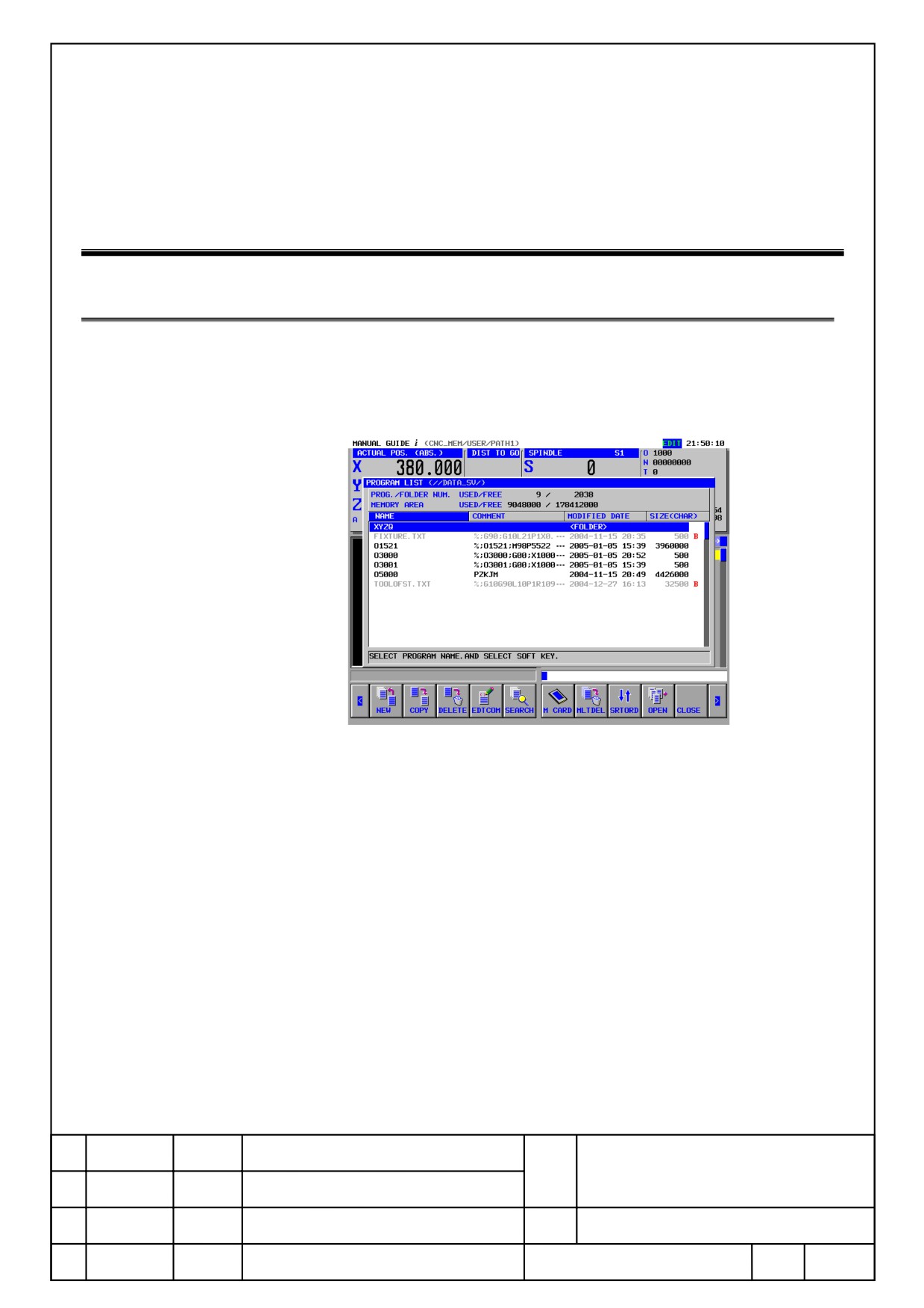
On program list window, if there is a file other than program (hereinafter
call Binary File) on data server, the file is displayed in gray character, and
shows a letter “B” in red at very right on a screen as a figure below.
FANUC MANUAL GUIDE i
Name
(Series16i/18i/21i-MB/TB)
OPERATOR’S MANUAL
Draw.
B-63874EN/05-1
Ed.
Date
Design
Description
Page
4/100
FANUC LTD.
3
Alter the Cursor Position After the Copy
3.1.
Details
NEW
O LIST
↑SRCH
↓SRCH
OSRCH
COPY
CUT
DELETE
KEYPST
PASTE
PROG
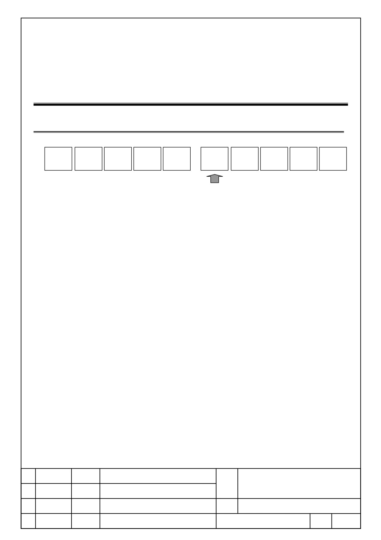
By pressing [COPY] to display a message of copy range selection, press
[COPY] after selecting the range by cursor key. (Displays in yellow) Copied
contents are saved to clipboard.
After operated copy, whether return a cursor to the top block of a selected
range, or keep a cursor to the end block of a selected range, are depending
on a setting of below parameter.
Parameter No.14705#1=0:Return a cursor to the top block of a selected
range.
Parameter No.14705#1=1:Keep a cursor to the end block of a selected
range.
FANUC MANUAL GUIDE i
Name
(Series16i/18i/21i-MB/TB)
OPERATOR’S MANUAL
Draw.
B-63874EN/05-1
Ed.
Date
Design
Description
Page
5/100
FANUC LTD.

4
Maximum Characters in a Block
4.1.
Details
On MANUAL GUIDE i, program containing over 199 characters cannot be
operated.
When selecting a program containing over 200 characters (including spaces),
message ”Block exceed maximum size” is displayed, and all operations
cannot be performed.
When the message is displayed, please select another program on NC
screen.
FANUC MANUAL GUIDE i
Name
(Series16i/18i/21i-MB/TB)
OPERATOR’S MANUAL
Draw.
B-63874EN/05-1
Ed.
Date
Design
Description
Page
6/100
FANUC LTD.

5
Specify Side Finish Feedrate of Free Figure
at Milling
5.1.
Outline
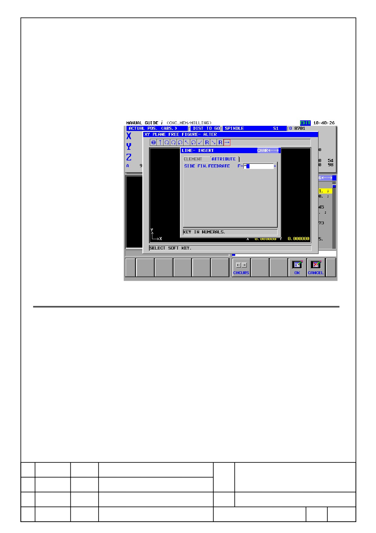
On free figure at milling, side finish feed rate per element can be set. This
function is available with setting parameter No27002<#4> = 1.
When side finish feed rate is available, side finish federate at
[ATTRIBUTE] tab of figure element indicate as following plane
●
XY FREE FIGURE BLOCK
・Line:
G1201
・Arc(CW): G1202
・Arc (CCW): G1203
・Chamfer: G1204
・Corner R: G1205
●
YZ FREE FIGURE BLOCK
・Line:
G1301
・Arc(CW): G1302
・Arc (CCW): G1303
・Chamfer: G1304
・Corner R: G1305
●
XC FREE FIGURE BLOCK
・Line:
G1501
・Arc(CW): G1502
・Arc (CCW): G1503
・Chamfer: G1504
・Corner R: G1505
●
ZC FREE FIGURE BLOCK
・Line:
G1601
・Arc(CW): G1602
・Arc (CCW): G1603
・Chamfer: G1604
・Corner R: G1605
FANUC MANUAL GUIDE i
Name
(Series16i/18i/21i-MB/TB)
OPERATOR’S MANUAL
Draw.
B-63874EN/05-1
Ed.
Date
Design
Description
Page
7/100
FANUC LTD.
● XA FREE FIGURE BLOCK
・Line:
G1701
・Arc(CW): G1702
・Arc (CCW): G1703
・Chamfer: G1704
・Corner R: G1705
5.2.
Machining Type Side Finish Feed Rate is Available
When a value [Side Finish Feed Rate] is set, it is cut by [Side Finish Feed
Rate] instead of [Single Cut Feed Rate] set by machining type block on cut
feed rate used [Single Cut Feed Rate].
At this event, the available cycles to set a side finish federate are as
followings.
● CONTOURING
・Outer Wall Side Finishing (G1062)
・Inner Wall Side Finishing (G1066)
・Partial Side Finishing (G1070)
● EMBOSSING
・Side Finishing (G1082)
FANUC MANUAL GUIDE i
Name
(Series16i/18i/21i-MB/TB)
OPERATOR’S MANUAL
Draw.
B-63874EN/05-1
Ed.
Date
Design
Description
Page
8/100
FANUC LTD.

However, [Side Finish Feed Rate] cannot be specified on blank figure of
embossing (figure type of start point element is concave free figure at
embossing). Input item [Side Finish Feed Rate] is also not displayed.
● Pocketing
・Side Finishing (G1042)
● Grooving
・Side Finishing (G1052)
5.3.
Output Side Finish Feed Rate
When output a program of figure element, entered value to [Side Finish
Feed Rate] is output as a following format continuing to address F.
When [Side Finish Feed Rate] is “blank”, address F is not output.
(Example of line of XY plane)G1201 H-10. V-20. K5. C-10. L0. M0. F50. ;
Element that a setting value [Side Finish Feed Rate] is “0” or ”blank”, it is
cut by a value [Single Cut Feed Rate] which is set by machining type block.
5.4.
Number of Finishing
[Side Finishing] at contouring and grooving, [Cut Number (cut number at
finishing)] is possible to set, and [Side finish feed rate] is available at each
cutting.
5.5.
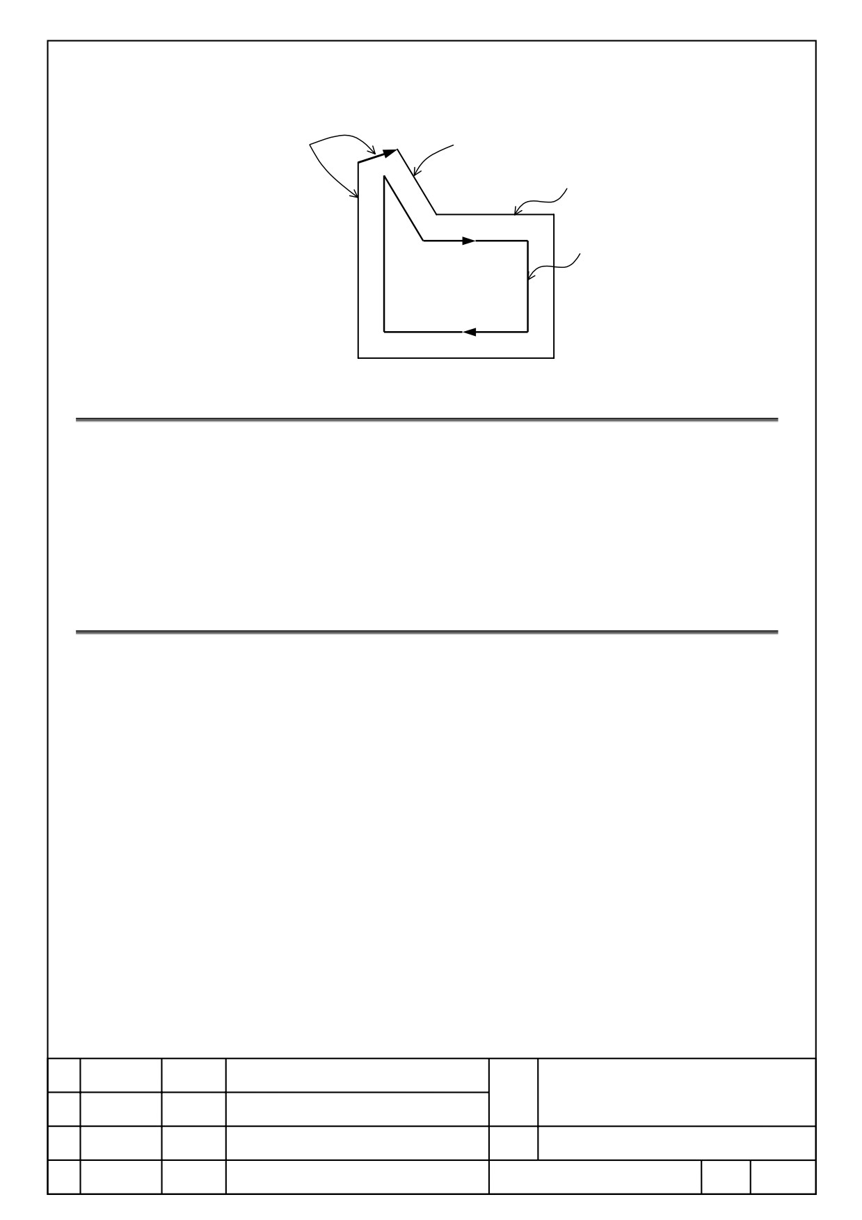
Feed Rate of Block Added when Machining
When programming a figure of acute angle as figure below, in some case a
new block is added for route of tool at a corner of acute angle. At this
event, a feed rate of added block is set as a federate specified at element
right before creating a figure. For example, when f1 is set for a value [Side
Finish Feed Rate] to program figure block N1 as the figure below, a feed
rate of added block n is set to f1.
FANUC MANUAL GUIDE i
Name
(Series16i/18i/21i-MB/TB)
OPERATOR’S MANUAL
Draw.
B-63874EN/05-1
Ed.
Date
Design
Description
Page
9/100
FANUC LTD.
n
f1
f2
Tool Path
N2
Program Figure and Create
N1
Direction
5.6.
Figure Copying
When operating a figure copy, a value of [Side Finish Feed Rate] of copied
parts element is set “blank”. When [Side Finish Feed Rate] is need to set,
alter by entering a value at [Alter] soft key at free figure entry screen.
At a figure copy, it is converted that a corner is for element of arc, and
chamfering is for element of line. At this time, a value of [Side Finish Feed
Rate] is set to “blank”.
5.7.
NC Program Conversion
At NC program conversion, a value specified to [Side Finish Feed Rate] at
converted cutting block is output continued by address F.
When a setting value of [Side Finish Feed Rate] is set to “0” or “blank”, a
value of [Single Cut Feed Rate] is output.
FANUC MANUAL GUIDE i
Name
(Series16i/18i/21i-MB/TB)
OPERATOR’S MANUAL
Draw.
B-63874EN/05-1
Ed.
Date
Design
Description
Page
10/100
FANUC LTD.
6
Specify Semi Finish Feed Rate of Free Figure
for Turning (ZX Plane)
6.1.
Outline
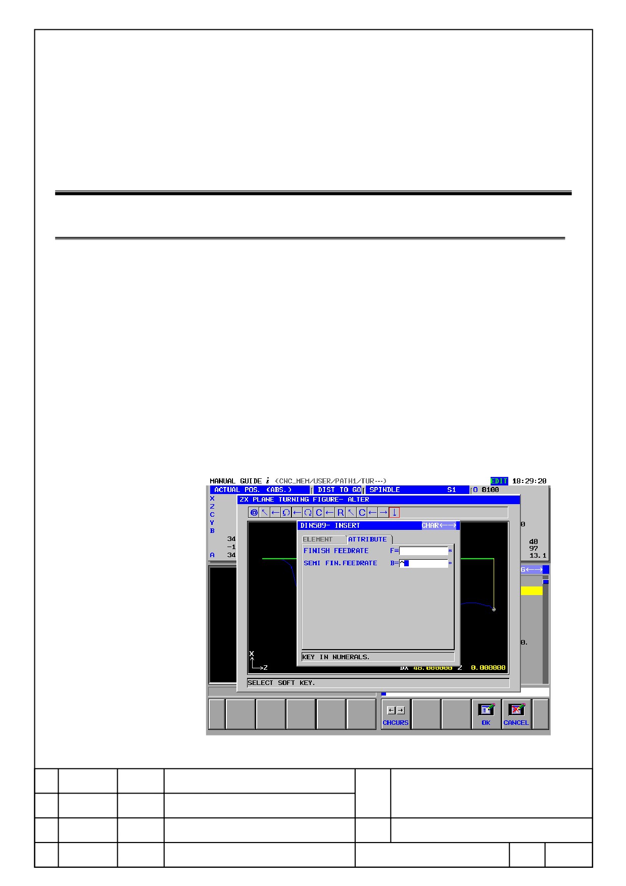
On free figure at turning, semi finish feed rate per element can be set. This
function is available with setting parameter No27102<#4> = 1. When semi
finish feed rate is available, semi finish feed rate at 2nd row of [Attribute]
tab of the following figure element or necking figure are displayed.
・Line
G1451
・Arc(CW)
G1452
・Arc(CCW)
G1453
・Chamfer
G1454
・Corner R
G1455
・DIN509
・DIN509F
・DIN76
FANUC MANUAL GUIDE i
Name
(Series16i/18i/21i-MB/TB)
OPERATOR’S MANUAL
Draw.
B-63874EN/05-1
Ed.
Date
Design
Description
Page
11/100
FANUC LTD.

6.2.
Machining Type that Semi Finish Feed Rate is Available
Cycle that setting of semi finish feed rate is available.
・Outer Semi Finishing
G1123
・Inner Semi Finishing
G1124
・Face Semi Finishing
G1125
6.3.
Output a Program of Semi Finish Feed Rate
When output a program of figure element, a value entered to [Semi Finish
Feed Rate] of figure element is output as a following format continuing to
address B. When a value of [Semi Finish Feed Rate] is “0” or ”blank”,
address B is not output.
(Example:If it is a line. G1451 H-2. V17.5 K4. D17.5 A45. L0. M0. T1.
Bxx ;)
When element that a setting value of [Semi Finish Feed Rate] is “0” or
“blank”, it is cut by [Feed Rate] specified at machining block of semi
finishing.
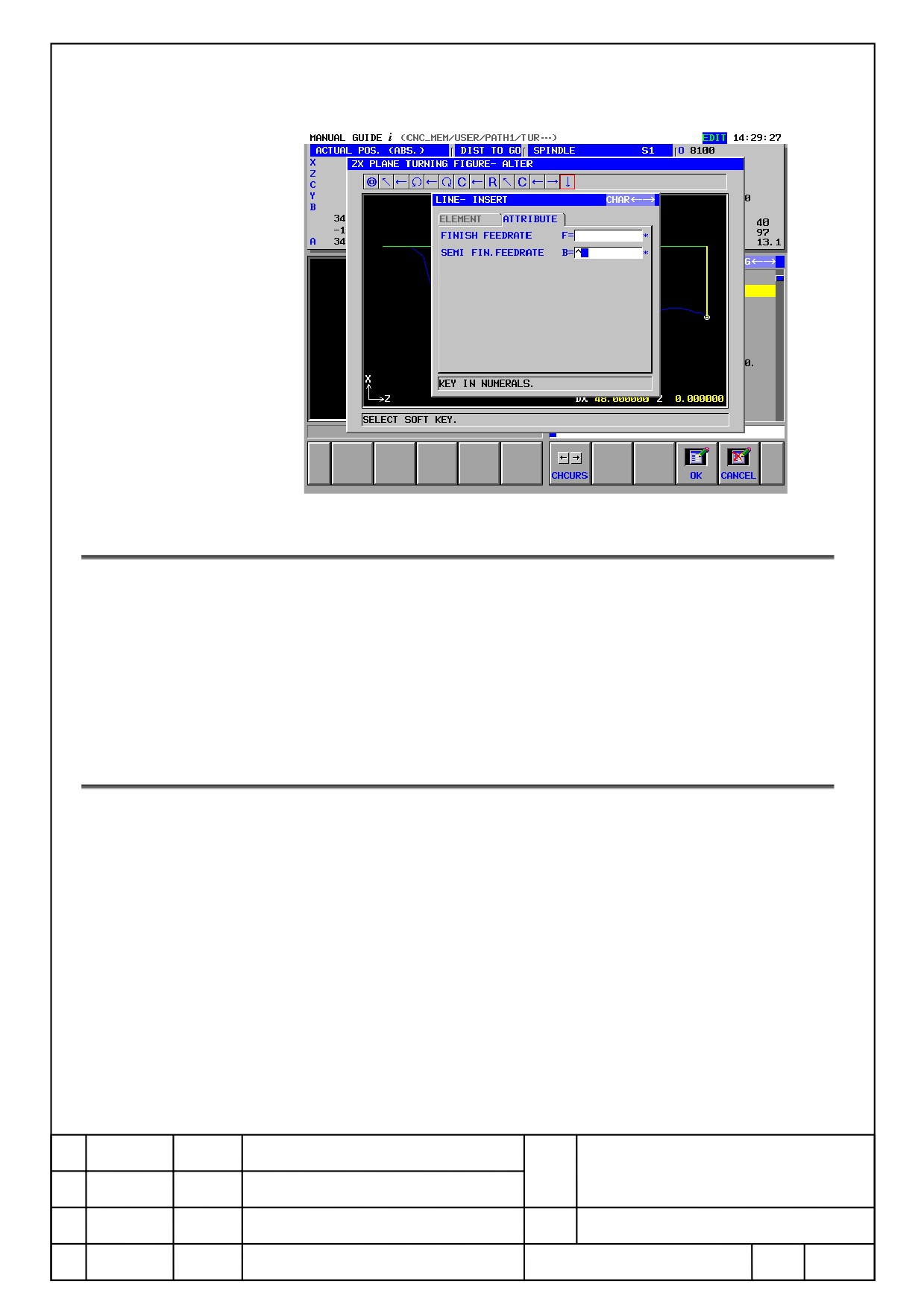
6.4.
Necking Figure
As the same as figure element, semi finish feed rate can set at [Element
Attribute] of necking figure. Set value is automatically entered the same
value to each element (Line, Arc, Corner R). At free figure entry screen,
open an element created by soft key [Alter] to change the setting value.
FANUC MANUAL GUIDE i
Name
(Series16i/18i/21i-MB/TB)
OPERATOR’S MANUAL
Draw.
B-63874EN/05-1
Ed.
Date
Design
Description
Page
12/100
FANUC LTD.
6.5.
Figure Copying
When operating a figure copy, a value of [semi finish feed rate] of copied
part element is set “blank”. When [semi finish feed rate] is required to set,
change the value by a soft key [Alter] at free figure entry screen.
At figure copy, corner R is converted to an element of arc, chamfering is
converted to line element. At this event, a value of [semi finish feed rate] is
set to “blank”.
6.6.
NC Program Conversion
On NC program conversion, a value specified at [Semi Finish Feed Rate] at
converted cutting block is output continuing to address F.
When set value of [Semi Finish Feed Rate] is set to “0” or “blank”, a value of
[Feed Rate] set at machining block of semi finishing is output.
FANUC MANUAL GUIDE i
Name
(Series16i/18i/21i-MB/TB)
OPERATOR’S MANUAL
Draw.
B-63874EN/05-1
Ed.
Date
Design
Description
Page
13/100
FANUC LTD.
7
Specify a Griding Amount of Free Figure
for Turning (ZX Plane)
7.1.
Outline
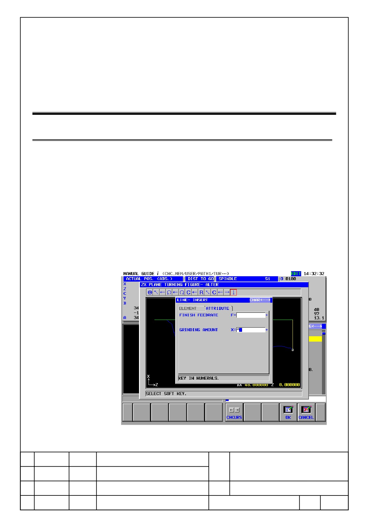
At a free figure for turning, grinding amount can be set per element. This
function is available by setting a parameter No.27102<#3> is set to “1”.
When a grinding amount is available, Input item of grinding amount is
displayed at 3rd row of [Attribute] tab of figure element listed below. At
turning grooving, input item of grinding amount is displayed; however, the
entered grinding amount is invalid.
・Line
G1451
・Arc (CW)
G1452
・Arc (CCW)
G1453
・Chamfer
G1454
・Corner R
G1455
FANUC MANUAL GUIDE i
Name
(Series16i/18i/21i-MB/TB)
OPERATOR’S MANUAL
Draw.
B-63874EN/05-1
Ed.
Date
Design
Description
Page
14/100
FANUC LTD.

7.2.
Machining Grinding Amount is Available
Cycle that a setting of grinding amount is available.
・Outer Roughing
G1120
・Inner Roughing
G1121
・Face Roughing
G1122
・Outer Semi Finishing
G1123
・Inner Semi Finishing
G1124
・Face Semi Finishing
G1125
・Outer finishing
G1126
・Inner finishing
G1127
・Face finishing
G1128
7.3.
Output a Program of Grinding Amount
When output a program of figure element, a value entered to [Grinding
Amount] is output by a following format continuing to the address X. When
a value of [Grinding Amount] is set “blank”, address X is not output.
(Example:When Line G1451 H-2. V17.5 K4. D17.5 A45. L0. M0. T1.
Xxx ; )
7.4.
Unit of Grinding Amount and Setting Range
Setting unit is input unit. Value of setting range is as follows.
IS-A: -999999.99~999999.99mm, -99999.999~99999.999inch
IS-B: -99999.999~99999.999mm, -9999.9999~9999.9999inch
IS-C: -9999.9999~9999.9999mm, -999.99999~999.99999inch
IS-D: -999.99999~999.99999mm, -99.999999~99.999999inch
IS-E: -99.999999~99.999999mm, -9.9999999~9.9999999inch
7.5.
Use with a Finish Amount Specified at Machining Block.
When [Grinding Amount] is set, a specified value is reflected and corrected
to the last part figure. Machining cycle considered a value of [X axis
direction Finish Amount] and [Z axis direction Finish Amount] specified at
machining block for corrected last part figure.
FANUC MANUAL GUIDE i
Name
(Series16i/18i/21i-MB/TB)
OPERATOR’S MANUAL
Draw.
B-63874EN/05-1
Ed.
Date
Design
Description
Page
15/100
FANUC LTD.

7.6.
Necking Figure Inputting
At necking figure, [Grinding Amount] is not specified. However created
necking figure is spread for matching element of line, arc, and corner R, and
it is possible to input [Grinding Amount] by opening an element spread by
soft key [Alter] at free figure entry screen.
7.7.
Figure Copying
When operating a figure copy, a value of [Grinding Amount] of copied part
element is set “blank”. When it is required to set, input a value by soft key
[Alter] at free figure entry screen to change. At figure copy, chamfering is
converted to line element; however, a value of [Grinding Amount] is set
“blank”.
7.8.
Direction that Grinding Amount is Available
Direction of specified [Grinding Amount] is a normal direction of each
element.
FANUC MANUAL GUIDE i
Name
(Series16i/18i/21i-MB/TB)
OPERATOR’S MANUAL
Draw.
B-63874EN/05-1
Ed.
Date
Design
Description
Page
16/100
FANUC LTD.
8
Combining Tool Databese and
Tool Management Function
When a option of tool management function is available, data table on tool
management function can be displayed at MANUAL GUIDE i screen. In
this instance, setting screen of tool database is added to the table of tool
management function.
NOTE
1 The option of tool management function is needed to use this
function.
2 This function is available by setting a parameter No.14705#5 = 1
3 Please refer [A-78614 Specifications of Tool Management Function ]
for details of tool management function.
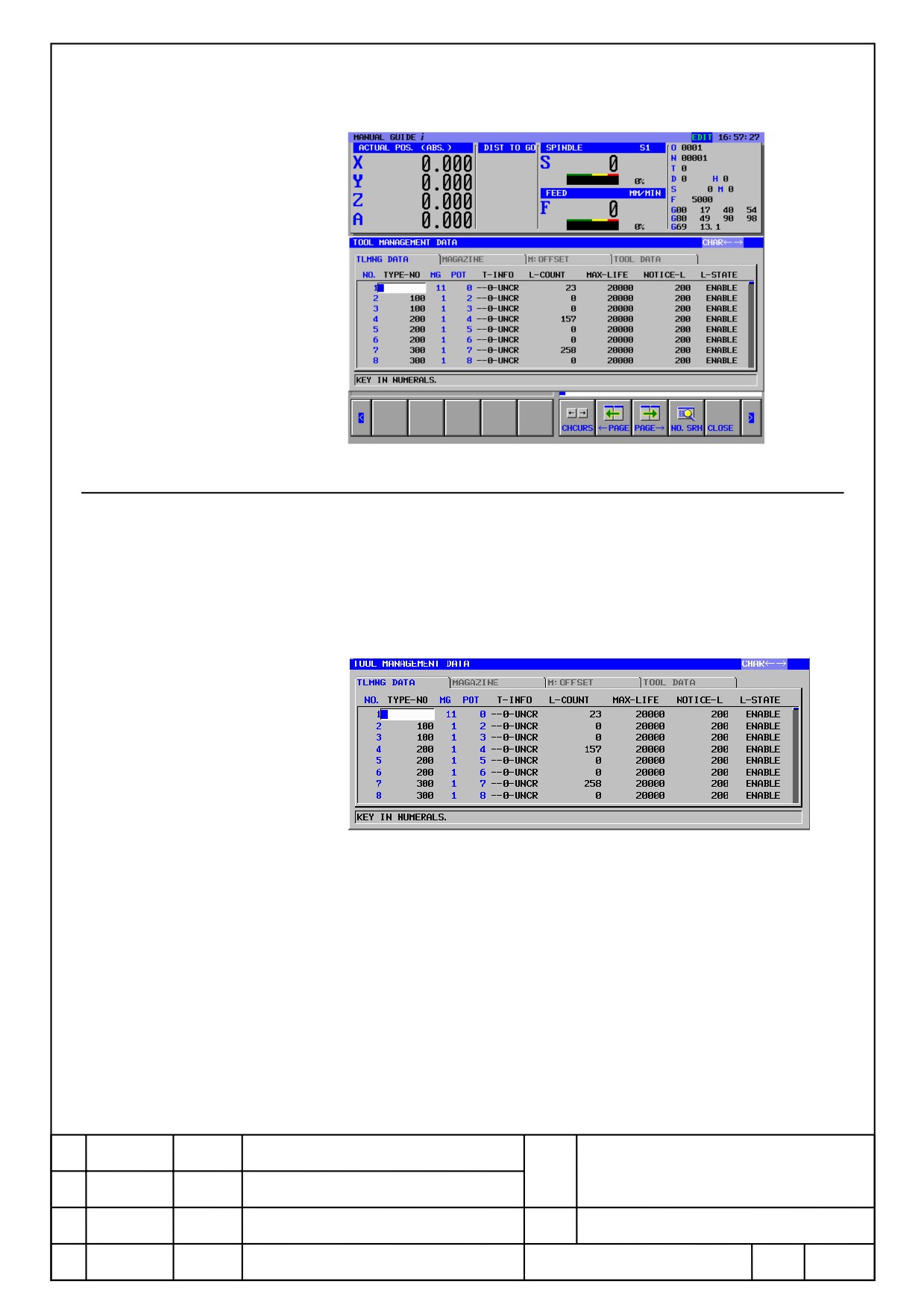
8.1.
Setting of Tool Management Data
8.1.1
Tool Management Data Screen
Press [TOOL] to display tool management data window.
In this window, all of tool management data, magazine data, tool offset and
tool data can be set.
G-CONT
UNDO
REDO
WK SET
TOOL
SETING
FANUC MANUAL GUIDE i
Name
(Series16i/18i/21i-MB/TB)
OPERATOR’S MANUAL
Draw.
B-63874EN/05-1
Ed.
Date
Design
Description
Page
17/100
FANUC LTD.
8.1.2
Tool Management Data Tab
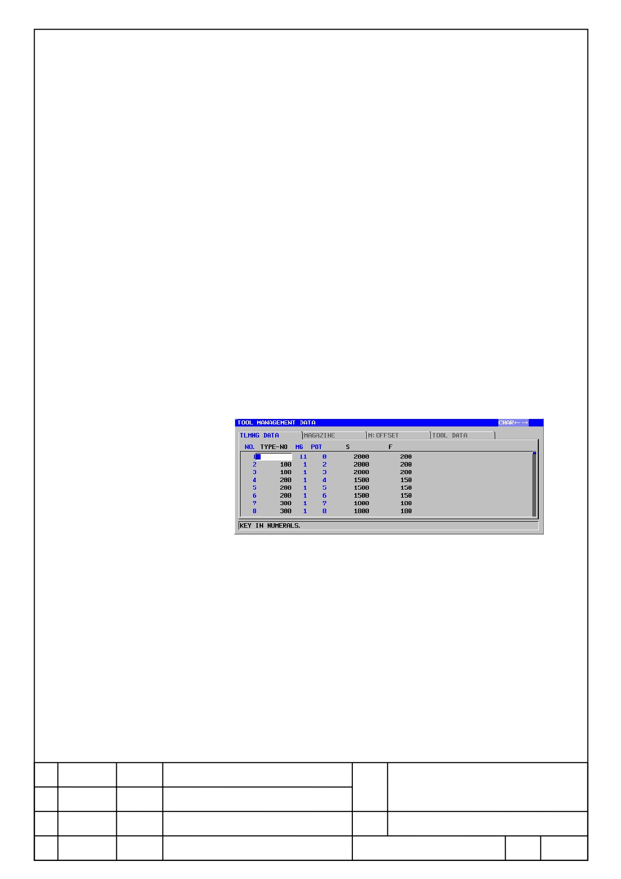
At the tool data management data tab, offset number, life state, spindle
speed, feedrate, customize information and tool information are possible to
set.
At the below screen, life state can be set.
The following data are possible to set.
NO.(Tool Management Data Number)
Display a tool kind number(T code). It only displays, and cannot be set.
TYPE-NO
Display a tool type number(T code).
MG(Magazine Number)
Indicate a magazine number. It only displays, and cannot be set.
POT
Indicate a pot number. It only displays, and cannot be set.
T-INFO
Indicate the 6 kind of information listed below in order from the right.
FANUC MANUAL GUIDE i
Name
(Series16i/18i/21i-MB/TB)
OPERATOR’S MANUAL
Draw.
B-63874EN/05-1
Ed.
Date
Design
Description
Page
18/100
FANUC LTD.
2 bit from the left are not used.
・Tool Management Data
:Enable(R)/Unable(-)
・Life Count Type
:Time(T)/Count(C)
・Tool Type
:Large diameter tool(B)/Regular Tool(N)
・Access to the Data
:Locked(L)/Unlocked(U)
・Include / exclude a subject for search when Life State [Unable]
:
Include(-)/Exclude(S)
・Life Count cycle
:1 second(0)/8 millisecond(1)
L-COUNT
Count used a tool / time is displayed.
MAX-LIFE
Maximum tool life / time is displayed.
NOTICE-L
Notice life value of a tool / time is displayed.
L-STATE
Current condition of a tool is displayed.
4 conditions of NO-MNG, ENABLE, OVER and DAMAGE are displayed.
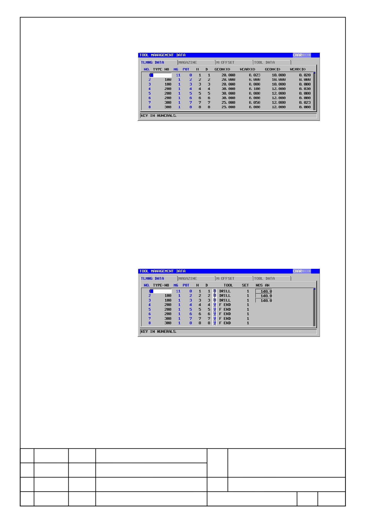
Pressing [←PAGE] or [PAGE→] several times to display the following
spindle rotation number or setting screen of feed rate are displayed.
The following data can be set.
S(Spindle Speed)
Display a spindle speed.
F(Feedrate)
Display a feedrate.
Press [←PAGE] or [PAGE→] several times, the following setting screen of
tool offset is displayed.
FANUC MANUAL GUIDE i
Name
(Series16i/18i/21i-MB/TB)
OPERATOR’S MANUAL
Draw.
B-63874EN/05-1
Ed.
Date
Design
Description
Page
19/100
FANUC LTD.
The following data is possible to set.
H(Tool Length Compensation Number), D(Tool Diameter Compensation
Number)
Tool length compensation number and tool diameter compensation
number are displayed. It does not display on lathes.
TG(Geometry offset Number), TW(Wear offset Number)
Tool geometry compensation number and tool wear offset number are
displayed. It does not display on machining centers.
Figure, Wear
Offset value of compensation number set to H, D, TG and TW are
displayed.
Press [←PAGE] or [PAGE→] several times to display a setting screen of the
following tool information is displayed.
Refer a chapter of tool database function for details of data contents.
Press [←PAGE] or [PAGE→] several times to display the following setting
screen of customize data.
FANUC MANUAL GUIDE i
Name
(Series16i/18i/21i-MB/TB)
OPERATOR’S MANUAL
Draw.
B-63874EN/05-1
Ed.
Date
Design
Description
Page
20/100
FANUC LTD.
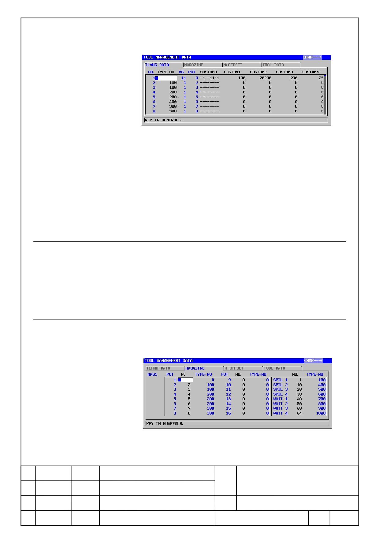
The following data can be set.
CUSTOM 0
Customize information by bit type
1 or 0 is possible to enter per bit
CUSTOM 1~4
Customize information
CUSTOM 5~20
Customize information. Displayed only when a option of adding
customize data of tool management function is available.
8.1.3
Customize of Tool Management Data Display
Changing displaying position of screen element at tool management data
screen(Type Number, Tool Information, and Life Counter etc.), or selection
of display/ undisplay is possible to operate.
Refer [A-78614 Tool Management Function specifications manual] for
details.
8.1.4
Magazine Management Table Tab
At magazine data tab, tool management data number and tool type number
corresponding to pot of magazine, spindle, and wait position are displayed.
POT
Pot number is displayed.
FANUC MANUAL GUIDE i
Name
(Series16i/18i/21i-MB/TB)
OPERATOR’S MANUAL
Draw.
B-63874EN/05-1
Ed.
Date
Design
Description
Page
21/100
FANUC LTD.

NO.
Display a tool management data number.
TYPE-NO.
Tool type number corresponding to tool management data number is
displayed.
SPDL
Tool management number of spindle position and tool type number are
displayed.
WAIT
Tool management number of wait position and tool type number are
displayed.
8.1.5
Tool Data Tab
Display a tool information screen.
Operation is the same as existing tool data screen.
8.1.6
Tool Offset Tab
Display tool offset screen.
Operation is the same as tool offset screen.
8.2.
Memory card Input / Output
By following a below operation, it is possible to input / output tool
management data to memory card at MANUAL GUIDE i screen.
8.2.1
Output Tool Management Data
Follow a below operation to output tool management data.
(1) Select EDIT mode on machine control board. And display a screen of
tool management function.
(2) After display a tool management function screen by pressing [Tool] and
[<] or [>] is pressed several times, the following soft key is displayed.
OUTPUT
INPUT
CLOSE
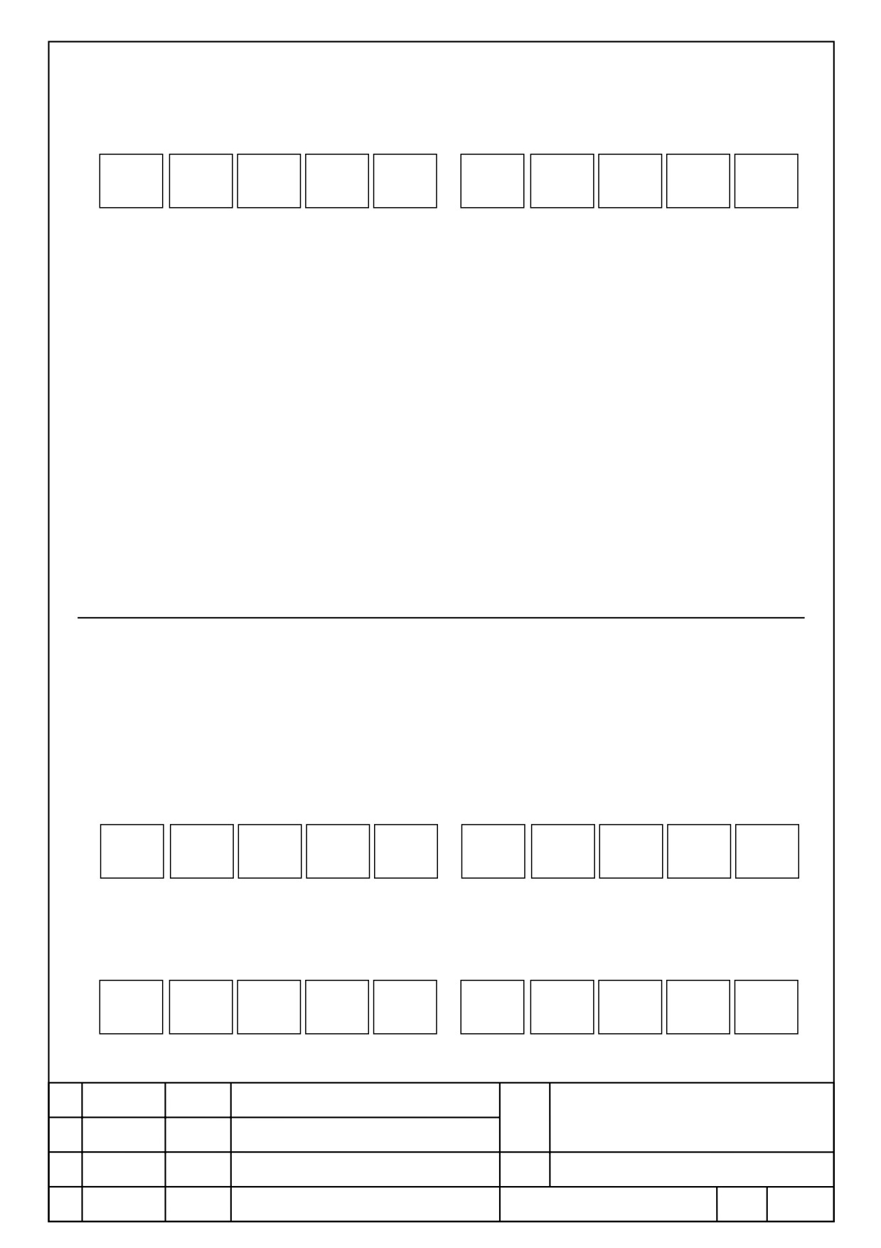
(3) A below softkey row is displayed by pressing [Output], and output data
can be select.
FANUC MANUAL GUIDE i
Name
(Series16i/18i/21i-MB/TB)
OPERATOR’S MANUAL
Draw.
B-63874EN/05-1
Ed.
Date
Design
Description
Page
22/100
FANUC LTD.
TOOL
MAG
STATUS
CSTM
DISPCT
P- NAME
POINT
CANCEL
[TOOL] : Output a tool management data and tool database data.
[MAG] : Output a data of magazine management table.
[STATUS] : Output a name data of tool life status.
[CSTM] : Output a name data of customize data
To display the following 3 items, an option of tool management function
expansion is required.
[DISPCT] : Output screen customize data.
[P-NAME] : Output a name data of spindle/wait position.
[POINT] : Output a position of decimal point of customize data.
(4) After pressing a soft key of tool management data that you want to
output, check message is disaplayed. Press [Yes ] to output tool
management data they are output to memory card.
8.2.2
Input Tool Management Data
To input tool management data, follow the operation below.
(1) Select edit mode by control panel to display the screen of tool
management function.
(2) Press [TOOL] to display the tool management function screen, and
press[<] or [>] several times to display the below softkey.
OUTPUT
INPUT
CLOSE
(3) press [INPUT] to display a below soft key row, and input data can
select.
TOOL
MAG
STATUS
CSTM
DSPCT
P- NAME
POINT
CANCEL
FANUC MANUAL GUIDE i
Name
(Series16i/18i/21i-MB/TB)
OPERATOR’S MANUAL
Draw.
B-63874EN/05-1
Ed.
Date
Design
Description
Page
23/100
FANUC LTD.
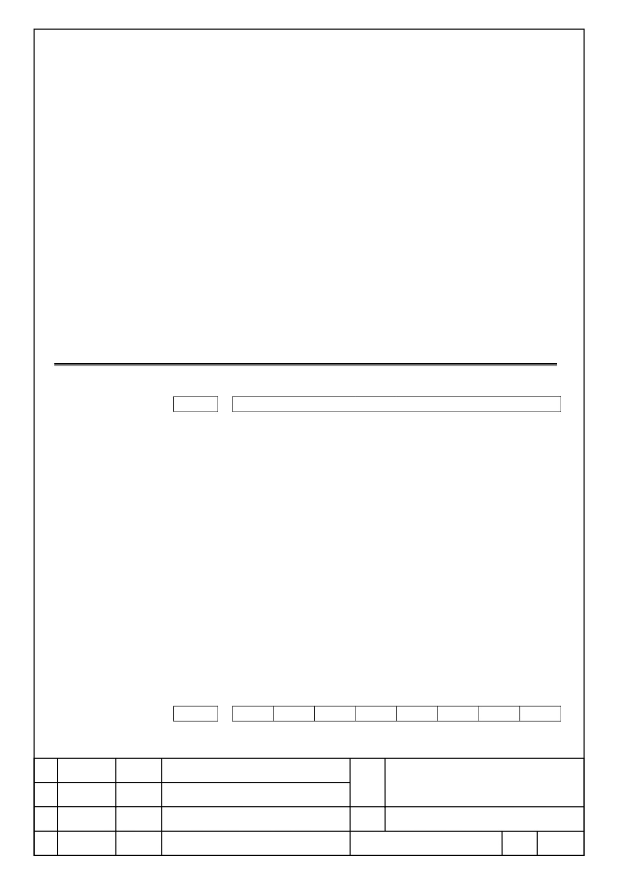
[TOOL] : Input a tool management information and tool database data.
[MAG] : Input a data of magazine management table.
[STATUS] : Input a name data of tool life information.
[CSTM] : Input a name data of customize data
To display the following 3 items, an option of tool management function
expansion is required.
[DSPCT] : Input screen customize data.
[P-NAME] : Input a name data of spindle/wait position.
[POINT] : Input a position of decimal point of customize data.
(4) After pressing a soft key of tool management data that you want to
input, check message is disaplayed. Press [ EXEC ] to input tool
management data they are input to memory card.
8.3.
Parameters
14845
TLTAB
Set the display position of each tab of tool management data,
magazine information, tool offset, and tool information.
1digit
Tool Management Data Tab
10 place
Magazine Data Tab
100 place
Tool Offset Tab
1000 place
Tool Data Tab
Set 1~4 to each value to set a displaying order of a tab.
Tab is no displayed when 0 is set. When 0 is set to all, it is displayed
by default sorting.
Default sorting display is as follows.
1st
Tool Management Data Tab
2nd
Magazine Data Tab
3rd
Tool Offset Tab
4th
Tool Data Tab
Please input the figure of four digits to this parameter. And the
figure of each digit must not overlap.
#7
#6
#5
#4
#3
#2
#1
#0
14705
#5
#4
Softkey [T-OFS]
FANUC MANUAL GUIDE i
Name
(Series16i/18i/21i-MB/TB)
OPERATOR’S MANUAL
Draw.
B-63874EN/05-1
Ed.
Date
Design
Description
Page
24/100
FANUC LTD.

#4
0 : Display.
1 : Undisplay.
Softkey [TOOL]
#5
0 : Undisplay.
1 : Display.
FANUC MANUAL GUIDE i
Name
(Series16i/18i/21i-MB/TB)
OPERATOR’S MANUAL
Draw.
B-63874EN/05-1
Ed.
Date
Design
Description
Page
25/100
FANUC LTD.