FANUC MANUAL GUIDE i. OPERATOR’S MANUAL - page 10
13.TOOL DATA BASE FUNCTION OPERATION
B-63874EN/05
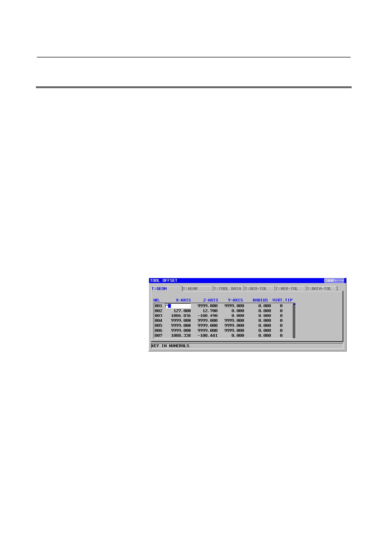
13.1 SETTING OF TOOL OFFSET DATA
For a compound machine, the following data items are displayed for
the T mode:
(1) T : GEOMETRY OFFSET
(2) T : WEAR OFFSET
(3) T : TOOL DATA
(4) T : GEOMETORY TOOL TYPE OFFSET
(5) T : GEOMETORY WEAR TYPE OFFSET
(6) T : GEOMETORY DATA TYPE OFFSET
The following data items are displayed for the M mode:
(7) M : TOOL OFFSET (TOOL LENGTH COMP. / CUTTER
COMPENSATION)
(8) M : TOOL DATA
(9) M : TOOL TYPE OFFSET
(TOOL LENGTH COMP.
/
CUTTER COMPENSATION)
(10) M : TOOL TYPE DATA
Each mode can be selected with [M←→T] soft key.
For lathes, data items (1) to (6) are displayed. For machining centers,
data items (7) to (10) are displayed.
The data to be set and displayed in (1), (2) and (7) is common to the
corresponding data in CNC. For details, refer to the operator’s manual
of the CNC.
And for lathes, inputting tip radius value of milling tools in “radius” is
necessary. If not, sometimes alarm is given.
For data items
(4),
(5) and
(9), which are related to the tool
management function, see the description of
“Tool Management
Function” in Appendix.
For data items (3), (6), (8) and (10), which is about tool form data, see
next section.
- 252 -
B-63874EN/05
OPERATION
13.TOOL DATA BASE FUNCTION
13.2 SETTING OF TOOL DATA
By selecting “tool data” tab in tool offset window, “tool data” setting
window is displayed. Tool data is the data that is necessary for
executing animation or cycle, and their items are tool radius, kind of
tool, name, setting and tool form data. Of all items, tool radius is
inputted into radius (for lathes) or cutter radius compensation (for
milling) in tool offset table. The rest is inputted in “TOOL DATA”
tab.
These data are reserved in SRAM, so once set, they aren’t deleted
though the power supply is cut. But more than 300 tools can’t be
inputted.
Besides, by parameter No.14850#0, you can decide whether “tool
data” tab is displayed or not.
13.2.1 Setting of Tool Type
By placing cursor on an item for selecting kind of tool, the following
soft keys appear. When appropriate soft key is pushed, a type of tool
is selected and its icon is displayed. Also tool name is displayed on the
right of the icon.
Soft keys for selecting kind of tool for lathes or T mode of combined
machine
GENERL
THREAD
GROOVE
BUTTON
STRAIT
CHCURS
INIT
NO.SRH
CLOSE
DRILL
CHAMFR
F END
B END
TAP
REAMER
BORING
F MILL
CLOSE
Soft keys for selecting kind of tool for machining centers or M mode
of combined machine
DRILL
CHAMFR
F END
B END
TAP
CHCURS
INIT
NO.SRH
CLOSE
REAMER
BORING
F MILL
CLOSE
- 253 -
13.TOOL DATA BASE FUNCTION OPERATION
B-63874EN/05
13.2.2
Editing of Tool Name
To edit tool name, place cursor on tool name, change mode into
character, input alphabets or numerals, and push INPUT.
This function is useful to distinguish similar tools.
13.2.3
Setting of Tool Set
When a cursor is placed on tool setting number, a guidance window is
automatically displayed in the right of the screen. By inputting tool
setting number and pushing INPUT, tool setting can be set.
13.2.4
Entering of Tool Data
By placing cursor on items of tool data, guidance window is
automatically displayed. By inputting tool data value and pushing
INPUT, tool data can be set. Then three-whole and one-decimal
number can be inputted when unit is [deg.]. When [inch] or [mm],
eight-figure number can be inputted. But numbers that is inputted to 7
decimal places are rounded off to 6 decimal places.
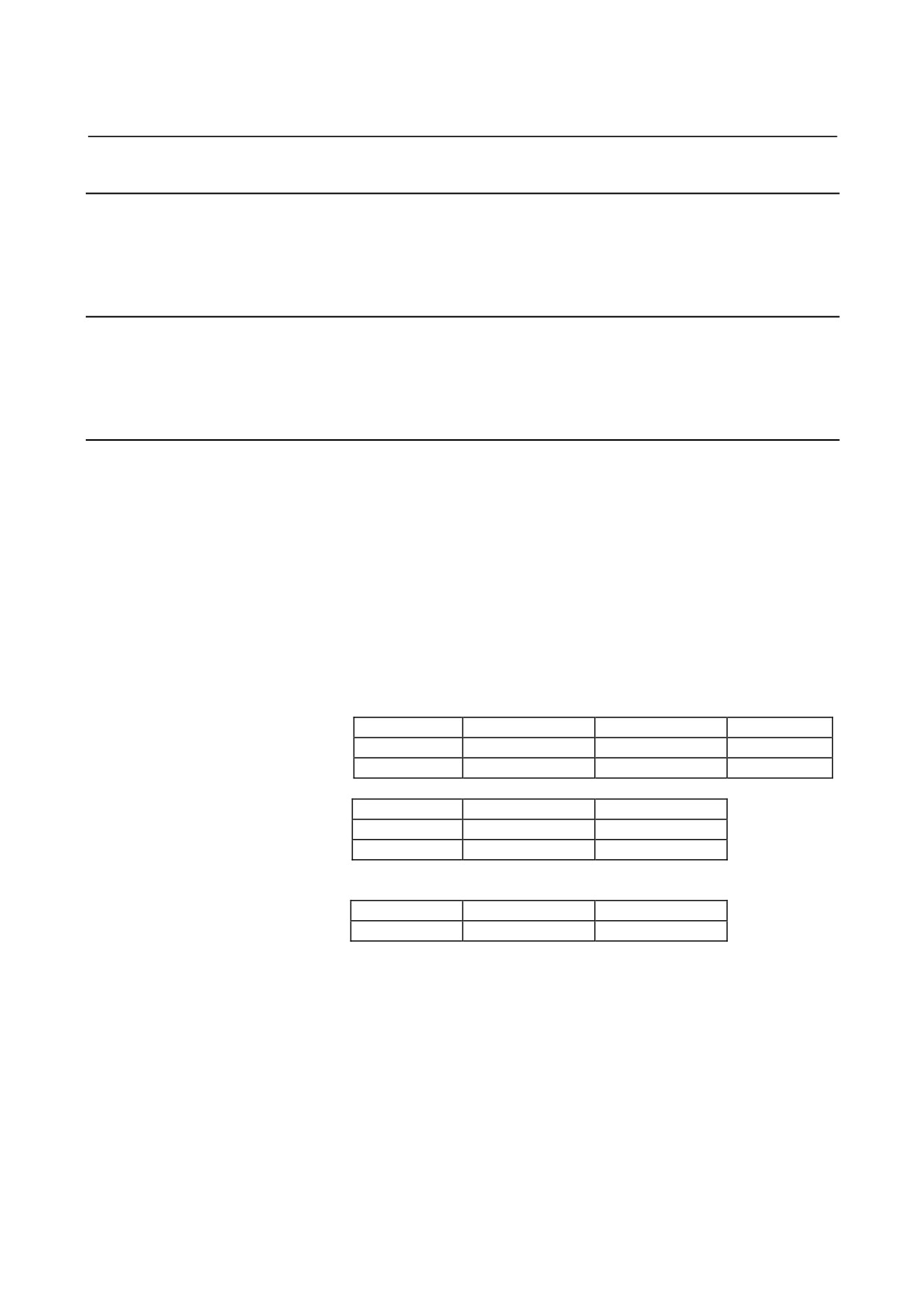
The names of item and the numbers of item depend on kind of tool.
See below about the detail. In this table, tools that don’t have to set
tool data are omitted.
Tool data isn’t necessary to execute milling cycle. So milling cycle
can be executed though tool data isn’t set.
Tool form data for turning
KIND OF TOOL
GENERAL
THREAD
GROOVE
Data1
Cutting edge angle
Nose angle
Tip width
Data2
Nose angle
Tip length (*)
KIND OF TOOL
BUTTON
STRAIGHT
Data1
Tip length (*)
Cutting edge angle
Data2
Nose angle
Tool form data for milling
KIND OF TOOL
DRILL
CHAMFER
Data
Nose angle (*)
Cutter diameter (*)
(*) : Cycle can be executed if not set
- 254 -
B-63874EN/05
OPERATION
13.TOOL DATA BASE FUNCTION
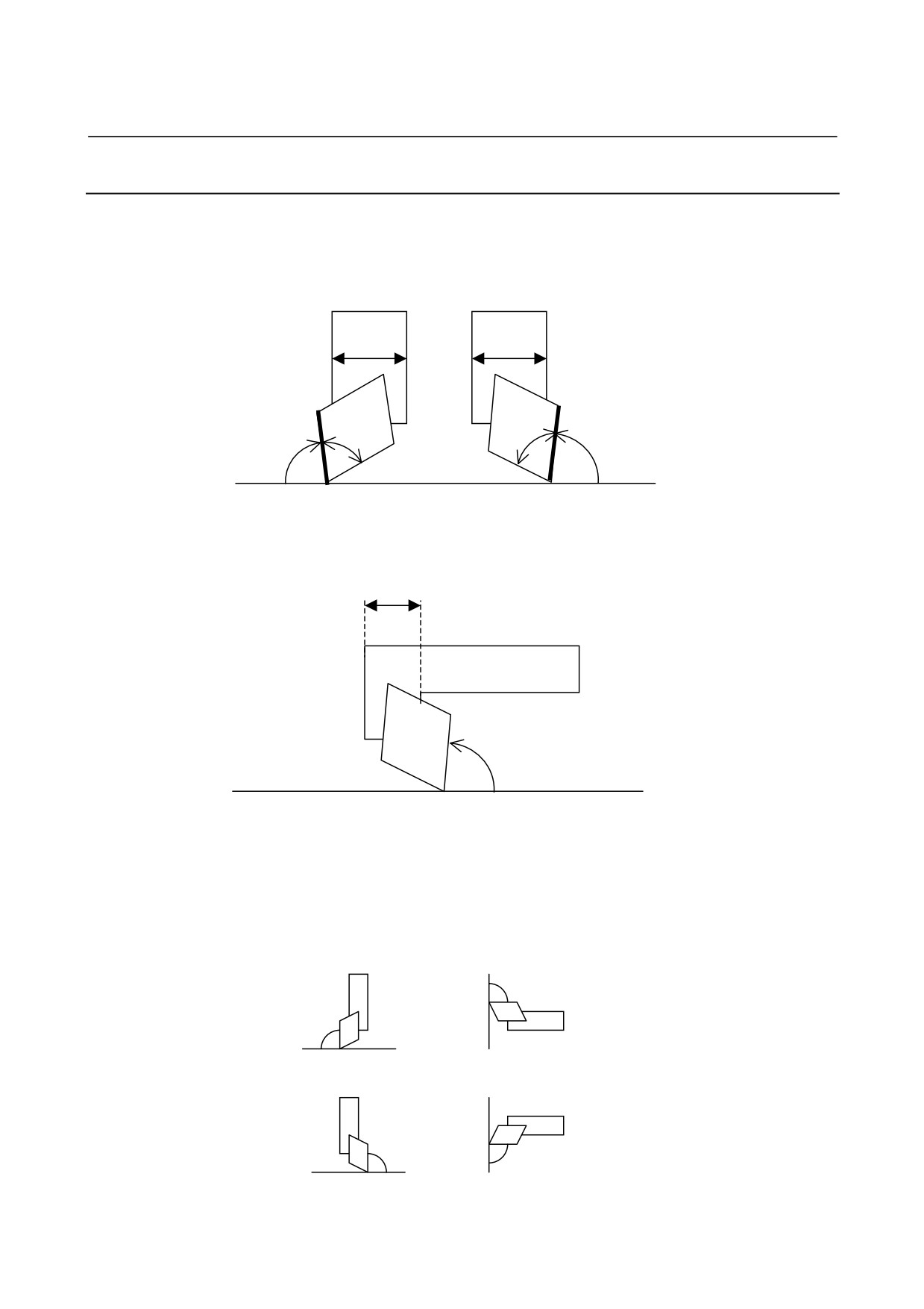
13.2.5 Cutting Edge angle of Tool Data Base Function
An angle that is made by a line parallel with holder width and cutting
edge is defined as a cutting edge angle.
Holder
Holder
Width
Width
T
T
An
An
Aa
Aa(Cutting Edge angle)
La (parallel with holder width)
1. Draw a straight line that is parallel with holder width
2. An angle that is made by a straight line La and a straight line T is
defined as a cutting edge angle
Holder Width
Aa(Cutting edge angle)
La(parallel with holder width)
3. In case of L form holder, the width of a part that is installed tip is
defined as holder width.
Actually MGi defines cutting edge angle from tool setting.
Show following concrete examples.
(set 1)
(set 2)
(set 5)
(set 6)
- 255 -

13.TOOL DATA BASE FUNCTION OPERATION
B-63874EN/05
(set 9)
(set 10)
(set 13)
(set 14)
13.2.6 Initializing of Tool Data
Tool data can be initialized by [INIT] soft key. When [INIT] is pushed,
a message for confirming initialization is displayed. By pressing
[YES], initialization is performed.
But items to be initialized are only items placed in tool data tab and
[INIT] has no connection with offset value.
- 256 -
B-63874EN/05
OPERATION
13.TOOL DATA BASE FUNCTION
13.3
SELECTING TOOL DATA AT PROGRAM ENTERING
To select dada number that is set in “TOOL DATA” tab, T code or D
code is used to work machines.
For lathes, T code is used to specify numbers of three types, tool
number, geometry tool offset number and wear tool offset number. In
these numbers, the geometry offset number will be used for actual
machine operations. There are some ways to specify geometry tool
offset, for example setting parameter No.5002#1. But in all case, the
geometry offset number will be used. With tool management function,
D code is used to select offset number. But in this case, the geometry
tool offset number will be used too.
For machining centers, the number of the cutter compensation that is
specified by D code will be used for actual machine operation.
For compound machines, when T mode, the way to appoint tool data
number is the same as lathes. So the same number of geometry tool
offset and runs machine.
When M mode, the way to appoint tool data number is the same as
machining centers. So the number of cutter compensation for actual
machine operation.
In animated simulation, when tool data number is selected by T code
or D code, a tool is drawn.
NOTE
There are 2 ways to draw tools. One is the way to
select tool data number above. The other is the
way to use G code. Place T (or D) code and G
code 2 blocks apart when G code follows T (or D
code). If T (or D) code and G code aren’t placed 2
blocks apart, order of G code sometimes doesn’t
work correctly.
The relation between the specified tool kind and machining cycle will
be checked. For example, if you try to use chamfer tool in drill cycle,
some corresponding alarm will occur. But when kind of tool isn’t
inputted, this checking will not done.
- 257 -
13.TOOL DATA BASE FUNCTION OPERATION
B-63874EN/05
13.4
SETTING OF TOOL GRAPHIC DATA
Several items are needed to execute machine simulation in addition to
items that explained up to here. These items are called Graphic Data.
Graphic Data is showed below.
13.4.1
Tool Graphic Data
Tool graphic data are defined by parameters, from No.27350 to
No.27383. When these parameters aren’t defined, appropriate value
will be inserted automatically. For details, refer to the description of
“Parameter” in APPENDIX.
Tool graphic data for turning tools
Kind of tool
General
Threading
Grooving
Data 1
Tip position
Tip position
Tip position
Data 2
Tip length
Tip width
Holder length
Data 3
Holder length
Holder length
Holder width
Data 4
Holder width
Holder width
Data 5
Holder length 2
Data 6
Holder width 2
Kind of tool
Button turning
Straight
Data 1
Tip position
Tip position
Data 2
Holder length
Tip length
Data 3
Holder width
Holder length
Data 4
Holder width
Data 5
Holder length2
Data 6
Holder width 2
Tool graphic data for milling tools
Kind of tool
Drill
Chamfer
Flat endmill
Ball endmill
Data 1
Tip length
Tip length
Tip length
Tip length
Data 2
Cutter length
Data 3
Shank length
Data 4
Shank diameter
Kind of tool
Tap
Reamer
Boring
Face mill
Data 1
Tip length
Tip length
Tip length
Tip length
- 258 -

B-63874EN/05
OPERATION
13.TOOL DATA BASE FUNCTION
13.5 ACCESSING TOOL DATA BASE FUNCTION
Accessing tool data base function is the function that tool data
registered in Manual Guide i are read or written from custom macro.
So, it is possible that tool data are accessed from a program. And
restoring the initial or copying tool data can be available.
13.5.1
Basic Specifications
The following data can be read and written.
1. Kind of tool
2. Setting
3. Tool data 1 ( ex. cutting edge angle )
4. Tool data 2 ( ex. nose angle )
NOTE
1 Tool name can’t be read and written.
2 The option of custom macro B is necessary to use
this function.
3 Only from custom macro or execution macro, tool
data can be read and written.
4 To enable this function, bit 6 of parameter No.
14852 must be set to 1.
In addition to reading and writing, the following functions are
available.
1.
Copying tool data
All tool data, including tool name, can be copied if source offset
number and destination offset number are designated.
2.
Initialization of tool data
Tool data per tool or all tool data can be restored the initial.
- 259 -
13.TOOL DATA BASE FUNCTION OPERATION
B-63874EN/05
13.5.2
System Variables
Tool data can be inputted or outputted from custom macro through
#5750 - #5756 system variables. Input adequate value to the system
variables when you want to access to tool data.
And when Manual Guide i find that adequate value have been set to it,
tool data is outputted or inputted.
The following system variables whose numbers are used for the
purpose of accessing tool data.
#5750 : The variable that is used to decide the working of
accessing tool data base function. Tool data will be
inputted or outputted from system variables when
Manual Guide i have detected the value of #5750. The
meanings are following.
0 : Do nothing
1 : Read tool data
2 : Write tool data
3 : Copy tool data from source to destination
4 : Restore the init tool data of designated
offset number
5 : Restore the init of all tool data
#5751 : Result
The meanings are following.
0 : Idle
1 : Normal finish
2 : Registered tool data number exceeds maximum
3 : Designating the working is wrong
4 : Designating offset number is wrong
5 : Designating kind of tool is wrong
(only when writing)
6 : Designating setting is wrong (only when writing)
7 : Designating data 1 is wrong (only when writing)
8 : Designating data 2 is wrong (only when writing)
#5752 : Designating offset number to be read or written. And in
case of copying tool data, Designating offset number of
the destination.
If wrong value is inputted, 4 will be returned to result in
reading or writing.
- 260 -
B-63874EN/05
OPERATION
13.TOOL DATA BASE FUNCTION
#5753 : Gotten kind of tool in reading or designated kind of tool
in writing. And in case of copying tool data,
Designating offset number of the source.
If wrong value is inputted, 5 will be returned to result in
writing.
10 : General tool
11 : Threading tool
12 : Grooving tool
13 : Button turning tool
14 : Straight tool
20 : Drill tool
21 : Chamfering tool
22 : Flat end mill tool
23 : Ball end mill tool
24 : Tap tool
25 : Reamer tool
26 : Boring tool
27 : Face mill tool
#5754 : Gotten setting of tool in reading and designated setting of
tool in writing. If wrong value is inputted, 6 will be
returned to result in writing.
#5755 : Gotten data 1 in reading and designated data 1 in writing.
If wrong value is inputted, 7 will be returned to result in
writing.
#5756 : Gotten data 2 in reading and designated data 2 in writing.
If wrong value is inputted, 8 will be returned to result in
writing.
13.5.3 Reading
In reading tool data, set offset number of tool data that should be
gotten to #5752 and set 1 to #5750. Each data will be outputted to
#5753, #5754, #5755 and #5756.
13.5.4 Writing
In writing tool data, set offset number of tool data that should be
written to #5752. And set tool data to #5753, #5754, #5755 and #5756.
Finally, set 2 to #5750. Each data will be reserved to memory field of
Manual Guide i .
13.5.5 Copying
In copying, set offset number of destination to
#5752, set offset
number of source to #5753 and set 3 to #5750. Manual Guide i will
copy tool data of source to destination.
- 261 -
13.TOOL DATA BASE FUNCTION OPERATION
B-63874EN/05
13.5.6 Initialization
In initialization, set offset number of tool data that should be restored
to the init to #5752 and set 4 to #5750. This tool data of designated
offset number will be restored to the init.
13.5.7 Initialization of All Tool Data
In initialization of all tool data, set 5 to #5750. All tool data will be
restored to the init. But in case of multi path system, the data that will
be restored to the init are only the data of the path that custom macro
executes.
And in case of compound machines, the data that will be restored to
the init are only the data of the mode that custom macro executes
(milling mode or turning mode).
- 262 -
B-63874EN/05 OPERATION 14.EDITING OF FREE FIGURE AND FIXED FORM FIGURE OF SUBPROGRAM FORM
14
EDITING OF FREE FIGURE AND FIXED
FORM FIGURE OF SUBPROGRAM
FORM
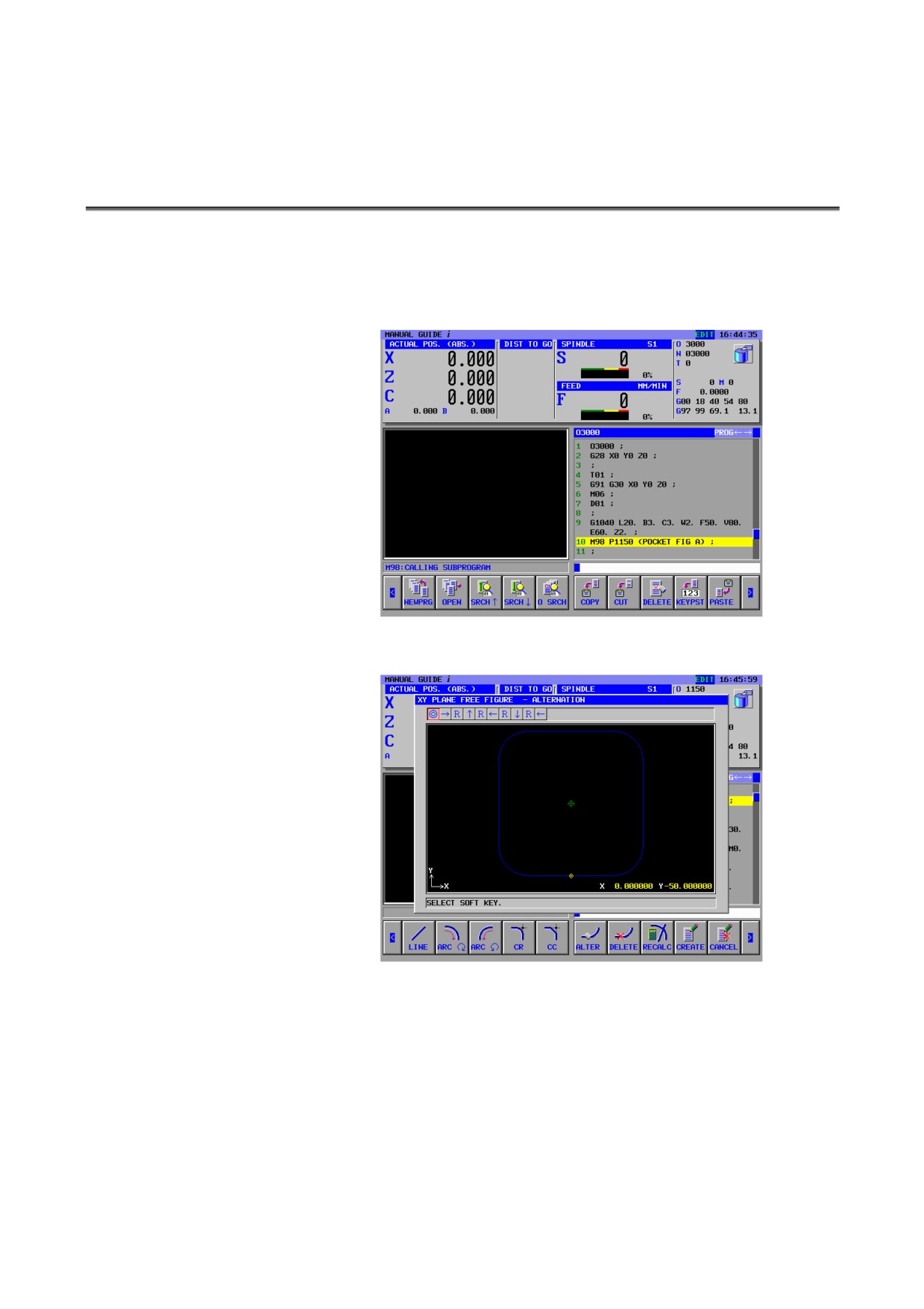
On the program editing screen, after moving the cursor on the sub
program call command (M98 P****) which is composed by the free
figure blocks or just one fixed form figure block, pressing the
[INPUT] key displays the window for editing the figures to edit
directly.
- 263 -
14.EDITING OF FREE FIGURE AND FIXED FORM FIGURE OF SUBPROGRAM FORM OPERATION B-63874EN/05
14.1 EDITING A FREE FORM FIGURE SUBPROGRAM
The operations are as follows.
(1) On the program editing screen, press the [INPUT] key or the
[ALTER] soft key after moving the cursor on the sub program
call command (M98 P****) which is composed by the free
figure blocks.
(2) The following window for editing the free figures included sub
program is displayed.
- 264 -
B-63874EN/05 OPERATION 14.EDITING OF FREE FIGURE AND FIXED FORM FIGURE OF SUBPROGRAM FORM
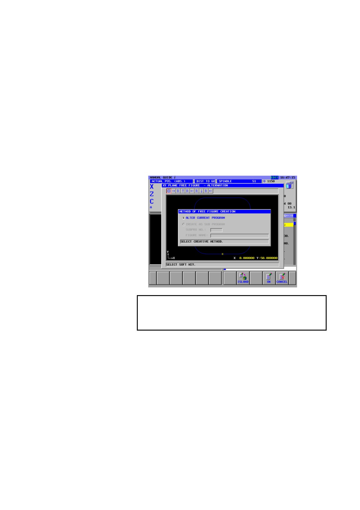
(3) On the window to finish editing the free figures, the operations
are as follows.
•
Pressing the [OK] soft key alters the existing blocks into the
editing figures in the machining program and returns to the
main program displaying screen.
But, at the case that the another free figures exist after the
editing figures, for example the island figures exist after the
pocket outer free figures, the editing window of the next
free figures is displayed.
•
At the case of editing the free figures for pocketing,
pressing the [ISLAND] soft key displays the window for
editing the free figures (“START POINT”) to make the new
island figures after altering the editing figures.
NOTE
On the editing sub program window, the free
figures cannot be output into the another sub
program.
- 265 -
14.EDITING OF FREE FIGURE AND FIXED FORM FIGURE OF SUBPROGRAM FORM OPERATION B-63874EN/05
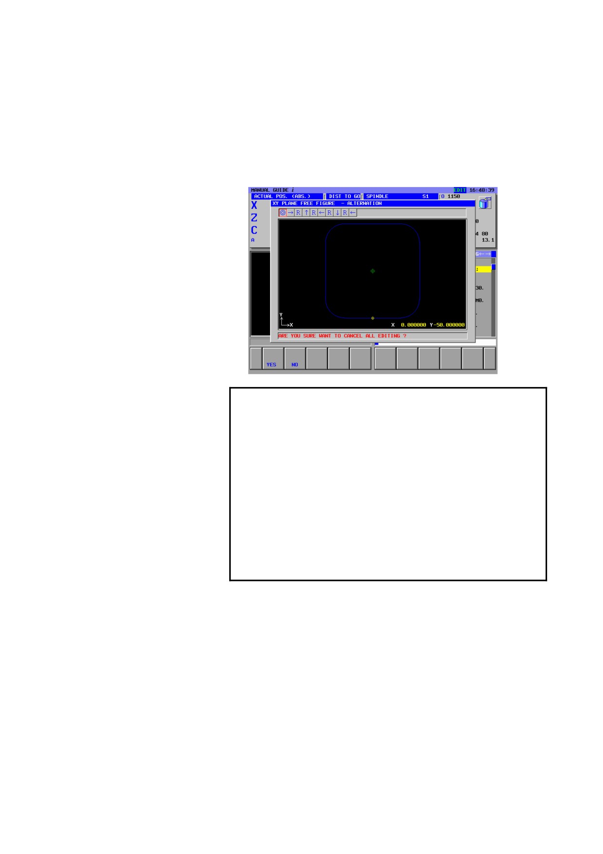
(4) On the window of editing the free figures, pressing the
[CANCEL] soft key displays a window for the confirmation to
interrupt editing. From this window, pressing the [YES] soft key
cancels the editing operations and returns to the main program
displaying screen.
NOTE
1 During editing the subprogram of free figure,
displaying free figure editing window, this editing
mode is canceled and the editing window is closed
by the following operations. The selected program
is kept to the edited subprogram.
• Mode is changed to other than EDIT mode when
foreground editing is done.
• Change to CNC screen.
• Power turned off.
2 In this case, the free figure editing window is
closed. The program that is then displayed in the
program display area is a subprogram.
- 266 -

B-63874EN/05 OPERATION 14.EDITING OF FREE FIGURE AND FIXED FORM FIGURE OF SUBPROGRAM FORM
14.2
WARNING MESSAGE
The following warning messages are displayed at the editing of the
subprogram.
•
“SUB PROGRAM IS NOT FOUND”
When the [INPUT] key or the [ALTER] soft key is pressed after
moving the cursor on the sub program call command, this
warning message is displayed at the case that the program
number specified by address ’P’ doesn’t exists.
•
“PROGRAM IS PROTECTED.”
When the [INPUT] key or the [ALTER] soft key is pressed after
moving the cursor on the sub program call command, this
warning message is displayed at the case that the program
number specified by address ’P’ is protected.
•
“PROGRAM IS NOT FREE FIGURE”
When the [INPUT] key or the [ALTER] soft key is pressed after
moving the cursor on the sub program call command, this
warning message is displayed at the case that the program
number specified by address ’P’ doesn’t include the free figure
blocks.
•
“PROGRAM IS SELECTED FOREGROUND
When the screen changes to the main program displaying screen
after the [OK] soft key or the [CANCEL] soft key is pressed at
background editing, this warning message is displayed at the case
that the main program is already selected at foreground.
14.3
EDITING A FIXED FORM FIGURE SUBPROGRAM
When bit 1 of parameter No. 14851 is set to 1, a fixed form figure in
subprogram form can be edited directly by placing the cursor on the
subprogram call command of the main program then pressing
[ALTER].
The procedure is as follows:
<1> Place the cursor on the block of a subprogram call command
(M98P****) of the main program, then press the [ALTER] soft
key or the [INPUT] key.
<2> The window for input of fixed form figure data on the
subprogram is displayed. Enter data, then press the [ALTER]
soft key.
<3> The modified data is output to the machining program, and the
fixed form figure data input window is closed. The main
program is then displayed again.
NOTE
When the cursor is placed on a subprogram call
command of the main program, fixed form figure
drawing is not performed on the graphic window.
- 267 -
15.SHORTCUT KEY OPERATIONS OPERATION
B-63874EN/05
15
SHORTCUT KEY OPERATIONS
On MANUAL GUIDE i, almost all the operations excepting
numerical data entering are done by soft-keys. However, if you are
well experienced in those operations, you can operate more quickly by
using other key instead of the assigned soft-key. This other key
operation is called shortcut key.
Pressing HELP key on the MDI panel displays the window in which
explanations of shortcut key are displayed. Into details, refer to II 16.
HELP SCREEN.
NOTE
If the small MDI key board is attached to the CNC,
shortcut key operations cannot be used.
- 268 -
B-63874EN/05
OPERATION
15.SHORTCUT KEY OPERATIONS
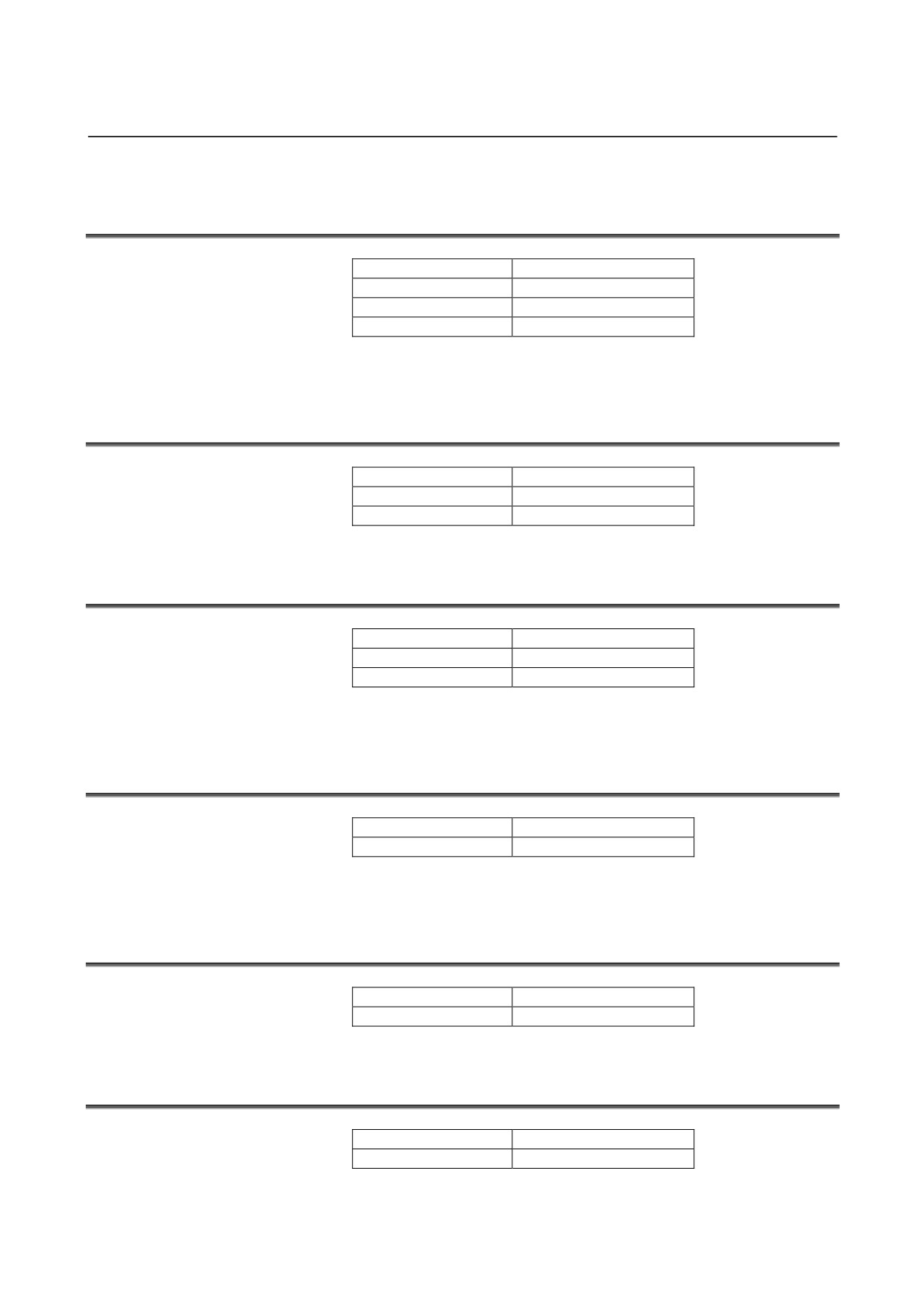
15.1 SHORTCUTS FOR VARIOUS CONFIRMATION
OPERATIONS
Soft key
Shortcut key
[ YES ]
[INPUT]
[ NO ]
[CAN]
15.2 SHORTCUTS FOR RANGE SELECTION
Soft key
Shortcut key
[SELECT]
[INPUT]
[CANCEL]
[CAN]
15.3 SHORTCUTS FOR COPY OPERATION
Soft key
Shortcut key
[COPY]
[INPUT]
[CANCEL]
[CAN]
15.4 SHORTCUTS FOR CUT OPERATION
Soft key
Shortcut key
[CUT]
[INPUT]
[CANCEL]
[CAN]
- 269 -
15.SHORTCUT KEY OPERATIONS OPERATION
B-63874EN/05
15.5 SHORTCUTS FOR THE BASE SCREEN SOFT KEYS
Soft key
Shortcut key
[<]
[-]+[INPUT]
[SF1]
[1]+[INPUT]
[SF2]
[2]+[INPUT]
[SF3]
[3]+[INPUT]
[SF4]
[4]+[INPUT]
[SF5]
[5]+[INPUT]
[SF6]
[6]+[INPUT]
[SF7]
[7]+[INPUT]
[SF8]
[8]+[INPUT]
[SF9]
[9]+[INPUT]
[SF10]
[0]+[INPUT]
[>]
[.]+[INPUT]
* By setting bit 1 of parameter No. 14703 to 1, a number for
shortcut operation can be displayed under each soft key.
15.6 SHORTCUT FOR STARTING THE CYCLE CHANGE
SCREEN
Soft key
Shortcut key
[ALTER]
[INPUT]
15.7 SHORTCUTS FOR THE MENU SELECTION SCREEN
Soft key
Shortcut key
[SELECT]
[INPUT] or numeral +[INPUT]
[CANCEL]
[CAN]
15.8 SHORTCUTS FOR THE REGULAR PROGRAM INSERTION
SCREEN
Soft key
Shortcut key
[INSERT]
[INPUT] or numeral +[INPUT]
[CLOSE]
[CAN]
- 270 -
B-63874EN/05
OPERATION
15.SHORTCUT KEY OPERATIONS
15.9 SHORTCUTS FOR THE M CODE INSERTION SCREEN
Soft key
Shortcut key
[INSERT]
[INPUT]
[CLOSE]
[CAN]
15.10 SHORTCUTS FOR THE PROGRAM LIST SCREEN
Soft key
Shortcut key
[OPEN]
[INPUT] or [9]
[CLOSE]
[CAN] or [0]
[DELETE]
[DELETE] or [3]
[EDTCOM]
[ALTER] or [4]
[NEW]
[1]
[COPY]
[2]
[SEARCH]
[5]
[M CARD]
[6]
[ALLDEL]
[7]
[SRTORD]
[8]
15.11 SHORTCUTS FOR THE PROGRAM CREATION SCREEN
Soft key
Shortcut key
[CREATE]
[INPUT]
[CANCEL]
[EOB]
15.12 SHORTCUTS FOR THE COMMENT EDITING SCREEN
Soft key
Shortcut key
[CREATE]
[INPUT]
[CANCEL]
[EOB]
15.13 SHORTCUTS FOR THE SEARCH SCREEN
Soft key
Shortcut key
[SEARCH]
[INPUT]
[CANCEL]
[EOB]
- 271 -
15.SHORTCUT KEY OPERATIONS OPERATION
B-63874EN/05
15.14 SHORTCUTS FOR THE CYCLE INPUT SCREEN
Soft key
Shortcut key
[INSERT]
[INSERT]
[ALTER]
[ALTER]
[CANCEL]
[EOB]
[SF1]
[1]
[SF2]
[2]
[SF3]
[3]
[SF4]
[4]
[SF5]
[5]
[SF6]
[6]
[SF7]
[7]
[SF8]
[8]
[SF9]
[9]
[SF0]
[0]
[>]
[.]+[INPUT]
15.15 SHORTCUT FOR THE WORKPIECE COORDINATE
SYSTEM SETTING SCREEN
Soft key
Shortcut key
[CLOSE]
[EOB]
15.16 SHORTCUT FOR THE TOOL OFFSET SETTING SCREEN
Soft key
Shortcut key
[CLOSE]
[EOB]
15.17 SHORTCUTS FOR THE REGULAR PROGRAM
REGISTRATION SCREEN
Soft key
Shortcut key
[CLOSE]
[INPUT]
[NEW]
[INSERT]
[DELETE]
[DELETE]
[ALTER]
[ALTER]
- 272 -
B-63874EN/05
OPERATION
15.SHORTCUT KEY OPERATIONS
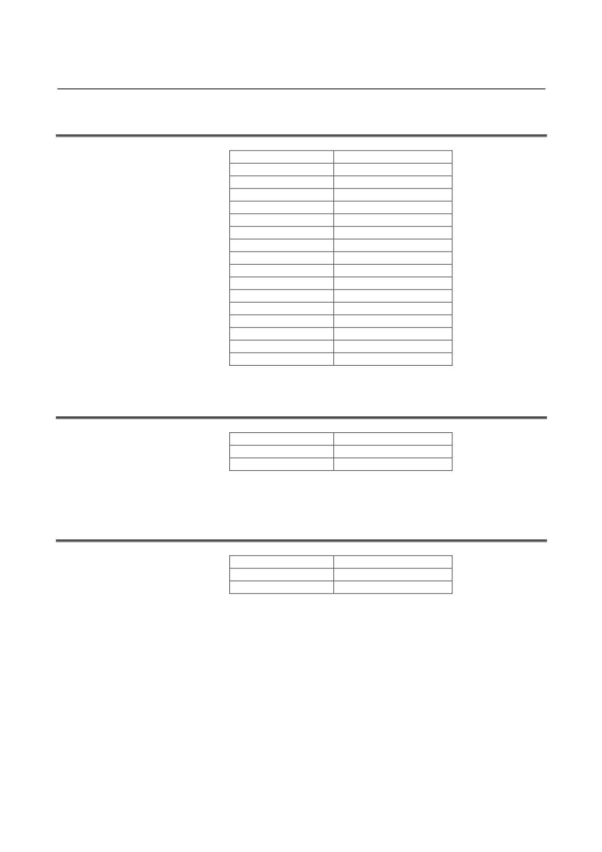
15.18 SHORTCUTS FOR THE CREATION SCREEN FOR
REGULAR PROGRAM REGISTRATION
Soft key
Shortcut key
[INSERT]
[INSERT]
[ADD]
[ALTER]
[CANCEL]
[EOB]
15.19 SHORTCUTS FOR THE ALTER SCREEN FOR REGULAR
PROGRAM REGISTRATION
Soft key
Shortcut key
[ALTER]
[ALTER]
[CANCEL]
[EOB]
15.20 SHORTCUTS FOR THE PRESET SCREEN
Soft key
Shortcut key
[ALTER]
[ALTER]
[CANCEL]
[EOB]
15.21 SHORTCUT FEEDRATE THE MEASUREMENT RESULT
SCREEN
Soft key
Shortcut key
[CLOSE]
[CAN]
15.22 SHORTCUT FOR THE MANUAL MEASUREMENT
SCREEN
Soft key
Shortcut key
[CLOSE]
[EOB]
15.23 SHORTCUT FOR VARIOUS SETTING SCREENS
Soft key
Shortcut key
[CLOSE]
[EOB]
- 273 -
15.SHORTCUT KEY OPERATIONS OPERATION
B-63874EN/05
15.24 SHORTCUTS FOR THE FREE FIGURE MAIN SCREEN
Soft key
Shortcut key
[CREATE]
[INPUT]
[CANCEL]
[CAN]
[DELETE]
[DELETE]
[ALTER]
[ALTER]
[<]
[-]
[SF1]
[1]
[SF2]
[2]
[SF3]
[3]
[SF4]
[4]
[SF5]
[5]
[SF6]
[6]
[SF7]
[7]
[SF8]
[8]
[SF9]
[9]
[SF10]
[0]
[>]
[.]
15.25 SHORTCUTS FOR THE FREE FIGURE INPUT SCREEN
Soft key
Shortcut key
[OK]
[INSERT]
[CANCEL]
[EOB]
15.26 SHORTCUTS FOR THE FREE FIGURE CREATION
SCREEN
Soft key
Shortcut key
[OK]
[INSERT]
[CANCEL]
[EOB]
- 274 -
B-63874EN/05
OPERATION
16.HELP SCREEN
16
HELP SCREEN
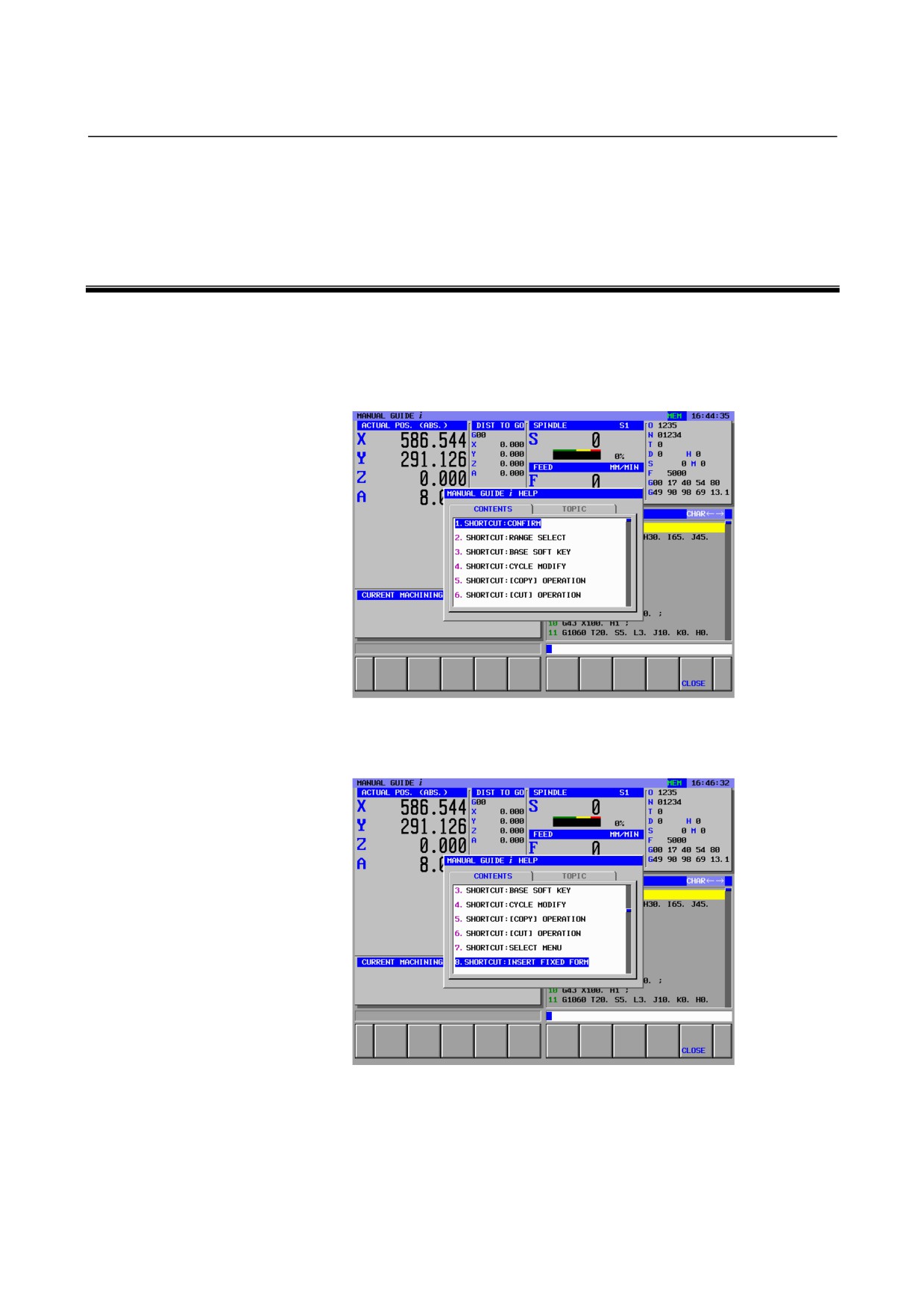
Pressing the [HELP] key on the MDI keyboard displays the HELP
window, in which explanations for shortcut key operation are
displayed.
In the window, “CONTENTS” and “TOPIC” tabs are displayed.
Moving the cursor by ↑ or ↓, place the cursor to the item of shortcut
key to display the explanation.
- 275 -
16.HELP SCREEN
OPERATION
B-63874EN/05
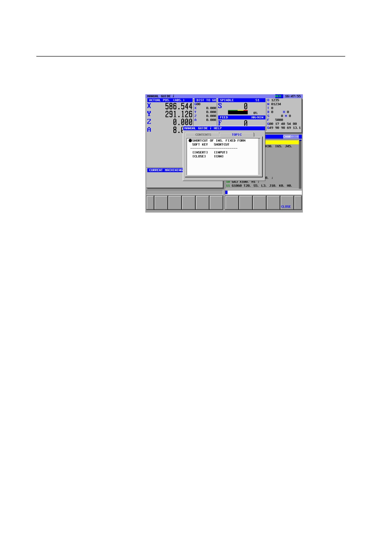
Pressing the cursor key
→ displays the tab
“TOPIC” tab and
explanation of the selected shortcut key.
Pressing the cursor key ← returns to “CONTENTS” tab.
Pressing [CLOSE] closes the HELP window.
- 276 -
B-63874EN/05
OPERATION
17.MEMORY CARD INPUT/OUTPUT FUNCTION
17
MEMORY CARD INPUT/OUTPUT
FUNCTION
- 277 -
17.MEMORY CARD INPUT/OUTPUT FUNCTION OPERATION
B-63874EN/05
17.1 MEMORY CARD INPUT/OUTPUT OF PART PROGRAM
17.1.1 Memory Card Input/Output Screen of Part Program
NEWPRG
O LIST
SRCH↑
SRCH↓
O SRCH
COPY
CUT
DELETE
KEYPST
PASTE
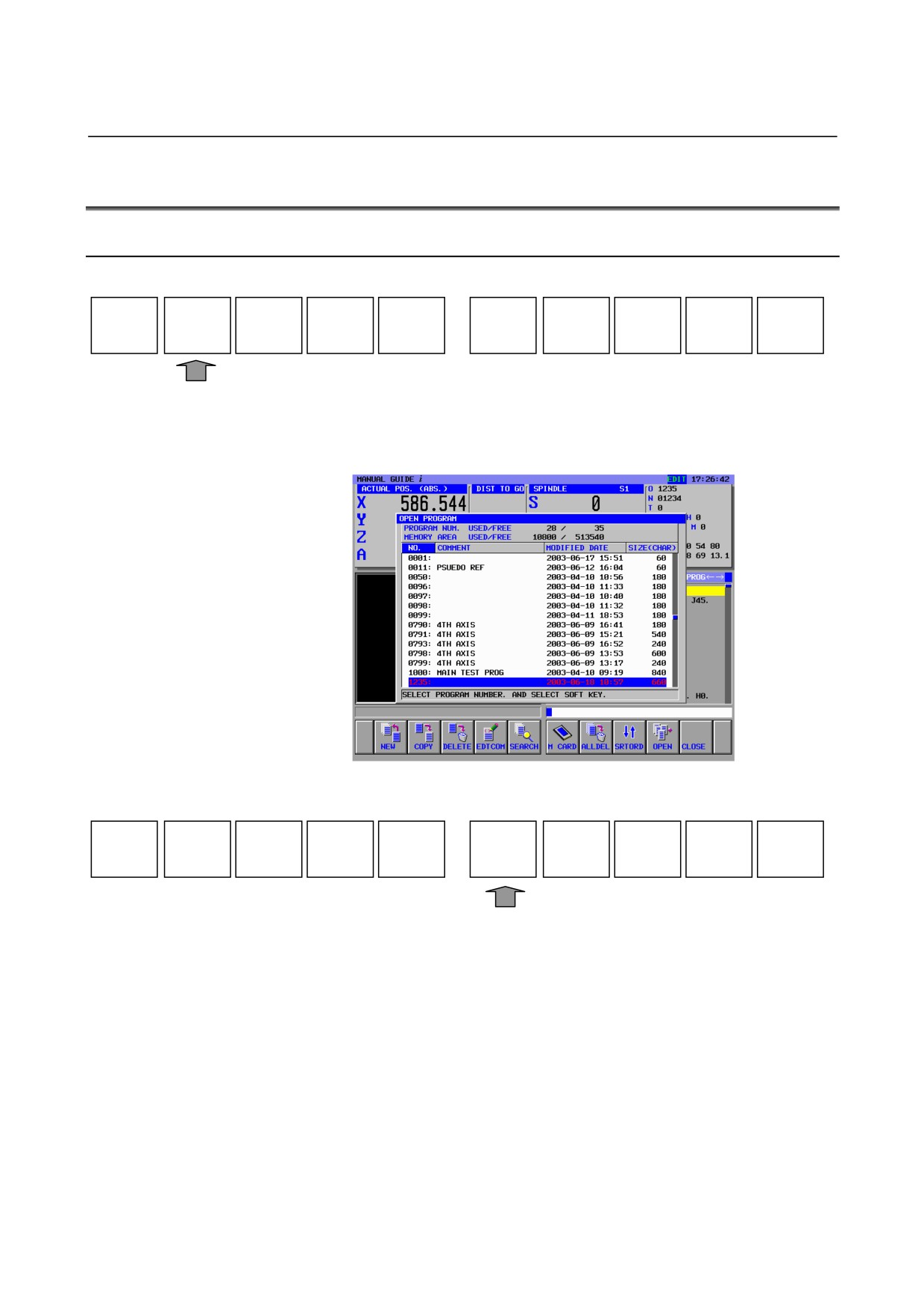
Select EDIT mode on the machine operator’s panel. Pressing [O
LIST] displays the program list window, programs registered in the
CNC.
Following soft-keys are displayed.
NEW
COPY
DELETE
EDTCOM
SEARCH
M CARD
ALL DEL
SRTORD
OPEN
CLOSE
- 278 -
B-63874EN/05
OPERATION
17.MEMORY CARD INPUT/OUTPUT FUNCTION
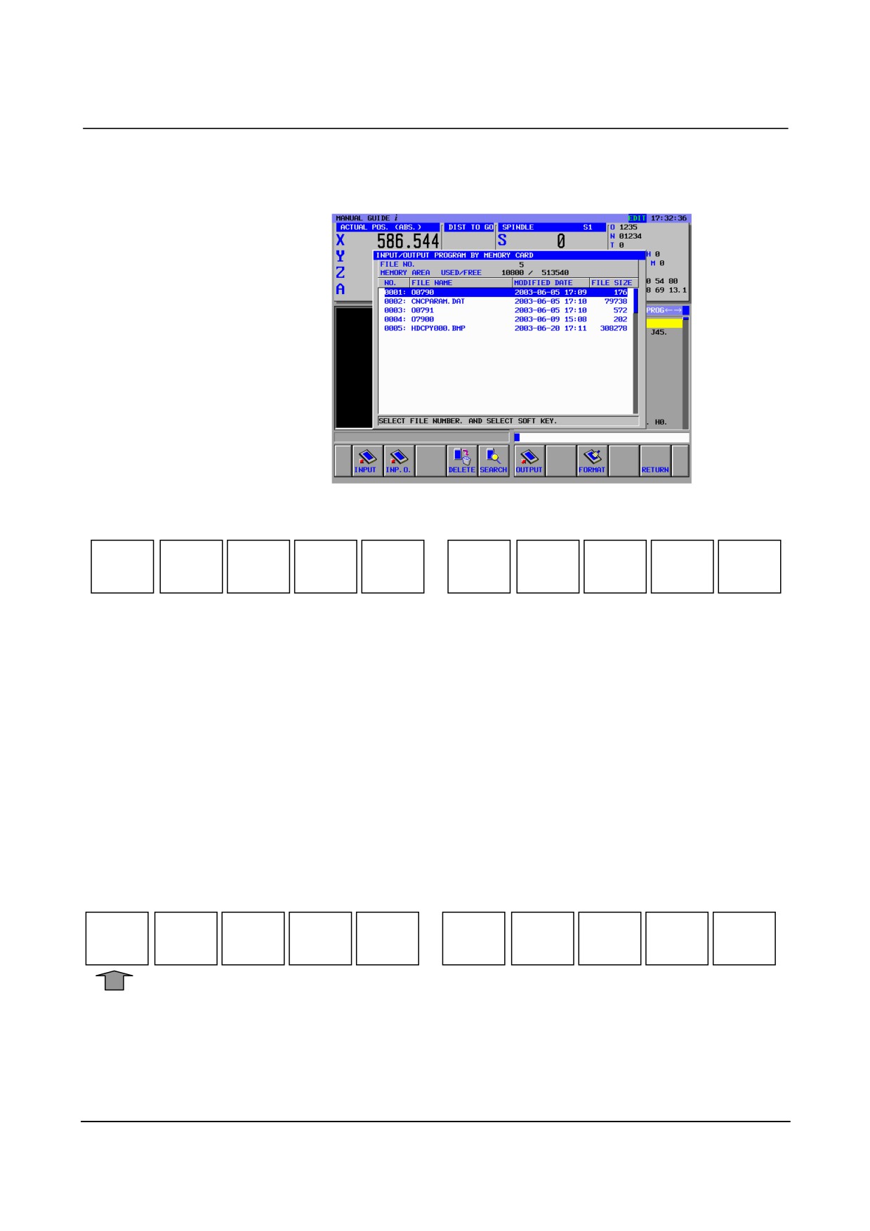
Pressing the [M CARD] soft key on the program list screen displays
the INPUT/OUTPUT PROGRAM BY MEMORY CARD]screen.
Following soft-keys are displayed.
INPUT
INP.O
DELETE
SEARCH
OUTPUT
FORMAT
RETURN
[INPUT]
: Inputs a program from the memory card.
[INP.O]
: Inputs a program from the memory card (by changing
the O number).
[DELETE]
: Deletes files on the memory card.
[SEARCH] : Searches for a file on the memory card.
[OUTPUT] : Displays the screen for output to the memory card.
[FORMAT] : Formats the memory card.
[RETURN] : Returns the screen display to the program list screen.
In order to delete a file in the memory card, place the cursor on the file
name in the above window and press [DELETE]. This soft key
displays a message for checking if selected file may be deleted.
Pressing [YES] deletes the file in the memory card. Pressing [NO]
cancels the deletion of all programs.
YES
NO
In case of initializing the memory card such as deleting all files in the
memory card, press [FORMAT]. This soft key displays a message for
checking if the memory card may be initialized. Pressing
[YES]
initializes the memory card and all files in the memory card are
deleted.. Pressing [NO] cancels the deletion of all programs.
17.1.2 Memory Card Output Operation for Part Program
- 279 -
17.MEMORY CARD INPUT/OUTPUT FUNCTION OPERATION
B-63874EN/05
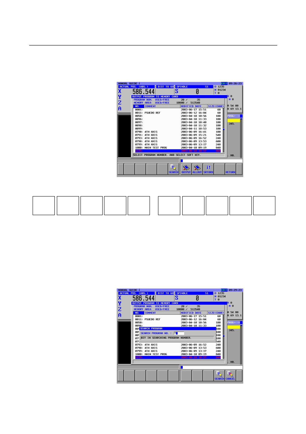
Pressing the
[OUTPUT] soft key on the INPUT/OUTPUT
PROGRAM BY MEMORY CARD screen displays the OUTPUT
PROGRAM TO MEMORY CARD screen.
The following soft-keys are displayed.
SEARCH
OUTPUT
ALLOUT
SRTORD
RETURN
[SEARCH] : Searches for a program.
[OUTPUT] : Output a selected program to the memory card.
[ALLOUT] : Output all programs to the memory card.
[SRTORD] : Switches the sort order for displaying a program list
between ascending order and descending order.
[RETURN] : Returns the screen display to the [INPUT/OUTPUT
PROGRAM BY MEMORY CARD] screen.
Pressing
[SEARCH] displays the following window of program
searching.
Enter the program number to be searched, then press [SEARCH].
- 280 -
B-63874EN/05
OPERATION
17.MEMORY CARD INPUT/OUTPUT FUNCTION
1.
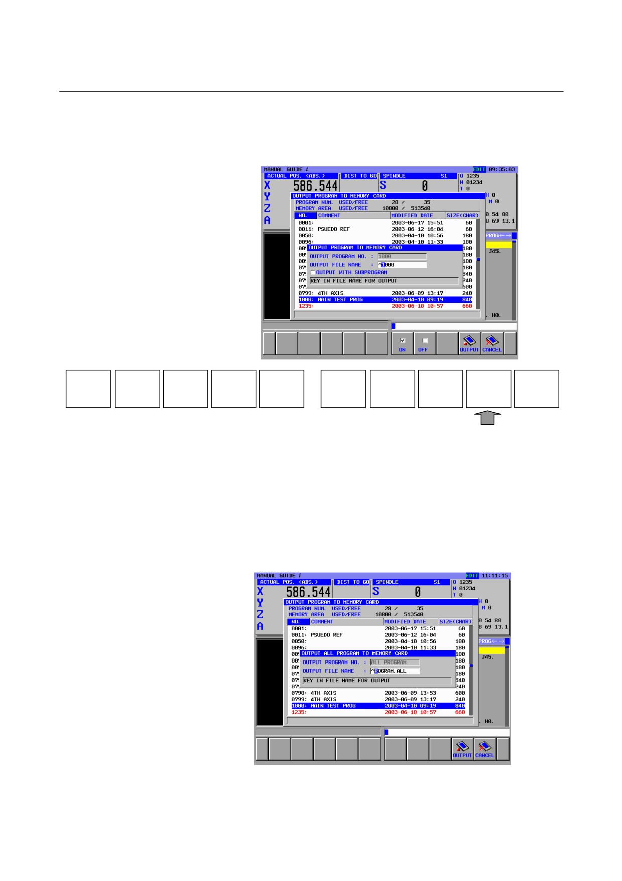
Output single part program
Select the part program to be outputted by placing the cursor on
it. Pressing
[OUTPUT] displays the following window for
entering outputting file name.
ON
OFF
OUTPUT
CANCEL
If the program number can be used as the outputted file name,
press [OUTPUT] without entering file name.
In case that the outputted file name should be changed, enter the
file name to OUTPUT FILE NAME and press [OUTPUT].
In order to output the selected program together with subprogram
called from the program, press
[ON] for OUTPUT WITH
SUBPROGRAM item. If not, press [OFF].
2. Output all part programs
Pressing [ALLOUT] displays the following window for entering
outputting file name.
If the file name “PROGRAM ALL” can be used as it is, press
[OUTPUT] without entering file name and all part programs stored
- 281 -