FANUC Series 16i/160i/160is-MODEL B, Series 18i/180i/180is-MODEL B, Series 21i/210i/210is-MODEL B. MAINTENANCE MANAUL - page 35
G. FSSB START-UP PROCEDURE/
MATERIALS
APPENDIX
B-63525EN/02
D
MDI input is abnormal (each time data is entered, the power needs to
G.7
be turned off).
ACTIONS FOR
First, disconnect the optical cable of the NC, then turn off then on the
TROUBLE
power. Next, check the items below.
ENCOUNTERED AT
(A) Check parameter No. 1902.
START-UP TIME
Action: hen parameter
No. 1902 = 00000000, set the following:
No. 1905 = 00000000
Nos. 1910 through 1919 = 0
Action: hen parameter
No. 1902 = 00000001 or 00000010, set the following:
No. 1905 = Appropriate value
Nos. 1910 through 1919 = Appropriate value
(B) When bit 1 of parameter No. 1815 = 1, check parameter Nos.
1910 through 1919 to see if 16 or 48 is set.
Action: If neither 16 nor 48 is set, set bit 1 of No. 1815 to 1.
(C) Check if communication is open (the green LED is on).
Action: If communication is not open, check the power supply
for the amplifier and optical cable connection.
D
The separate detector can be recognized, but feedback pulses from the
separate detector are abnormal.
(A) Check parameter No. 1902.
Action: The setting of parameter
No. 1902 = 00000000 is incorrect. When parameter
No. 1902 = 00000001, set the following:
No. 1905 = 01000000 or 10000000
Nos. 1910 through 1919 = Appropriate value
Nos. 1936 and 1937 = Appropriate value
Action: When parameter No. 1902 = 00000010, set connector
numbers for M0 and M1 in axis setting on the FSSB
screen.
D
In axis setting on the FSSB screen, connector numbers for M1 and M2
cannot be set.
Action: Check the FSSB screen to see if separate detector interface
unit IDs are read correctly. If pulse module IDs are not read
correctly, check the separate detector interface unit
connections.
D
The settings on the FSSB screen are canceled when the power is turned
off then back on.
Action: After setting desired values, press soft key [SETING] on the
amplifier setting screen and axis setting screen.
D
P/S alarm 5138 “AXIS SETTING NOT COMPLETE” is issued.
Action: Automatic setting on the FSSB screen is not terminated
normally. Make settings correctly on the FSSB amplifier
setting screen and axis setting screen, and press soft key
[SETING] on both screens. At this time, be sure to make
settings on the amplifier setting screen and the axis setting
screen in this order.
992
G. FSSB START-UP PROCEDURE/
B-63525EN/02
APPENDIX
MATERIALS
Action: When automatic setting on the FSSB screen is not
performed, set all of parameter Nos. 1902, 1905, 1910
through 1919, 1936, and 1937 to 0 before starting manual
setting.
D The invalid amplifier/motor combination alarm (466) is issued.
Action: Check if the maximum current value of the amplifier read on
the ID screen matches the setting of parameter No. 2165.
Recheck the amplifier/motor combination.
Action: Initialize the servo parameters of each axis.
D When the power is turned off then back on after modifying parameter
No. 1902, the system alarm (920) is issued.
Action: Disconnect the optical cable of the CNC, then turn off then
on the power.
Set all of parameter Nos. 1902, 1905, 1910 through 1919,
1936, and 1937 to 0, then turn off then on the power, then
make an FSSB setting all over again.
993
G. FSSB START-UP PROCEDURE/
MATERIALS
APPENDIX
B-63525EN/02
G.8
EXAMPLES OF
SETTINGS USING
OTHER
CONNECTIONS
G.8.1
Example 1: Learning
Control
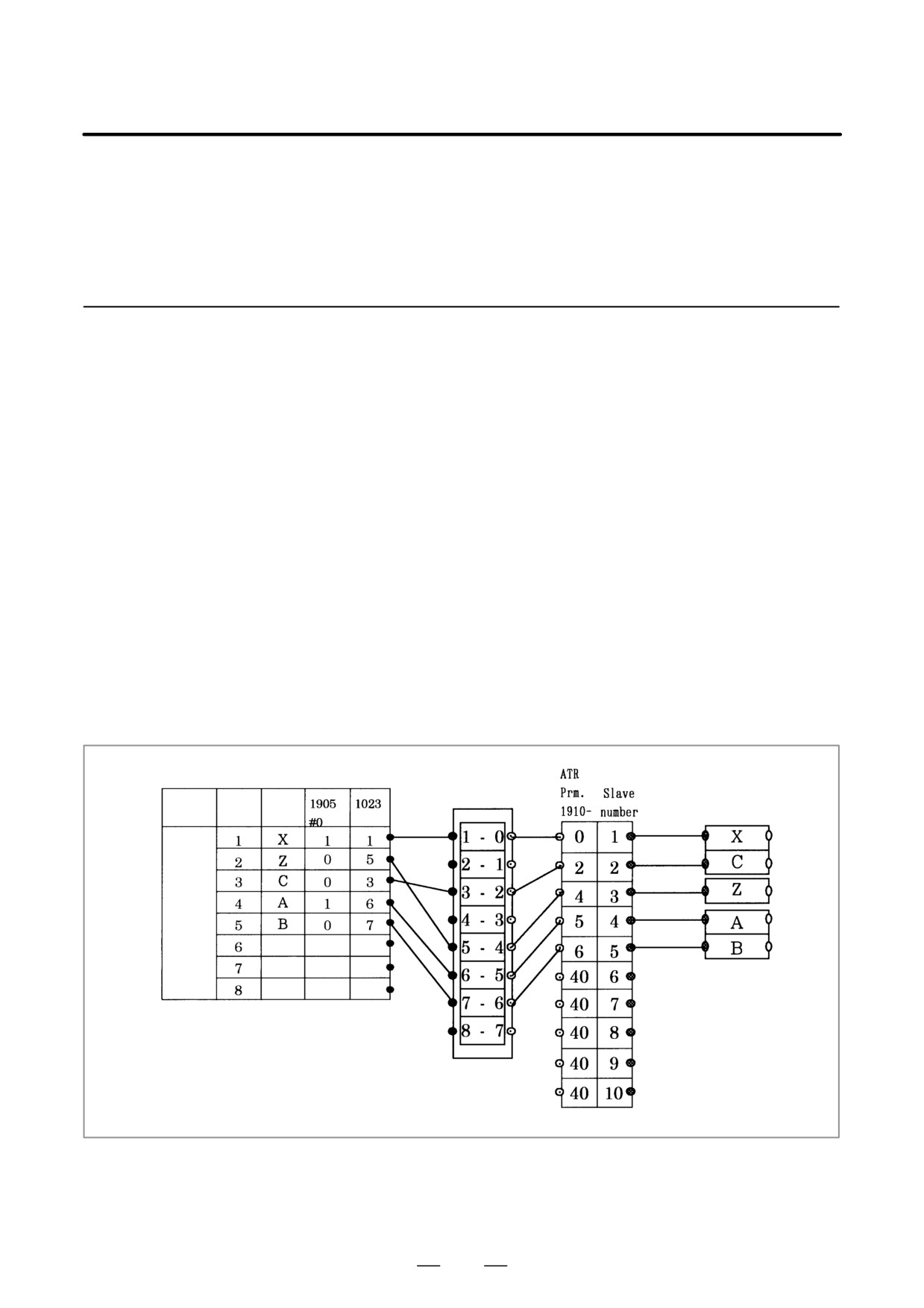
D Conceptual diagram of
When learning control is used, one NC controlled axis uses one DSP (two
FSSB parameter setting
axes of the servo axis card) exclusively.
for using learning
(1) Set bit 0 of parameter No. 1902 to 1 to disable automatic setting.
control
(2) Assign two axes of the axis card to each of learning control axes X and
C. (Parameter No. 1023 X = 1, C = 3)
(3) Assign the remaining controlled axes to the axis card (Parameter No.
1023 Z = 5, A = 6, B = 7)
(4) Set bit 0 of parameter No. 1905 to 1 for the A-axis, for which an even
number is set in parameter No. 1023.
(5) When using a 2-axis amplifier, one of the two axes must always be set
for the slow type. So, set bit 0 of parameter No. 1905 to 1.
(6) Set the attributes of parameter Nos. 1910 through 1914 to 0, 2, 4, 5,
and 6, and set the attributes of the remaining parameters to 40 (for
absence of a slave).
Axis card
Amplifi-
Axis Name
er/motor
Path 1
994
G. FSSB START-UP PROCEDURE/
B-63525EN/02
APPENDIX
MATERIALS
G.8.2
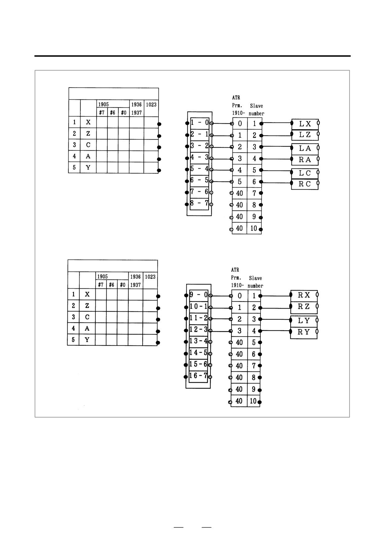
Example: FSSB setting for the following:
Example 2: When a
Hardware connection
2-Axis Amplifier is
Mother board - 2-axis amplifier (LX/LZ) - 2-axis amplifier
(LA/RA) - 2-axis amplifier (LC/RC)
Shared by Two Paths
Sub-board
-
2-axis amplifier
(RX/RZ)
-
2-axis amplifier
(LY/RY)
Controlled axis configuration
Mother board: LX, LZ, LC, LA, LY
Sub-board: RX, RZ, RC, RA, RY
Method of setting
When the servo system of another path is controlled as in this example,
automatic FSSB setting is not possible. Manual setting needs to be
used.
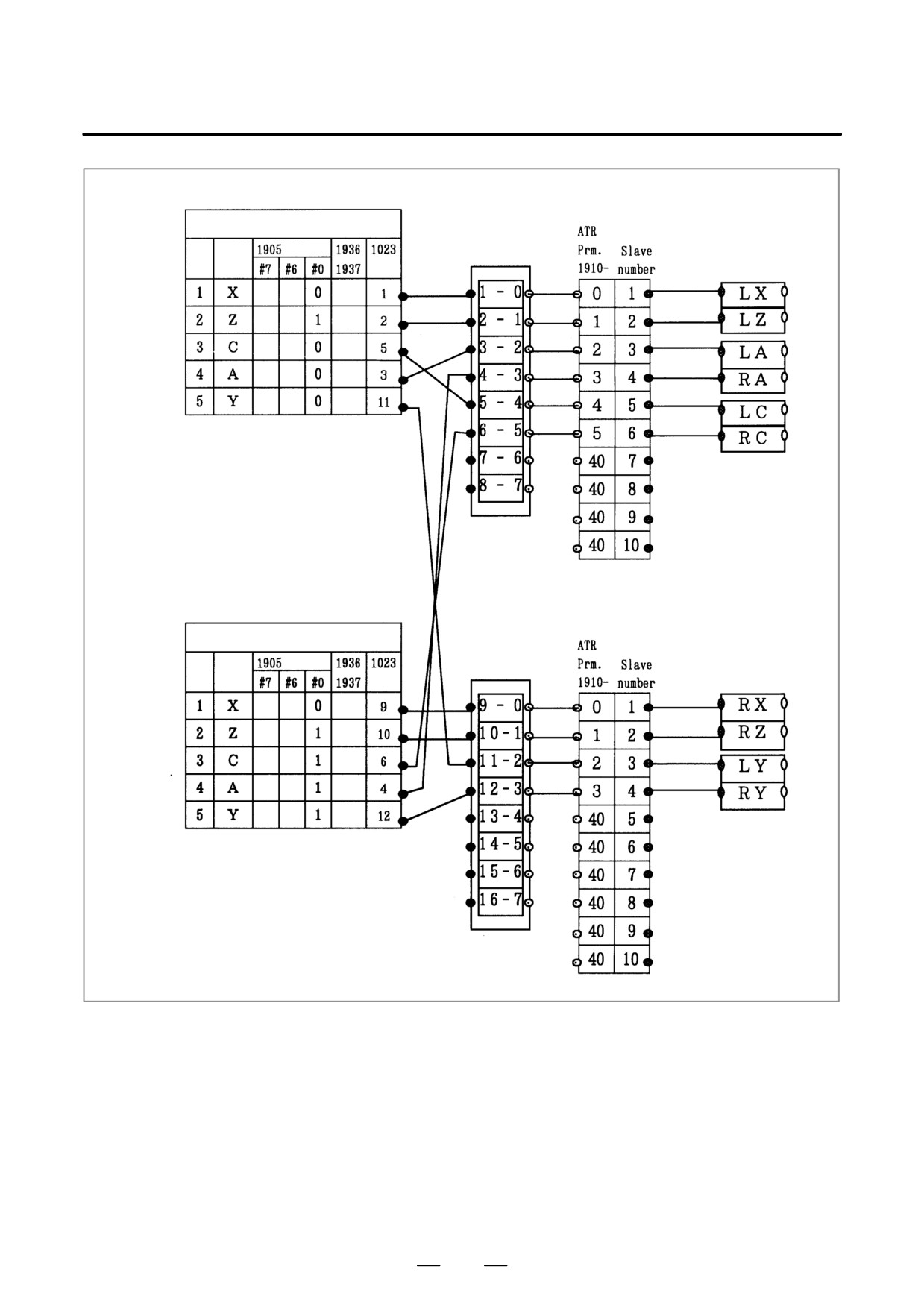
D FSSB setting procedure
When a motor connected to a path other than the local path is to be used
for controlling servo
in using a 2-axis amplifier, set the axis card number (DSP) of the
axes of another path in a
remote path in parameter No. 1023.
multi-path system
Procedure for setting
(1) Set bit 0 of parameter No. 1902 to 1 to use the manual setting mode.
(2) By hardware connection, the slave number of each motor is
determined. So, in parameter Nos. 1910 through 1919, set (slave
number - 1) and 40 (for absence of a slave).
995
G. FSSB START-UP PROCEDURE/
MATERIALS
APPENDIX
B-63525EN/02
Path 1
Axis Name
Axis card
Amplifi-
er/motor
Path 2
Axis Name
Axis card
Amplifi-
er/motor
(3) Set an axis card number (DSP number) in parameter No. 1023 to
connect an NC controlled axis with a motor.
(4) For an axis for which an even number is set in parameter No. 1023, set
bit 0 of parameter No. 1905 to 1.
With the settings above, a servo motor connected to another path can be
controlled.
When a separate detector interface unit is connected to use a separate
scale, bits 7 and 6 of parameter No. 1905, and parameter Nos. 1936 and
1937 need also be set.
996
G. FSSB START-UP PROCEDURE/
B-63525EN/02
APPENDIX
MATERIALS
Path 1
Axis Name
Axis card
Amplifi-
er/motor
Path 2
Axis Name
Axis card
Amplifi-
er/motor
997
G. FSSB START-UP PROCEDURE/
MATERIALS
APPENDIX
B-63525EN/02
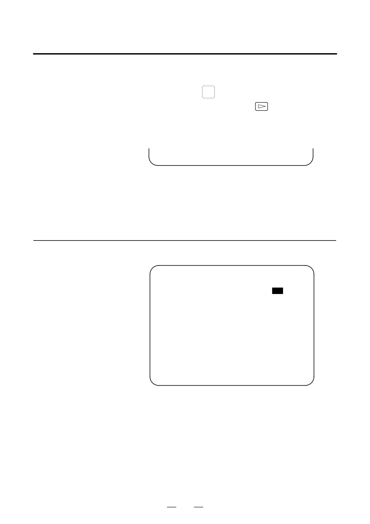
The FSSB setting screen displays FSSB-based amplifier and axis
G.9
information, and allows amplifier and axis information to be set.
FSSB DATA DISPLAY
SYSTEM
1
Press function key
2
Pressing the continuous menu key
several times displays
[FSSB].
3
Pressing soft key [FSSB] switches the screen display to the amplifier
setting screen (or the FSSB setting screen selected previously), and
displays the following soft keys:
[ AMP
][ AXIS
][ MAINT ][
][ (OPRT) ]
There are three types of FSSB setting screens: the amplifier setting screen,
axis setting screen, and amplifier maintenance screen.
Pressing soft key [AMP] switches the screen display to the amplifier
setting screen.
Pressing soft key [AXIS] switches the screen display to the axis setting
screen.Pressing soft key [MAINT] switches the screen display to the
amplifier maintenance screen.
G.9.1
The amplifier setting screen displays slave information divided into
amplifier information and separate detector interface unit information.
Amplifier Setting
Screen
(AMPLIFIER SETTING)
O1000 N00001
NO.
1
A1-L
α
SVM-HV
40AL
1
X
2
A1-M
α
SVM
12A
2
Y
3
A2-L
β
SVM
40A
3
Z
4
A3-L
α
SVM
20A
4
A
5
A3-M
α
SVM
40A
5
B
7
A4-L
α
SVU
240A
6
C
NO.
PCB ID
6
M1
A
0000 DETECTOR(8AXES)
8
M2
B
12AB
>_
MDI **** *** ***
13:11:56
[ AMP
][ AXIS
][ MAINT ][
][ (OPRT) ]
The amplifier setting screen displays the items below.
D NO.: Slave number
The serial numbers for to up to ten slaves (up to eight amplifiers and
up to two pulse modules) connected via the FSSB are displayed
sequentially. A younger number is assigned to a slave closer to the
CNC.
D AMP: Amplifier type
Amplifier type information starts with the character A, which stands
for “amplifier.” The character A is followed by the ordinal number of
an amplifier counted from the amplifier closest to the CNC, then is
followed by a letter indicating which axis of the amplifier is used (L
for the first axis, and M for the second axis).
998

G. FSSB START-UP PROCEDURE/
B-63525EN/02
APPENDIX
MATERIALS
D
AXIS NO: Controlled axis number
The controlled axis numbers set in parameter Nos. 1920 through 1929
are displayed.
When a value outside the range 1 to the maximum number of
controlled axes is set, 0 is displayed.
D
NAME: Controlled axis name
The axis name set in the parameter No. 1020 corresponding to a
controlled axis number is displayed. When the controlled axis number
is 0, - is displayed.
D
As amplifier information, the following information items are
displayed:
S UNIT: Type of servo amplifier unit
S SERIES: Servo amplifier series
S CURRENT: Maximum current value
D
As separate detector interface unit information, the information items
below are displayed.
S EXTRA
The character M, which stands for “separate detector interface
unit,” is followed by the ordinal number of a separate detector
interface unit counted from the separate detector interface unit
closest to the CNC.
S TYPE
The type of a separate detector interface unit is displayed by a letter.
S PCB ID
The ID of a separate detector interface unit is displayed using four
digits in hexadecimal. For a separate detector module (8 axes),
DETECTOR (8AXES) is displayed after the separate detector
interface unit ID. For a separate detector module
(4 axes),
DETECTOR (4AXES) is displayed after the separate detector
interface unit ID.
G.9.2
The axis setting screen displays axis information.
Axis Setting Screen
(AXIS SETTING)
O1000 N00001
M1 M2
Cs
1
X A1-L
0
0
0
0
1
2
Y A1-M
1
0
1
0
0
3
Z A2-L
0
0
0
1
0
4
A A3-L
0
0
0
0
2
5
B A3-M
0
0
0
0
0
6
C A4-L
0
0
0
0
0
>_
MDI **** *** ***
13:11:56
[ AMP
][ AXIS
][ MAINT ][
][ (OPRT) ]
999
G.
FSSB START-UP PROCEDURE/
MATERIALS
APPENDIX
B-63525EN/02
The axis setting screen displays the items below.
D
AXIS NO: Controlled axis number
The NC controlled axis numbers are displayed sequentially.
D
NAME: Controlled axis name
D
AMP:
Type of amplifier connected to each axis
D
M1:
Connector number for separate detector interface unit 1
The connector number for separate detector interface unit 1 set in
parameter No. 1931 is displayed.
D
M2:
Connector number for separate detector interface unit 2
The connector number for separate detector interface unit 2 set in
parameter No. 1932 is displayed.
D
1DSP
The value set in bit 0 (1DSP) of parameter No. 1904 is displayed. The
value 1 is displayed for an axis (leaning control axis, high-speed
current loop axis, high-speed interface axis) that exclusively uses a
DSP.
D
CS:
Cs contour control axis
The value set in parameter No. 1933 is displayed. The value 1 is
displayed for a Cs contour control axis.
D
TANDEM (M series only)
The value set in parameter No. 1934 is displayed. For a master axis
and slave axis used for tandem control, an odd number and a
subsequent even number are displayed.
G.9.3
The amplifier maintenance screen displays servo amplifier maintenance
information. There are two types of amplifier maintenance screens as
Amplifier Maintenance
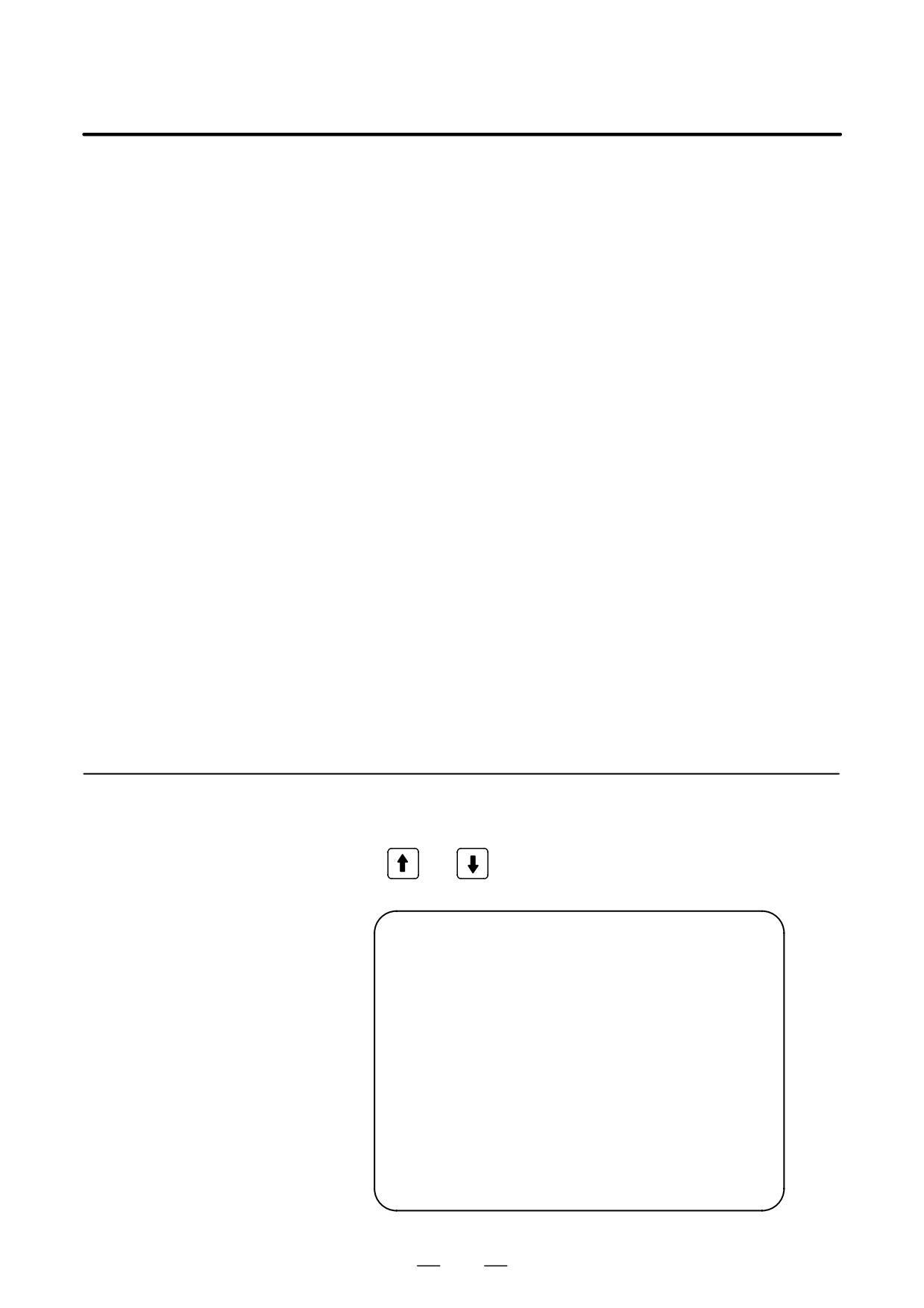
shown below. The user can switch between the two screens with the page
Screen
keys
and
(AMPLIFIER SETTING)
O1000 N00001
1
X A1-L
α SVM-HV
2
40AL
2
Y A1-M
α
SVM
2
12A
3
Z A2-L
β
SVM
1
40A
4
A A3-L
α
SVM
2
20A
5
B A3-M
α
SVM
2
40A
6
C A4-L
α
SVU
1
240A
MDI **** *** ***
13:11:56
[ AMP
][ AXIS
][ MAINT ][
][ (OPRT) ]
1000
G. FSSB START-UP PROCEDURE/
B-63525EN/02
APPENDIX
MATERIALS
(AMPLIFIER MAINTENANCE)
O1000 N00001
NO.
1
X
01A
970123
01
2
Y
01A
970123
01
3
Z
01A
970123
01
4
A
02B
970123
01
5
B
02B
970123
01
6
C
02B
970123
01
MDI **** *** ***
13:11:56
[ AMP
][ AXIS
][ MAINT ][
][ (OPRT) ]
The amplifier maintenance screens display the following items:
D AXIS NO:
Controlled axis number
D NAME:
Controlled axis name
D AMP:
Type of an amplifier connected to each axis
D SERIES:
Series of a servo amplifier connected to each axis
D UNIT:
Unit type of a servo amplifier connected to each
axis
D NO. OF AXES: Maximum number of axes of an amplifier
connected to each axis
D CURRENT:
Maximum current value of an amplifier connected
to each axis
D VERSION:
Version of an amplifier unit connected to each axis
D TEST:
Test date of an amplifier connected to each axis
Example) 010123: January 23, 2001
D MAINTENANCE: Engineering change drawing number of an
amplifier connected to each axis
1001
H. NOTATION OF MDI KEYS
APPENDIX
B-63525EN/02
NOTATION OF MDI KEYS
H
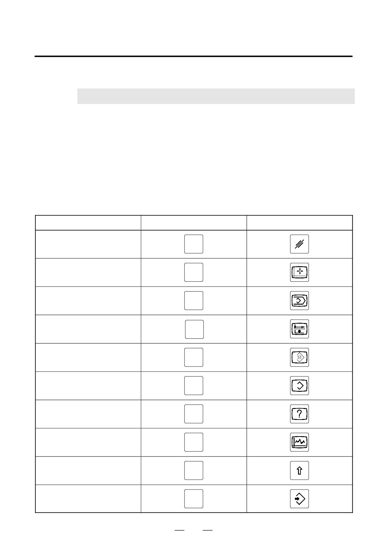
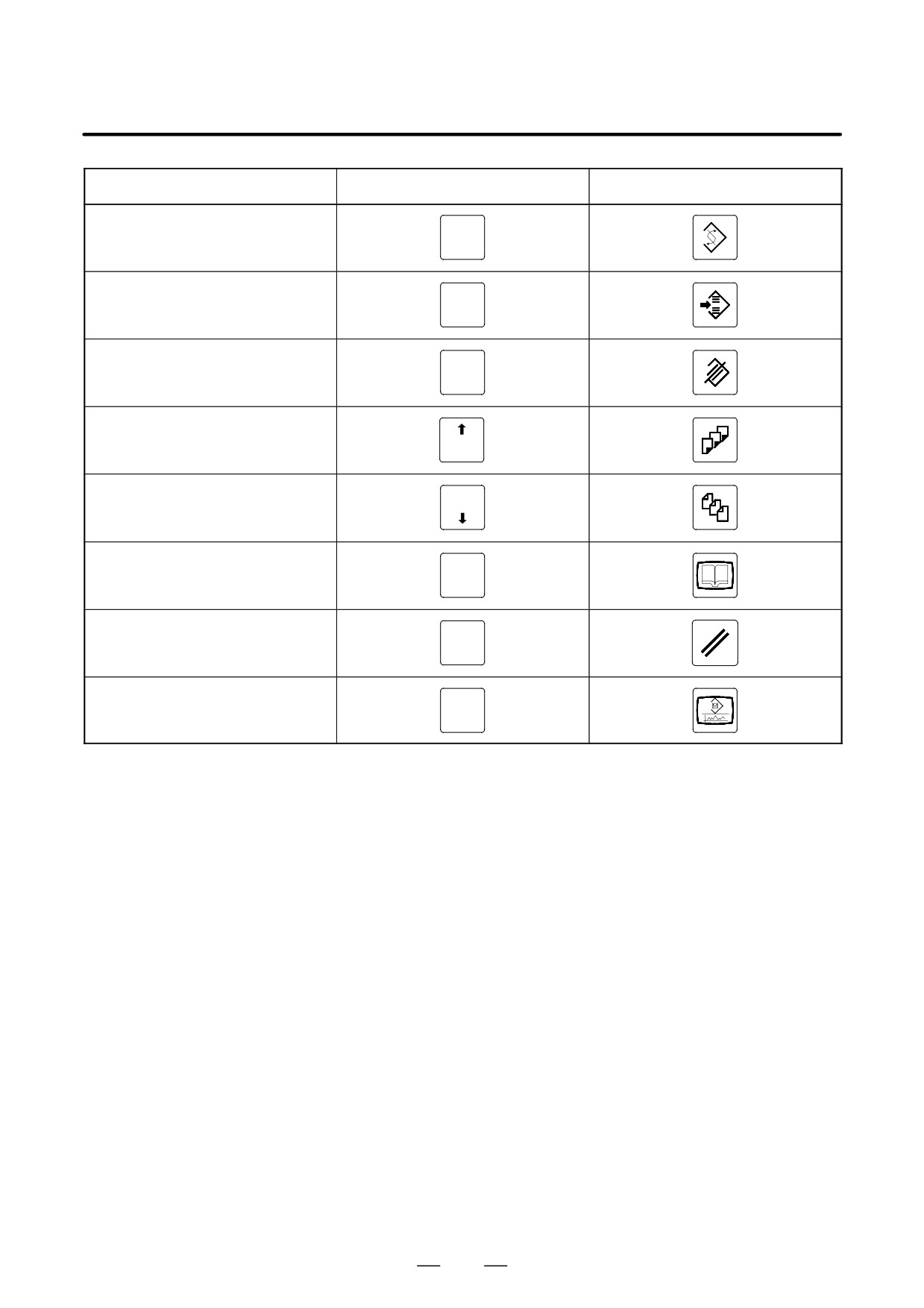
i series CNC have two types of MDI keypads : English type and Symbolic type.
The table below shows correspondence between English keys and Symbolic keys.
This manual uses English type in the text.
Therefore when a user uses Symbolic type MDI keypads and encounters an English key in the text, please refer
to the correspondence table shown below.
Name
English key
Symbolic key
CANCEL key
CAN
POSITION key
POS
PROGRAM key
PROG
OFFSET/
OFFSET
SETTING key
SETTING
CUSTOM key
CUSTOM
SYSTEM key
SYSTEM
MESSAGE key
MESSAGE
GRAPH key
GRAPH
SHIFT key
SHIFT
INPUT key
INPUT
1002
B-63525EN/02
APPENDIX
H. NOTATION OF MDI KEYS
Name
English key
Symbolic key
ALTER key
ALTER
INSERT key
INSERT
DELETE key
DELETE
PAGE UP key
PAGE
PAGE
PAGE DOWN key
HELP key
HELP
RESET key
RESET
CUSTOM
CUSTOM/GRAPH key
GRAPH
1003