FANUC Series 0i-MODEL D, Series 0i Mate-MODEL D. OPERATOR'S MANUAL - page 24
12.SETTING AND DISPLAYING DATA OPERATION
B-64304EN/02
12996
(7th) G code modal group to be recorded in the history when an alarm is issued
[Input type] Parameter input
[Data type] Byte path
[Valid data range] 1 to the maximum number of G code groups
Set the number of a G code modal group to be recorded in the alarm history and operation
history when an alarm is issued.
* If a value beyond the valid data range is set, the status of group 07 is recorded.
12997
(8th) G code modal group to be recorded in the history when an alarm is issued
[Input type] Parameter input
[Data type] Byte path
[Valid data range] 1 to the maximum number of G code groups
Set the number of a G code modal group to be recorded in the alarm history and operation
history when an alarm is issued.
* If a value beyond the valid data range is set, the status of group 08 is recorded.
12998
(9th) G code modal group to be recorded in the history when an alarm is issued
[Input type] Parameter input
[Data type] Byte path
[Valid data range] 1 to the maximum number of G code groups
Set the number of a G code modal group to be recorded in the alarm history and operation
history when an alarm is issued.
* If a value beyond the valid data range is set, the status of group 09 is recorded.
12999
(10tht) G code modal group to be recorded in the history when an alarm is issued
[Input type] Parameter input
[Data type] Byte path
[Valid data range] 1 to the maximum number of G code groups
Set the number of a G code modal group to be recorded in the alarm history and operation
history when an alarm is issued.
* If a value beyond the valid data range is set, the status of group 10 is recorded.
Screen display
To display the operation history screen, set bit 4 (OPH) of parameter No. 3106 to 1.
Procedure
1
Press function key
2
Press continuous menu key
several times until soft key [OPERAT HISTRY] ([OPEHIS] for
the 8.4-inch display unit) is displayed.
3
Press soft key [OPERAT HISTRY], then press newly displayed soft key [OPERAT HISTRY]. The
operation history screen is then displayed.
4
To display the previous page and next page of the operation history, use page keys
and
To display a part across two pages, use the cursor keys
and
. The screen display is
shifted by half page.
(With the 8.4-inch display devices, the screen display is shifted by one column.)
By pressing soft key [(OPRT)] on the operation history screen, it becomes possible to perform the
following soft key operations:
- 666 -
B-64304EN/02
OPERATION 12.SETTING AND DISPLAYING DATA
a
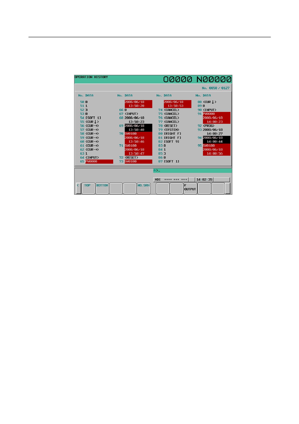
[TOP] displays the starting page (the oldest data).
b
[BOTTOM] displays the end page (the latest data).
c
[NO.SRH] displays specified operation history data.
(Example) Specifying 50 then [NO.SRH] displays the 50th data.
Fig. 12.4.13.3 (a) Operation history screen
Displayed information
1
Serial number and display start history number/total number of history data items
A serial number is indicated on the left side of each recorded history data item. A smaller serial
number indicates an older data item.
In the upper right part of the screen, the display start history number and the total number of history
data items are indicated. The total number of history data items does not include history data items
not displayed on the screen.
2
Data
•
MDI key
When bit 5 (HKE) of parameter No. 3195 is set to 0, key operations are recorded.
A key operation is indicated following a path number (for example, "1_[LEFT F]", and
"2_[LEFT F]"). (When only one path is used, the path number is not indicated.)
P_ used in "P_[LEFT F]", for example, indicates a key operation made from the outside.
i
Address keys and numeric keys
Characters such as A to Z, 0 to 9, ;, +, and - are indicated directly.
These characters are displayed in black.
ii
Function menu keys, operation menu keys, and soft keys
These keys are enclosed in brackets [] (for example, "[LEFT F]", "[SOFT 1]" to "[SOFT
10]", and "[RIGHT F]"). These keys are displayed with green characters.
iii
Function keys, page keys, cursor keys, and so on
These keys are enclosed in angle brackets <> (for example, "<POS>", "<SYSTEM>",
"<PAGE ↑>", "<CUR →>", "<RESET>", and "<INPUT>"). These keys are displayed
with green characters.
iv Power-on key
This key is displayed with white characters in the green background.
- 667 -
12.SETTING AND DISPLAYING DATA OPERATION
B-64304EN/02
•
I/O signals
When bit 6 (HDE) of parameter No. 3195 is set to 0, I/O signals specified on the operation
history signal selection screen are recorded. Recorded signals are indicated on a bit-by-bit
basis with information about the signal address and a change in bit. These signals are displayed
with purple characters.
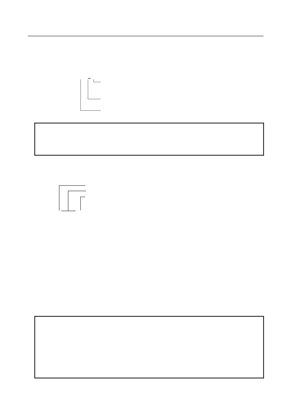
G000.2 ω
Change from 0 to 1 is indicated by ↑.
Change from 1 to 0 is indicated by ↓.
Indicates a bit.
Indicates the address of a signal.
NOTE
1 When more than one bit at the same address changes at the same time, the
changes of these bits are treated as one history data item.
2 A signal fluctuation for less than 8 msec is not recorded as history data.
•
Alarms
Alarm numbers and the issuance times are displayed on the operation history screen.
This alarm information is displayed with white characters in the red background.
Indicates the path number.
Indicates the alarm number.
For the servo axis type, indicates the servo axis name.
For the spindle type, indicates the spindle name or
spindle number.
1_OT0506 ( XA1)
2008/01/11 Indicates the date and time of issuance in two lines.
11:22:33
When a path name, axis name, or spindle name was changed after the issuance of an alarm, the
alarm is indicated with a newly assigned name.
•
Time and date
The time and date of the following are displayed in two lines:
i
The time and date of power-on. These are displayed with white characters in the green
background.
ii
The time and date of power-off. These are displayed with green characters.
iii
Date on which the date changed. This is displayed with black characters.
iv
Date and time at regular intervals of the period set in parameter No. 3122. These are
displayed with black characters.
v Date and time when history data was erased. These are displayed with black characters.
NOTE
1 For item iv (recording time at regular intervals) above, if there is no operation to
be recorded within a certain period, the time is not recorded. For item iii (date
on which the date changed) above, however, it is assumed that there is a data
item to be recorded and item iv (recording time at regular intervals) above is also
recorded.
2 When the date and time in the CNC system are changed, the date and time at
which the change is made may be recorded as the date and time in iii or iv
above.
- 668 -

B-64304EN/02
OPERATION 12.SETTING AND DISPLAYING DATA
History data not displayed on the screen
In addition to history data of MDI keys, I/O signal status, alarms issued, external operator messages (not
displayed on the operation history screen), and time stamps, data described below can be recorded with
time. Such history data cannot be displayed on the screen but can be output to external input/output
devices. (See Subsection 12.4.15.5, "Outputting all history data".)
1
Detailed data at alarm issuance
If bit 7 (HAL) of parameter No. 3196 is set to 0, 10 modal G codes, auxiliary function codes D, E, F,
H, M, N, O, S, and T, absolute coordinates, and machine coordinates in the block being executed
when an alarm was issued are recorded together with the alarm number and the time of alarm
issuance.
The group numbers of the 10 modal G codes to be recorded are set in parameter Nos. 12990 to
12999. If these parameters are not specified, modal G codes of groups 01 to 10 are recorded.
NOTE
To record as many items as possible instead of recording detailed data at alarm
issuance, set bit 7 (HAL) of parameter No. 3196 to 1.
2
External alarm messages and macro alarm messages
If bit 3 (EAH) of parameter No. 3112 is set to 1, external alarm messages and macro alarm messages
can also be recorded as history data.
NOTE
To record also external alarm and macro alarm messages as history data, set bit
3 (EAH) of parameter No. 3112 to 1, and at the same time set bit 7 (HAL) of
parameter No. 3196 to 0.
3
Modification of tool offset data
If bit 0 (HTO) of parameter No. 3196 is set to 1, when tool offset data is modified, the number and
type of the tool offset are recorded as well as the tool offset data before modification, the tool offset
data after modification, and the time of modification.
4
Modification of workpiece offset/workpiece shift (T series) data
If bit 1 (HWO) of parameter No. 3196 is set to 1, when workpiece offset data is modified, the
number of the modified workpiece offset is recorded as well as the workpiece offset data before
modification, the workpiece offset data after modification, and the time of modification. Similar data
is recorded also when workpiece shift amounts (T series) are modified.
5
Modification of parameters
If bit 2 (HPM) of parameter No. 3196 is set to 1, when a parameter is modified, the number and type
(axis type, spindle type, path type, or machine group type) of the parameter are recorded as well as
the parameter data before modification, the parameter data after modification, and the time of
modification.
NOTE
Modifications made at power-on and modifications of passwords and keys are not
recorded as history data.
6
Modification of custom macro common variables (#100 to #999)
If bit
3 (HMV) of parameter No. 3196 is set to 1, when a custom macro common variable is
modified, the number of the common variable is recorded as well as the common variable value
before modification, the common variable value after modification, and the time of modification.
- 669 -
12.SETTING AND DISPLAYING DATA OPERATION
B-64304EN/02
Erasing history data from the operation history screen
Procedure
1
Display the operation history screen.
2
Press soft key [(OPRT)].
3
Press soft key [ALL CLEAR].
4
Press soft key [EXEC]. Operation history data is erased.
12.4.13.4 Selecting operation history signals
I/O signals to be recorded as history data can be selected. Up to 60 signals can be set to select signals.
Setting data
1
Press function key
2
Press continuous menu key
several times until soft key [OPERAT HISTRY] is displayed.
3
Press soft key [OPERAT HISTRY].
4
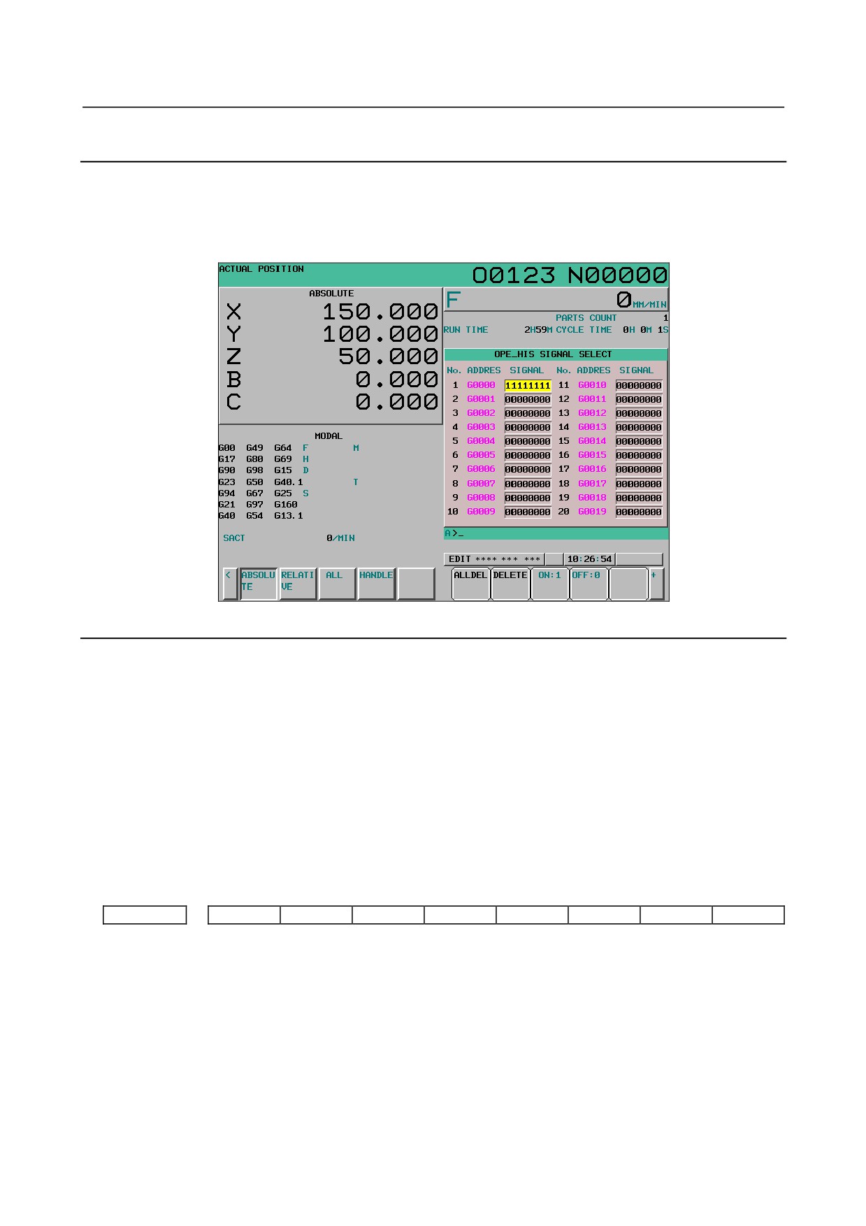
Press soft key [SIGNAL SELECT] to display the operation history signal selection screen.
5
Press soft key [(OPRT)].
6
Move the cursor to a desired position by using cursor keys
and
7
Type a signal type (X, G, F, or Y) and an address, then press
Example:
When G0004 is entered then
is pressed:
The entered signal address, G0004, is set in ADDRESS, and initial value 00000000 is set in
SIGNAL.
8
Select the bits to be recorded in the history.
To change the status of all bits of the specified signal address, place the cursor in all bits so that the
bits are highlighted (for example, "00000000"), then press soft key [ON:1] or [OFF:0]. Then, the bits
are set to 11111111 or 00000000.
To change the status of only a certain bit, move the cursor to the bit by using cursor keys
and
, and press [ON:1] or [OFF:0]. The selected bit is then set to 1 or 0.
9
Up to 60 addresses can be set to select signals. Addresses need not necessarily be set sequentially
starting from No. 1.
NOTE
1 While the operation history signal selection screen is being displayed, recording
of history data is not performed.
2 Only X, Y, G, and F can be set for I/O signals.
For data not set, "********" is displayed.
3 Even when an address is set, history data is not recorded if all bits are set to 0.
4 When the ON/OFF width of an input signal is less than 8 msec, recording of
history data is not performed. Also, there are some signals that are not recorded.
5 When many signals are selected, the processing speed may lower.
Clearing the selection of each signal
1
Display the operation history signal selection screen.
2
Move the cursor to the data to be cleared.
3
Press soft key [DELETE].
- 670 -
B-64304EN/02
OPERATION 12.SETTING AND DISPLAYING DATA
4
Press soft key [EXEC].
Clearing the selection of all signals
1
Display the operation history signal selection screen.
2
Press soft key [ALLDEL].
3
Press soft key [EXEC].
Fig. 12.4.13.4 (a) Operation history signal selection screen
Selection with parameters
If bit 4 (PHS) of parameter No. 3206 is 1, selection of input/output signals to be recorded as history data
can be made with parameters.
In this case, if a signal is selected or deselected on the operation history signal selection screen, the value
of the corresponding parameter is automatically changed. If the value of a parameter is changed on the
parameter screen, the display on the operation history signal selection screen is also changed.
The same applies to input operations. If operation history signal selection data is input on the operation
history signal selection screen, the value of the corresponding parameter is automatically changed. If a
parameter is input on the parameter screen, the display on the operation history signal selection screen is
also changed.
Only the first 20 of the 60 data items can be selected with parameters.
Parameter setting
#7
#6
#5
#4
#3
#2
#1
#0
3206
PHS
[Input type] Parameter input
[Data type] Bit
#4 PHS Operation history signal selection:
0: Does not interact with parameters.
Operation history signal selection is added or deleted on the operation history signal
selection screen.
Changing the settings of parameters Nos. 12801 to 12820, Nos. 12841 to 12860, or
Nos. 12881 to 12900 has no effect on operation history signal selection.
Changes to the signals of the addresses specified by parameters Nos. 12801 to 12820,
Nos. 12841 to 12860, or Nos. 12881 to 12900 are not recorded in the history.
- 671 -
12.SETTING AND DISPLAYING DATA OPERATION
B-64304EN/02
1: Interacts with parameters.
Operation history signal selection can be performed either on the operation history
signal selection screen or by setting parameters.
NOTE
Setting this parameter to 1 reflects the current operation history
signal selection data on parameters Nos. 12801 to 12900.
12801
Operation history signal selection address type (No.01)
to
to
12820
Operation history signal selection address type (No.20)
[Input type] Parameter input
[Data type] Byte
[Valid data range] 0 to 4
These parameters set operation history signal selection address types Nos. 1 to 20.
The correspondence between address types and settings is as given in the table below.
Address type
Parameter value
Not selected.
0
X
1
G
2
Y
3
F
4
Nos. 1 to 20 correspond to Nos. 1 to 20 on the operation history signal selection screen.
These parameters are paired with other parameters as given below.
No.
Address type
Address number
Bit number
01
No. 12801
No. 12841
No. 12881
02
No. 12802
No. 12842
No. 12882
03
No. 12803
No. 12843
No. 12883
…
…
…
…
20
No. 12820
No. 12860
No. 12900
NOTE
1 Operation history signals that can be selected and deselected with
parameters are for the first 20 of 60 sets.
2 To deselect a signal, set 0.
At this time, 0 is set as the initial value in the address number (Nos.
12841 to 12860) and the bit number (Nos. 12881 to 12900)
corresponding to that signal.
3 When an address type is set, 0 is set as the initial value in the
address number (Nos. 12841 to 12860) and the bit number (Nos.
12881 to 12900).
[Example]
If parameter No. 12801 is set to 2, the parameters are initialized
as follows:
No. 12841=0
Address number
No. 12881=00000000
Bit number
4 If an attempt is made to set a value that cannot be set, a warning,
"DATA IS OUT OF RANGE" appears; retry setting a value.
- 672 -
B-64304EN/02
OPERATION 12.SETTING AND DISPLAYING DATA
12841
Operation history signal selection address number (No.01)
to
to
12860
Operation history signal selection address number (No.20)
[Input type] Parameter input
[Data type] Word
[Valid data range] For an explanation of the address ranges of the G, F, X, and Y signals, refer to the PMC
Programming Manual (B-64393EN).
These parameters set operation history signal selection address numbers Nos. 1 to 20.
Nos. 1 to 20 correspond to Nos. 1 to 20 on the operation history signal selection screen.
These parameters are paired with other parameters as given below.
No.
Address type
Address number
Bit number
01
No. 12801
No. 12841
No. 12881
02
No. 12802
No. 12842
No. 12882
03
No. 12803
No. 12843
No. 12883
…
…
…
…
20
No. 12820
No. 12860
No. 12900
NOTE
1 Operation history signals that can be selected and deselected with
parameters are for the first 20 of 60 sets.
2 When an address number is set, 0 is set as the initial value in the
bit number (Nos. 12881 to 12900) corresponding to that signal.
3 If an attempt is made to set a value that cannot be set or if the
address type (Nos. 12801 to 12820) corresponding to that signal is
0, a warning, "DATA IS OUT OF RANGE" appears; retry setting a
value.
#7
#6
#5
#4
#3
#2
#1
#0
12881
RB7
RB6
RB5
RB4
RB3
RB2
RB1
RB0
to
to
12900
RB7
RB6
RB5
RB4
RB3
RB2
RB1
RB0
[Input type] Parameter input
[Data type] Bit
RB7 - RB0 History of the respective operation history signal selection bits Nos. 1 to 20 (RB7 to RB0)
corresponding to the operation history signal selection addresses set in parameters Nos.
12801 to 12860 is:
0 : Not retained. (History of the bit is not recorded.)
1 : Retained. (History of the bit is recorded.)
These parameters are paired with other parameters as given below.
No.
Address type
Address number
Bit number
01
No. 12801
No. 12841
No. 12881
02
No. 12802
No. 12842
No. 12882
03
No. 12803
No. 12843
No. 12883
…
…
…
…
20
No. 12820
No. 12860
No. 12900
NOTE
1 Operation history signals that can be selected and deselected with
parameters are for the first 20 of 60 sets.
- 673 -

12.SETTING AND DISPLAYING DATA OPERATION
B-64304EN/02
NOTE
2 If the value of the address type (Nos. 12801 to 12820)
corresponding to that signal is 0, a warning, "DATA IS OUT OF
RANGE" appears; retry setting a value.
12.4.13.5 Outputting all history data
All history data (operation history data, alarm history data, and operator message history data) can be
output to external input/output devices.
It is impossible, however, to output history data individually.
Procedure
1
Make an output device ready for output.
2
Set the EDIT mode.
3
Press function key
4
Press continuous menu key
several times until soft key [OPERAT HISTRY] ([OPEHIS] for
the 8.4-inch display unit) is displayed.
5
Press soft key [OPERAT HISTRY], then press newly displayed soft key [OPERAT HISTRY]. The
operation history screen is displayed.
6
Press soft key [(OPRT)].
7
Press soft key [F OUTPUT].
8
Enter a file name, and press soft key [EXEC].
When soft key [EXEC] is pressed without entering a file name, the output file name is assumed to be
OPRT_HIS.TXT.
Output format
History data is output as an ASCII file in the following format:
1
MDI keys
After "MDI", "path-number_", "key-data", and "input-time" are output in this order.
(Key data input at power-on is indicated as "Power on MDI".)
<Example>
MDI 01_A 12:23:34
MDI 02_<CAN> 12:23:34
MDI 02_[SOFT HF1] 12:23:35
MDI P_<RESET> 12:34:56
Power on MDI 01_<RESET> 12:34:56
2
I/O signals
After "DI/DO", "PMC-number_", "signal-address_bit-status", and "time-of-change" are output in
this order.
<Example>
DI/DO 1_F0002.2_on 12:34:56
DI/DO 1_ G0043.0_off G0043.1_off 12:35:00
(For multiple bits at the same address)
3
Alarms
After "Alarm", "path-number_", "type", "alarm-number", "G-code-modal-data",
"modal-data-other-than-G-code", "absolute-coordinate-value" and "machine-coordinate-value" for
each axis, and "date-and-time-of-alarm-issuance" are output in this order.
An asterisk "*" is output before the modal data that was specified in a block executed when the
alarm was issued.
- 674 -
B-64304EN/02
OPERATION 12.SETTING AND DISPLAYING DATA
<Example>
•
Alarm 01_SR01973
*G0. G97. G69. G99. G21. G50.2 G25. G13.1 B0. D0. E0. *F100. H0. M10. *N123. Test_
S1000. T1010.
X1 ABS 197.999 MCN 197.999 Y1 ABS -199806.00 MCN -199806.00 Z1 ABS 297.009
MCN 0.123 C1 ABS 10395.999 MCN 0.000 at 2007/09/01 19:03:28
•
Alarm 02_ OT00506(ZA2)
*G1. G17. G90. G22. G94. G20. *G42. G49. G80. G12.1 B0. *D12. E0. *F100. H34. M0.
*N123. O123 S0. T0.
X2 ABS 123.999 MCN 234.000 Y2 ABS -123.00 MCN -234.00 ZA2 ABS 1234.567 MCN
-1234.567 at 2007/09/01 12:34:56
•
When additional information is not to be recorded when an alarm is issued (bit 7 (HAL) of
parameter No.
3196 is set to
1), only "path-number_", "alarm-number", and
"date-and-time-of-alarm-issuance" are output.
Alarm 01_OT00506(XC1) at 2007/09/01 22:08:32
Alarm 02_SW00100 at 2007/09/01 19:07:52
•
When external alarm/macro alarm messages are to be recorded (bit 7 (HAL) of parameter No.
3196 is set to 0) and bit 3 (EAH) of parameter No. 3112 is set to 1, the messages are also
output.
Alarm 01_MC00001 Message ATC ALARM
G0. G97. G69. G99. G21. G40. G25. G22. G80. D0. E0. F0. H0. M0. N0. O9999 S0. T0.
X2 ABS 10.000 MCN 0.000Y2 ABS 123.000 MCN 0.000Z2 ABS 0.000 MCN 0.000 at
2007/09/01 10:06:43
4
External operator messages
After "EXT_Message", "message-number", "message", and "date-and-time-of-issuance" are output
in this order.
<Example>
EXT_Message 01234 OIL PRESSURE DECREASE at 2007/09/01 2:38:43
5
Modification of tool offset data
After "Tool Offset", "path-number_", "type", "offset-number", "offset-data-before-modification",
"offset-data-after-modification", and "time-of-modification" are output in this order. The following
types are provided:
Common to M/T
:
G=Geometric compensation
W=Wear compensation
M series
:
H=Tool length compensation
D=Cutter compensation
T series
:
R=Tool-nose radius compensation
T=Tool nose direction
<Example>
Tool Offset 01_X0002 0.000 → 1 at 12:15:43
Tool Offset 02_XW0001 -9999.999 → 9999.999 at 12:15:46
Tool Offset 01_RG0032 0.000 → 0.003 at 12:15:52
Tool Offset 02_T0001 5. → 2. at 19:34:11
Tool Offset 02_W0123 -10.000 → 123.456 at 10:28:58
Tool Offset 01_HG0456 0.000 → 999.999 at 11:37:40
Tool Offset 01_
0064 12.340 → 12.569 at 11:39:42
6
Modification of workpiece offset/workpiece shift (T series) data
After "Work Offset", "EXT Work Offset", or "Work Shift", "path-number_(axis-name)", "type",
"offset-number",
"offset-data-before-modification",
"offset-data-after-modification",
and
"time-of-modification" are output in this order.
<Example>
Work Offset 01_G55(XA1) 15.000 → 0.007 at 09:23:03
Work Offset 02_EXT(Z2) 0.000 → 300.003 at 09:22:50
EXT Work Offset 02_G54.1P300 (Y2) 123.456 → 9999.999 at 12:15:46
- 675 -
12.SETTING AND DISPLAYING DATA OPERATION
B-64304EN/02
Work Shift (X) 02_999999.999 → 999999.999 at 10:22:37
7
Modification
of
parameters
After
"Parameter",
"type",
"parameter-number",
"parameter-before-modification", "parameter-after-modification", and "time-of-modification" are
output in this order.
The following types are provided:
Path type
: L is added before the path number.
Axis type
: A is added before the axis number.
Spindle type
: S is added before the spindle number.
Machine group type : Indicated as the machine type. T is added before the machine group number.
Others
: No type is output.
<Example>
Parameter N03112
00000100 → 00001100 at
11:18:40
Parameter Path type N01410 L02
0.000 → 1000.000 at
18:58:48
Parameter Axis type N01423 A04(B2)
0.000 → 10000.000 at
18:58:48
Parameter Spindle type N04011 S1(S)
10011010 → 10011010 at
18:58:53
Parameter Machine type N06310 T01
0 → -32768 at
19:21:13
8
Modification of custom macro common variables (#100 to #999)
After
"Macro
variable",
"path-number_",
"#variable-number",
"common-variable-value-before-modification", "common-variable-value-after-modification", and
"time-of-modification" are output in this order.
Variable values are output in the data format M × (10**(-E)).
<Example>
•
When #149 on the first path was modified from <empty> to 12.345
Macro variable 01_#149 Empty → 123450000*(10**-7) at 15:02:35
•
When #549 on the second path was modified from -12.345 to 123456789012
Macro variable 02_#549 -123450000*(10**-7) →123456789*(10**3) at 15:03:27
9
Date and time
Power on at 2008/02/01 17:11:17
(Date and time of power-on)
Power off at 2008/02/01 17:49:17
(Date and time of power-off)
Date 2008/02/01 00:00:00
(Record indicating a change in date)
Time stamp at 2008/02/01 15:51:00
(Record at regular intervals)
Data delete at 2008/02/01 10:56:18
(Date and time when history data was deleted)
- 676 -
B-64304EN/02
OPERATION 12.SETTING AND DISPLAYING DATA
Example of output
%
===============
OPERATION HISTORY ===============
Data delete at 2000/01/23 12:34:01
MDI 01_<RESET> 12:34:02
MCR_Message MACRO MESSAGE at 2000/01/23 12:34:03
Alarm 01_MC03001 Message MACRO ALRM
G0.G97.G69.G99.G21.G40.G25.G22.G80. D0.E0.F0.H0.M0.N0.O1234 S0.T0.
X1 ABS 0.005 MCN 0.000 Z1 ABS 0.010 MCN 0.000 at 2000/01/23 12:34:04
MDI 01_<SYSTEM> 12:34:05
MDI 01_[RIGHT F] 12:34:06
MDI 01_[RIGHT F] 12:34:07
MDI 01_[RIGHT F] 12:34:08
MDI 01_[SOFT HF9] 12:34:09
DI/DO
1_ G0043.1_on 12:34:10
Alarm 01_SR01973
G0.G97.G69.G99.G21.G40.G25.G22.G80. D0.E0.F0.H0.M0.N0.O1234 S0.T0.
X1 ABS 0.005 MCN 0.000 Z1 ABS 0.010 MCN 0.000 at 2000/01/23 12:34:11
MDI 01_<RESET> 12:34:12
EXT_Message 02001 EXT MESSAGE at 2000/01/23 12:34:13
===============
ALARM HISTORY ===============
Alarm 01_MC03001 Message MACRO ALRM at 2000/01/23 12:34:04
Alarm 01_SR01973 at 2000/01/23 12:34:11
=========
OPERATION MESSAGE HISTORY =========
MCR_Message MACRO MESSAGE at 2000/01/23 12:34:03
EXT_Message 02001 EXT MESSAGE at 2000/01/23 12:34:13
%
- 677 -
12.SETTING AND DISPLAYING DATA OPERATION
B-64304EN/02
12.5 SCREENS DISPLAYED BY FUNCTION KEY
Function key
can be pressed to display alarms, alarm history, operator messages, or external
operator message history, etc.
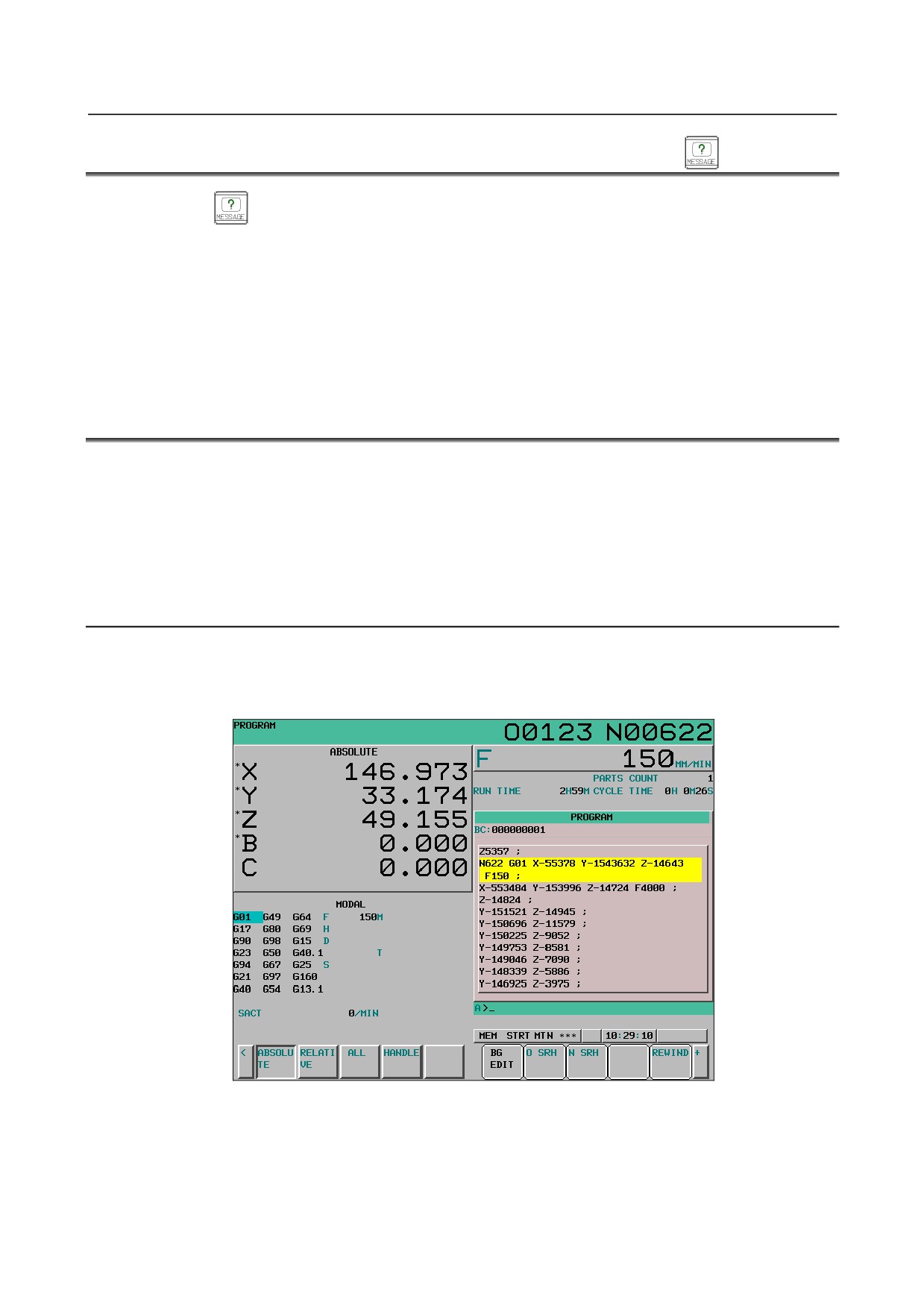
For alarms, see III-7.1. For alarm history and external operator message history, see III-12.4.13.
For operator messages, refer to the manual provided by the machine tool builder.
12.6 DISPLAYING THE PROGRAM NUMBER, SEQUENCE
NUMBER, AND STATUS, AND WARNING MESSAGES
FOR DATA SETTING OR INPUT/OUTPUT OPERATION
The program number, sequence number, and current CNC status are always displayed on the screen
except when the power is turned on, a system alarm occurs.
If data setting or the input/output operation is incorrect, the CNC does not accept the operation and
displays a warning message.
This section describes the display of the program number, sequence number, and status, and warning
messages displayed for incorrect data setting or input/output operation.
12.6.1 Displaying the Program Number and Sequence Number
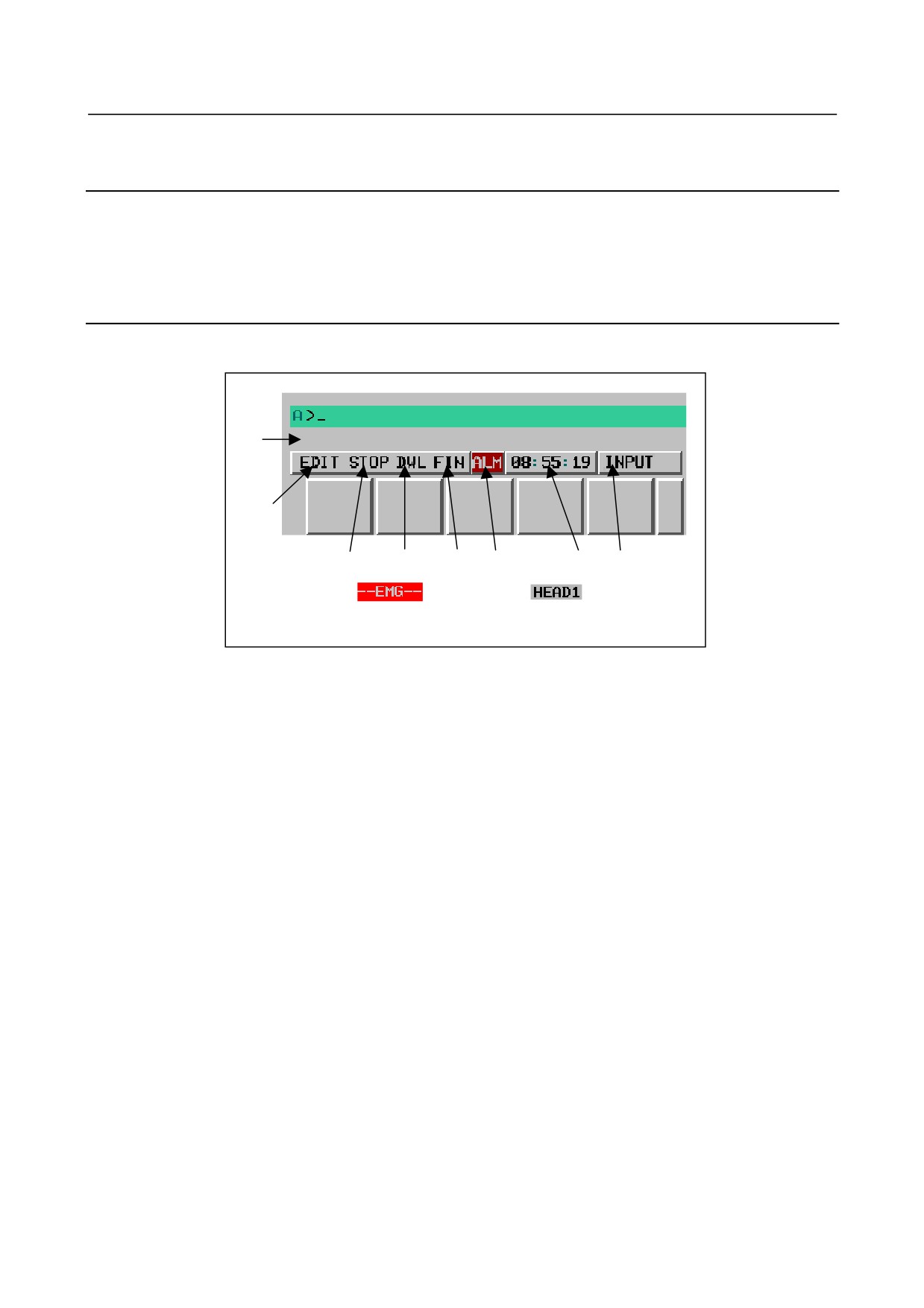
The number of the program currently selected or currently executed and the current sequence number are
indicated in the upper right part as shown below.
Program number Sequence number
Fig. 12.6.1 (a) Program number and sequence number (10.4-inch)
In the EDIT mode, the number of the program currently edited in the foreground are indicated.
- 678 -
B-64304EN/02
OPERATION 12.SETTING AND DISPLAYING DATA
12.6.2 Displaying the Status and Warning for Data Setting or
Input/Output Operation
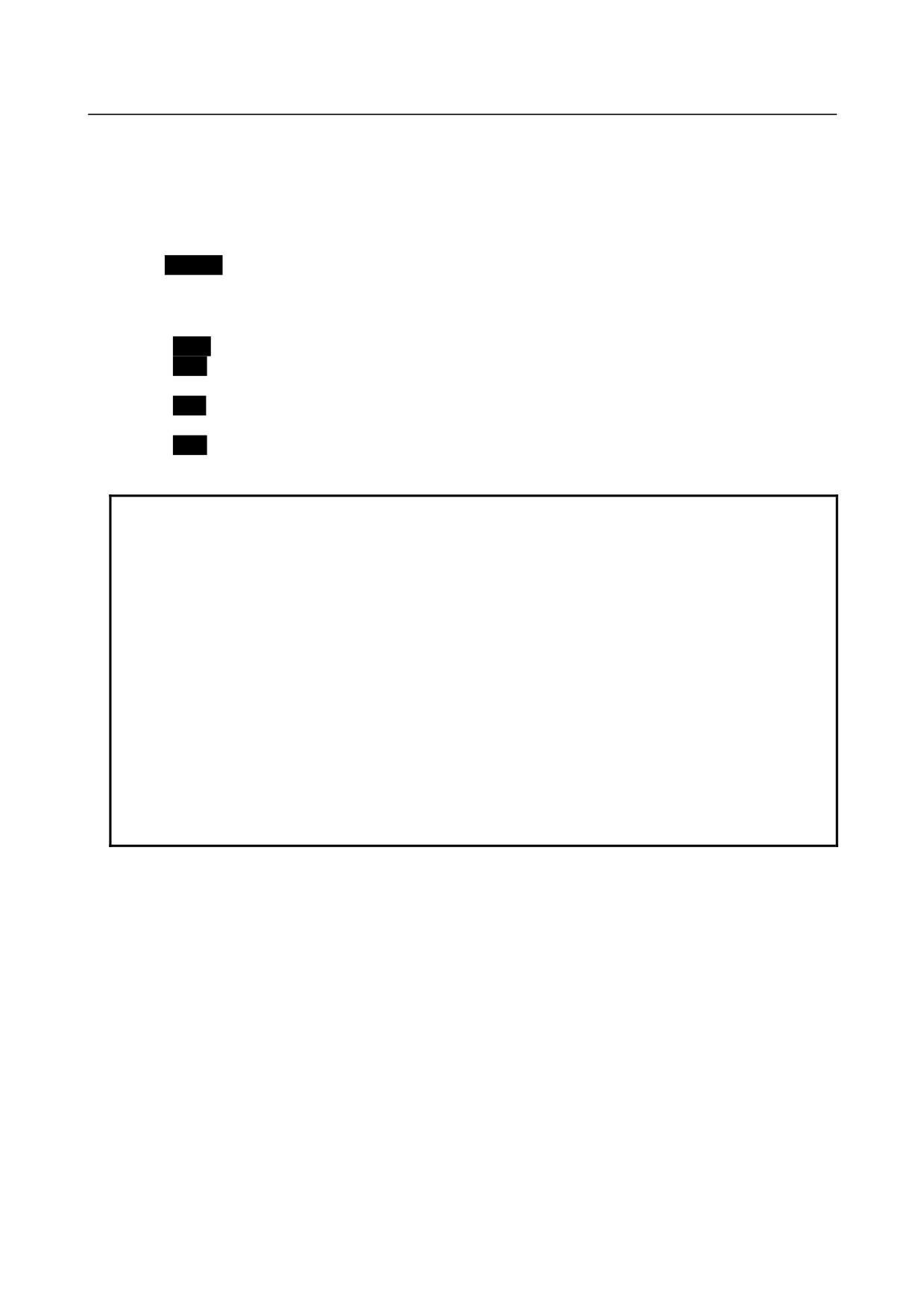
The current mode, automatic operation state, alarm state, and program editing state are displayed on the
next to last line on the screen allowing the operator to readily understand the operation condition of the
system. If data setting or the input/output operation is incorrect, the CNC does not accept the operation
and a warning message is displayed on the next to last line of the screen. This prevents invalid data
setting and input/output errors.
Explanation
-
Description of each display
(9)
DATA IS OUT OF RANGE
(1)
(2)
(3)
(4)
(6)
(7)
(8)
(5) :
(10) :
(5) is displayed in the
(10) is displayed at the position
area for (3) and (4).
where (8) is now displayed.
Fig. 12.6.2 (a) Positions of status indications
(1) Current mode
MDI
:
Manual data input, MDI operation
MEM
:
Automatic operation (memory operation)
RMT
:
Automatic operation (DNC operation, or such like)
EDIT
:
Memory editing
HND
:
Manual handle feed
JOG
:
Jog feed
INC
:
Manual incremental feed
REF
:
Manual reference position return
****
:
Modes other than the above.
(2) Automatic operation status
****
:
Reset (When the power is turned on or the state in which program execution
has terminated and automatic operation has terminated.)
STOP
:
Automatic operation stop (The state in which one block has been executed and
automatic operation is stopped.)
HOLD
:
Feed hold (The state in which execution of one block has been interrupted and
automatic operation is stopped.)
STRT
:
Automatic operation start-up
(The state in which the system operates
automatically)
(3) Axis moving status/dwell status
MTN
:
Indicates that the axis is moving.
DWL
:
Indicates the dwell state.
***
:
Indicates a state other than the above.
- 679 -
12.SETTING AND DISPLAYING DATA OPERATION
B-64304EN/02
(4) State in which an auxiliary function is being executed
FIN
:
Indicates the state in which an auxiliary function is being executed. (Waiting
for the complete signal from the PMC)
***
:
Indicates a state other than the above.
(5) Emergency stop or reset status
--EMG--
:
Indicates emergency stop.(Blinks in reversed display.)
-RESET-
:
Indicates that the reset signal is being received.
(6) Alarm status
ALM
:
Indicates that an alarm is issued. (Blinks in reversed display.)
BAT
:
Indicates that the voltage of the lithium battery (the backup battery of the CNC)
has decreased. (Blinks in reversed display.)
APC
:
Indicates that the voltage of the backup battery of the absolute pulse coder has
decreased. (Blinks in reversed display.)
FAN
:
Indicates that the rotation speed of the fan has decreased. (Blinks in reversed
display.)
NOTE
When the FAN in the αi servo amplifier or the αi spindle amplifier falls into the
warning state or the number of rotations of the FAN built into the stand-alone
type control unit decreases, FAN is displayed blinking.
Refer to "Chapter of αi SERVO WARNING INTERFACE in MAINTENANCE
MANUAL(B-64305EN)" or "Chapter of SERVO WARNING INTERFACE in
CONNECTION MANUAL(FUNCTION) (B-64303EN-1)" for details and measures
concerning the warning state of FAN in the αi servo amplifier.
Refer to "Chapter of WARNING INTERFACE in MAINTENANCE MANUAL
(B-64305EN)" or " Chapter of SPINDLE WARNING INTERFACE in
CONNECTION MANUAL(FUNCTION) (B-64303EN-1)" for details and measures
concerning the warning state of FAN in the αi spindle amplifier.
When not corresponding to the above, it is thought that the number of rotations
of the FAN built into the stand-alone type control unit decreased.
Therefore, replace the FAN according to "Chapter of REPLACING A FAN UNIT
in MAINTENANCE MANUAL(B-64305EN)".
Space
:
Indicates a state other than the above.
(7) Current time
hh : mm : ss
-
Hours, minutes, and seconds
(8) Program editing status and program operation status
INPUT
:
Indicates that data is being input.
OUTPUT
:
Indicates that data is being output.
SEARCH
:
Indicates that a search is being performed.
EDIT
:
Indicates that another editing operation is being performed
(insertion,
modification, etc.)
LSK
:
Indicates that labels are skipped when data is input.
RSTR
:
Indicates that the program is being restarted
COMPARE
:
Indicates that a data comparison is being made.
OFST
:
Indicates that the tool length compensation amount measurement mode is
set (for the M series) or that the tool length compensation amount write
mode is set (for the T series).
- 680 -
B-64304EN/02
OPERATION 12.SETTING AND DISPLAYING DATA
WOFS
:
Indicates that the workpiece origin offset amount measurement mode is
set.
AICC
1
:
Indicates that operation is being performed in the AI contour control
mode.
(M series only, parameters Nos.3241 to 3247)
AI APC
:
Indicates that operation is being performed in the AI advanced preview
control mode.
(M series only, parameters Nos.3241 to 3247)
APC
:
Indicates that operation is being performed in the advanced preview
control mode.
(T series only, parameters Nos.3251 to 3257)
WSFT
:
Indicates that the workpiece shift amount write mode is set.
Space
:
Indicates other states.
(9) Warning for data setting or input/output operation
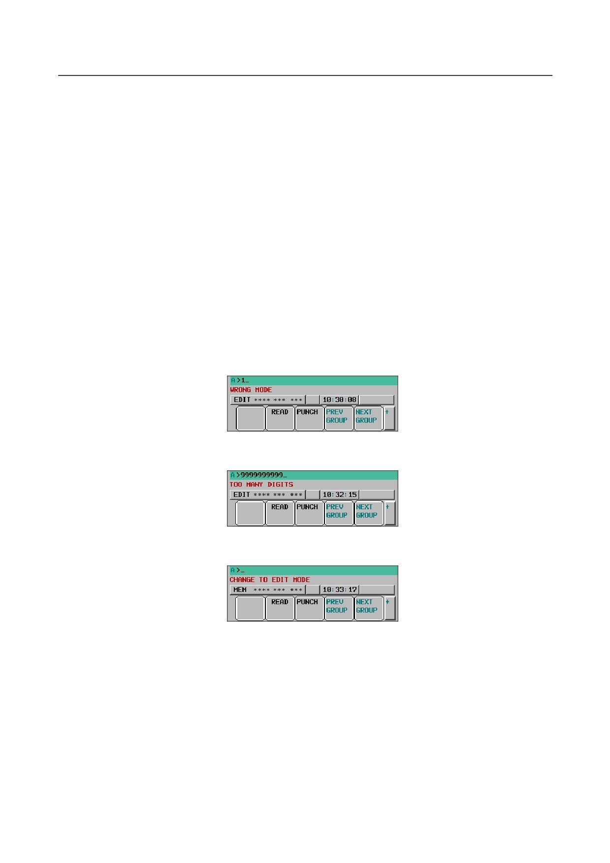
When invalid data is entered (wrong format, value out of range, etc.), when input is disabled (wrong
mode, write disabled, etc.), or when input/output operation is incorrect (wrong mode, etc.), a warning
message is displayed. In this case, the CNC does not accept the setting or input/output operation (retry the
operation according to the message).
Example 1)
When a parameter is entered
Example 2)
When a parameter is entered
Example 3)
When a parameter is output to an external input/output device
(10) Path name
The number of a path whose status is indicated is displayed.
HEAD1 : Indicates that the status being indicated is for path 1.
Other names can be used depending on the settings of parameters 3141 to 3147. The path
name is displayed at the position where (8) is now displayed. When a program is being
edited or operated, (8) is displayed depending on the situation.
- 681 -

12.SETTING AND DISPLAYING DATA OPERATION
B-64304EN/02
12.7 SCREEN ERASURE FUNCTION AND AUTOMATIC
SCREEN ERASURE FUNCTION
Overview
Keeping the same characters displayed in the same positions on the screen for a long time will shorten the
life of the LCD.
To prevent this, the CNC screen can be erased. The screen erasure function allows the user to perform a
key operation to erase the screen. The automatic screen erasure function erases the screen automatically
when there has been no key operation for a parameter-set period of time.
Screen erasure function
When 0 is set in parameter No. 3123, the CNC screen can be erased by pressing the
key and any
function key (such as
or
) at the same time. The CNC screen can be displayed again by
pressing any function key.
Automatic screen erasure function
When there has been no key operation for a time (in minutes) set in parameter No. 3123, the CNC screen
is erased automatically. The CNC screen is displayed again by pressing a key.
-
Screen erasure by the automatic screen erasure function
If the following conditions are all satisfied for the time (in minutes) set in parameter No. 3123, the CNC
screen is erased.
Conditions for automatically erasing the CNC screen
• Parameter No. 3123 ≠ 0
• None of the following key operations is performed.
MDI keys
Soft keys
External key input
• No alarm is issued.
-
Redisplay of the screen by the automatic screen erasure function
If one of the following conditions is satisfied when the CNC screen is off, the CNC screen is displayed
again:
Conditions for redisplaying the CNC screen
• One of the following key operations is performed.
MDI keys
Soft keys
External key input
• An alarm is issued.
-
Screen erasure by using the
key + function key
When a non-zero value is set in parameter No. 3123, the screen is not erased with the
key and a
function key.
-
Set time
Only the time set in parameter No. 3123 for path 1 is valid.
-
Alarm in another path
When an alarm is issued in any of the paths, the screen is not erased.
- 682 -
B-64304EN/02
OPERATION 12.SETTING AND DISPLAYING DATA
Parameter
3123
Time required before a screen saver is activated
[Input type] Setting input
[Data type] Byte path
[Unit of data] min
[Valid data range] 0 to 127
After a time (in minutes) set in parameter No. 3123 passes without key operation, the NC screen is erased
automatically. Pressing a key causes the NC screen to reappear.
NOTE
1 Setting 0 disables automatic screen erasure.
2 This function cannot be used together with manual screen erasure. If 1 or a
larger value is set in this parameter, manual screen erasure is disabled.
12.8 LOAD METER SCREEN
Overview
On the following screens, the servo or spindle load meter and spindle speed meter can be displayed in the
display area of the remaining distance and the display area of modal information.
•
8.4-inch LCD: Program check screen
→ Displaying the spindle load meter and spindle speed meter
T
•
10.4-inch LCD: Screen having current position display on its left half
(Displaying the current position and the program)
→ Switching between the servo load meter and the spindle load meter
12.8.1 For the 8.4-Inch Display Unit
To display the spindle load meter and spindle speed meter on the 8.4-inch display unit, set bit 0 (SMS) of
parameter No. 3117 to 1.
Description
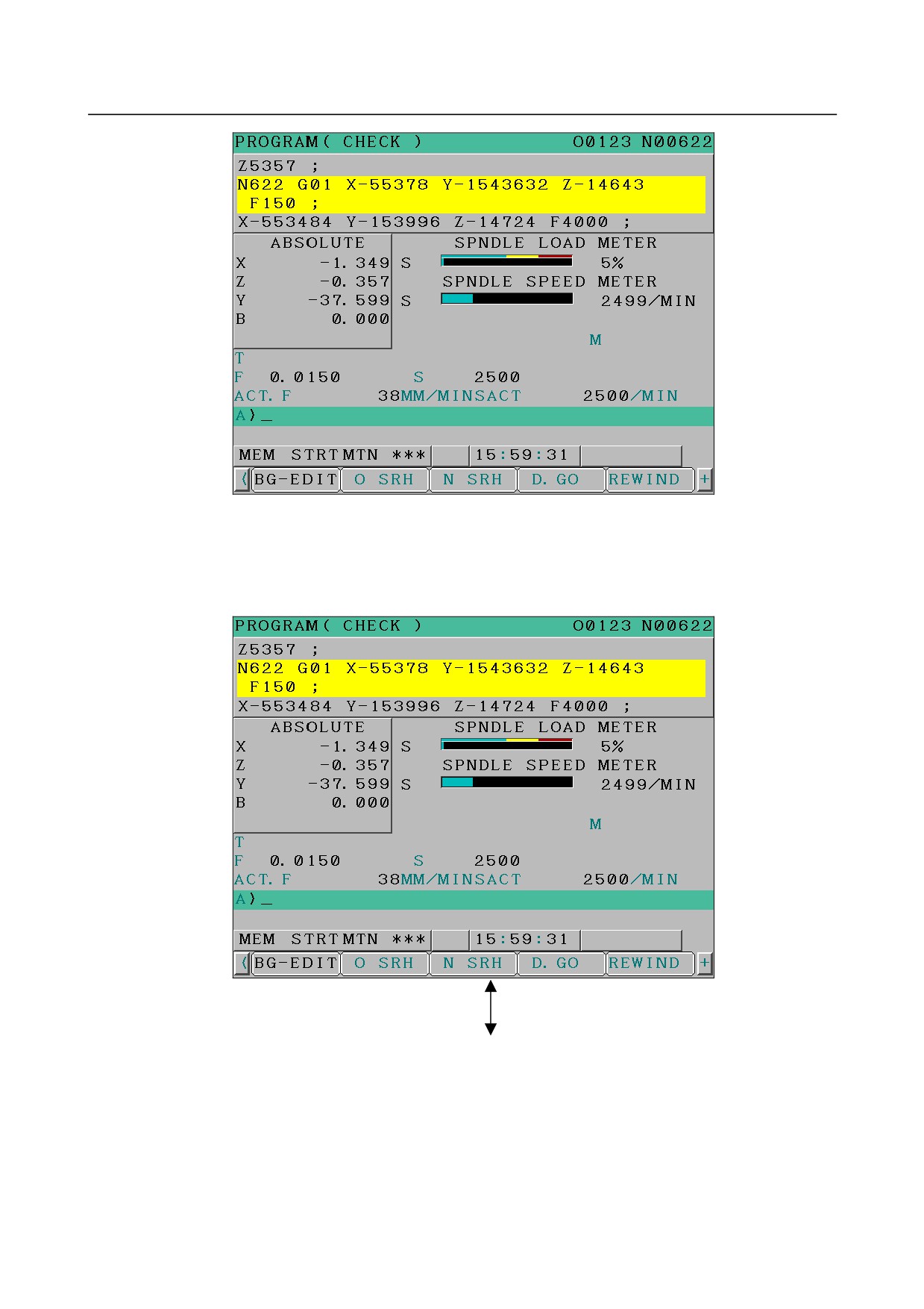
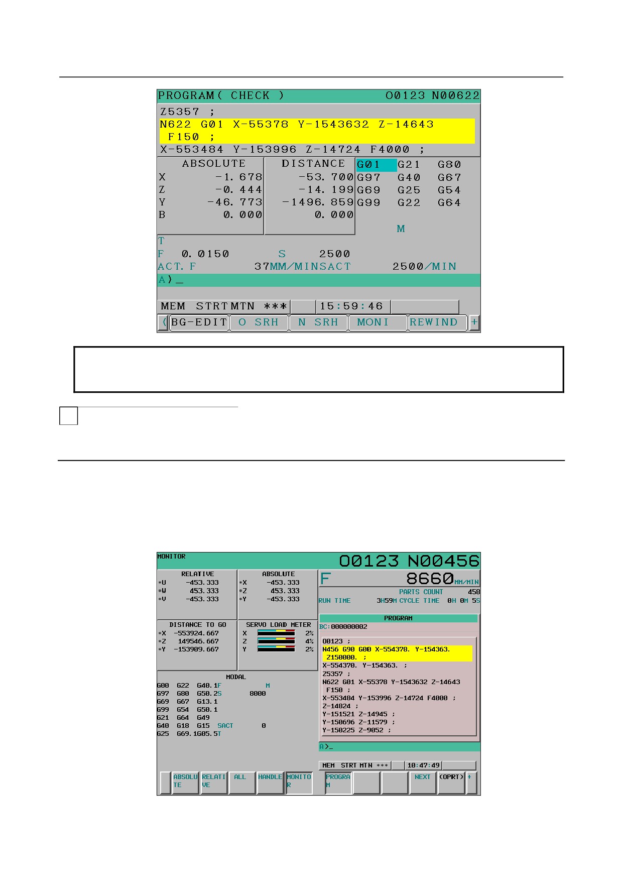
The spindle load meter and spindle speed meter are displayed in the display area of the remaining
distance and modal information on the program check screen.
- 683 -
12.SETTING AND DISPLAYING DATA OPERATION
B-64304EN/02
Fig. 12.8.1.(a) Spindle load meter and spindle speed meter
Switching between screens
To display the spindle load meter and spindle speed meter, press soft key [MONI].
To switch between the remaining distance and modal information, press soft key [D. GO].
Switching with [MONI]/[D. GO]
- 684 -
B-64304EN/02
OPERATION 12.SETTING AND DISPLAYING DATA
NOTE
To use spindle load meter display and spindle speed meter display, the serial
spindle is necessary.
T
12.8.2 For the 10.4-Inch Display Unit
To display the servo load meter and spindle load meter on the screen of the 10.4-inch display unit on the
left half of which the current position is displayed, set bit 7 (PLD) of parameter No. 3192 to 1.
Screen layout
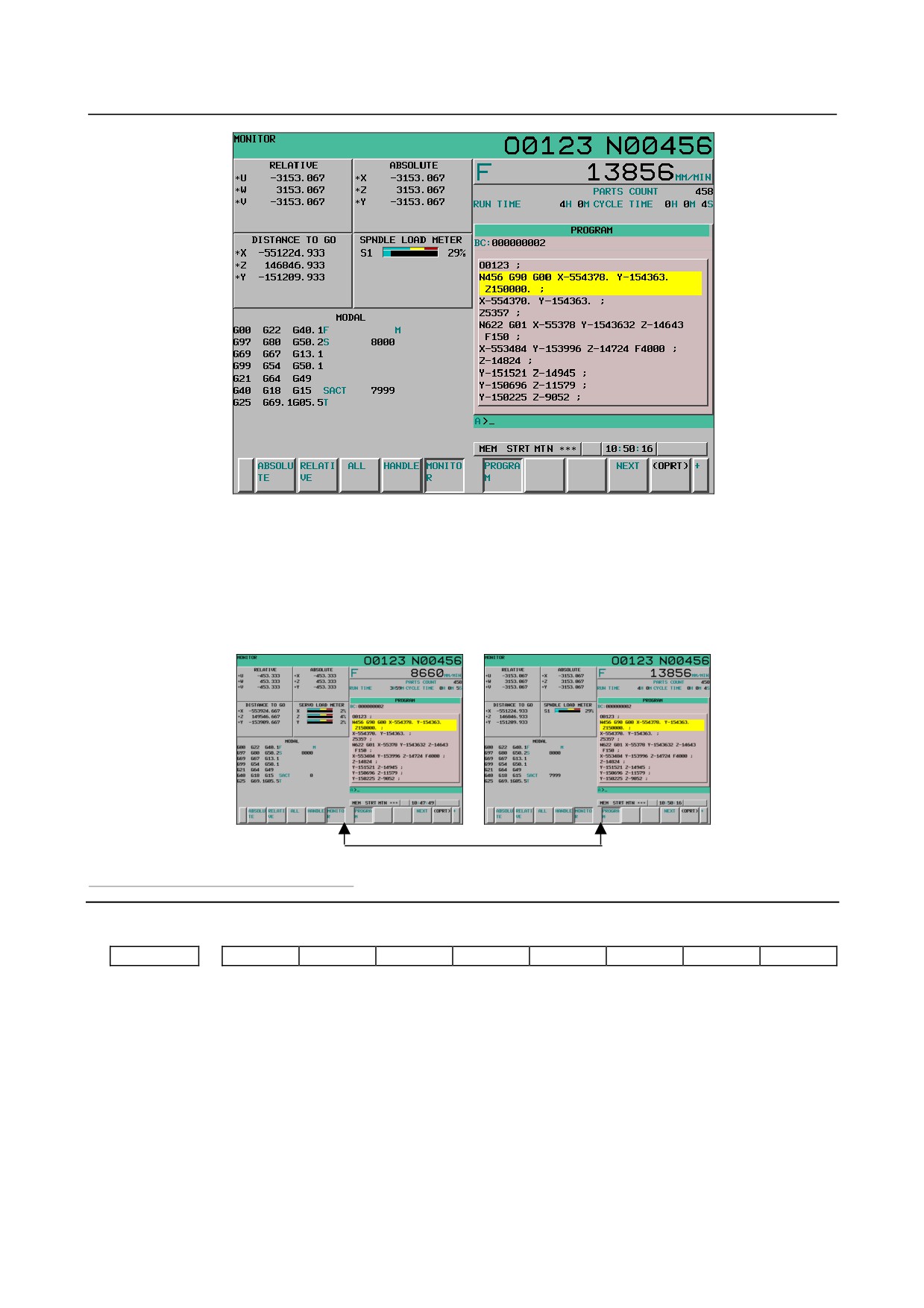
Either the servo load meter or the spindle load meter is displayed in the position of remaining distance
display of all position display.
Fig. 12.8.2.(a) Servo load meter
- 685 -
12.SETTING AND DISPLAYING DATA OPERATION
B-64304EN/02
Fig. 12.8.2 (b) Spindle load meter
Switching between screens
To display the servo load meter or spindle load meter, press soft key [MONITOR] at the bottom of the
screen. The default is the servo load meter. Pressing soft key [MONITOR] switches between the servo
load meter and the spindle load meter.
Servo load meter
Spindle load meter
Press [MONITOR] to switch display.
Parameter
#7
#6
#5
#4
#3
#2
#1
#0
3117
SMS
[Input type] Parameter input
[Data type] Bit path
# 0
SMS On the program check screen of the 8.4-inch display unit, the function for displaying the
spindle load meter and spindle speed meter in the remaining movement amount display
position and modal information display position is:
0: Disabled.
1: Enabled.
- 686 -
B-64304EN/02
OPERATION 12.SETTING AND DISPLAYING DATA
T
#7
#6
#5
#4
#3
#2
#1
#0
3192
PLD
[Input type] Parameter input
[Data type] Bit
# 7
PLD On the screen of the 10.4-inch display unit where positional display is performed on the
left half, the function for displaying the servo axis load meter and spindle load meter is:
0: Disabled.
1: Enabled.
13140
First character in spindle load meter display
13141
Second character in spindle load meter display
[Input type] Setting input
[Data type] Byte spindle
[Valid data range] These parameters set character codes to set the name of each spindle that appears in
spindle load meter display. Any character string consisting of numeric characters,
alphabetical characters, katakana characters, and symbols with a maximum length of two
characters can be displayed as a spindle name.
If 0 is set, the following is displayed:
1st spindle S1
2nd spindle S2
3rd spindle S3
- 687 -
13.GRAPHIC FUNCTION
OPERATION
B-64304EN/02
13 GRAPHIC FUNCTION
Chapter 13, "GRAPHIC FUNCTION", consists of the following sections:
13.1 GRAPHIC DISPLAY
688
13.2 DYNAMIC GRAPHIC DISPLAY (M SERIES)
706
13.3 DYNAMIC GRAPHIC DISPLAY (T SERIES)
744
13.1 GRAPHIC DISPLAY
The graphic display functions enable drawing of the tool path of the program currently used for
machining.
These functions are intended to display the movement of the tool during automatic operation or during
manual operation.
T
In case of a two-path lathe system, the tool paths of two turrets are drawn at the same time in the right and
left views on one screen.
This enables the operator to check the progress of machining and the current tool position.
These functions include the following:
• The current tool position in the workpiece coordinate system is displayed.
• Graphic coordinates can be set freely.
• Rapid traverse and cutting feed can be drawn using a different color for each.
• The values of F, S, and T in the program during drawing are displayed.
• Graphic enlargement or reduction is possible.
13.1.1 Graphic Parameter Screen
Press the function key
(or
when a small MDI unit is used) and then press the [PARAM] soft
key to display the GRAPHIC PARAMETER screen.
On this screen, make necessary settings for drawing of a tool path.
The graphic parameter screen consists of three pages.
- 688 -
B-64304EN/02
OPERATION
13.GRAPHIC FUNCTION
M
-
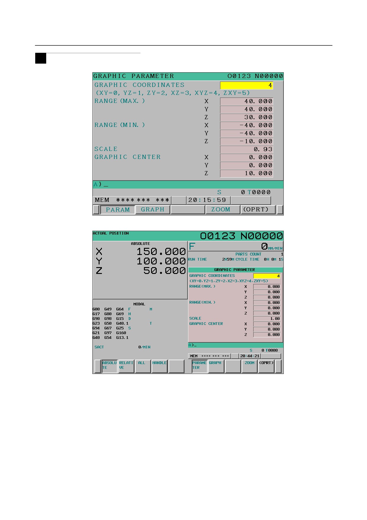
Graphic parameter screen (first page)
Fig. 13.1.1 (a) Graphic parameter screen (first page) (8.4-inch LCD)
Fig. 13.1.1 (b) Graphic parameter screen (first page) (10.4.4-inch LCD)
On graphic parameter screen (first page) , a graphic coordinate system, graphic range, and so forth are set.
In the setting of a graphic coordinate system, the coordinate axes and axis names of the set coordinate
system are displayed. When a three-dimensional coordinate system is displayed, a rotation angle is also
displayed.
The graphic range can be set by one of the two methods: one method by setting the maximum and
minimum values of coordinate positions and the other method by setting the graphic scale factor and
graphic range center.
- 689 -
13.GRAPHIC FUNCTION
OPERATION
B-64304EN/02
-
Graphic parameter screen (second page)
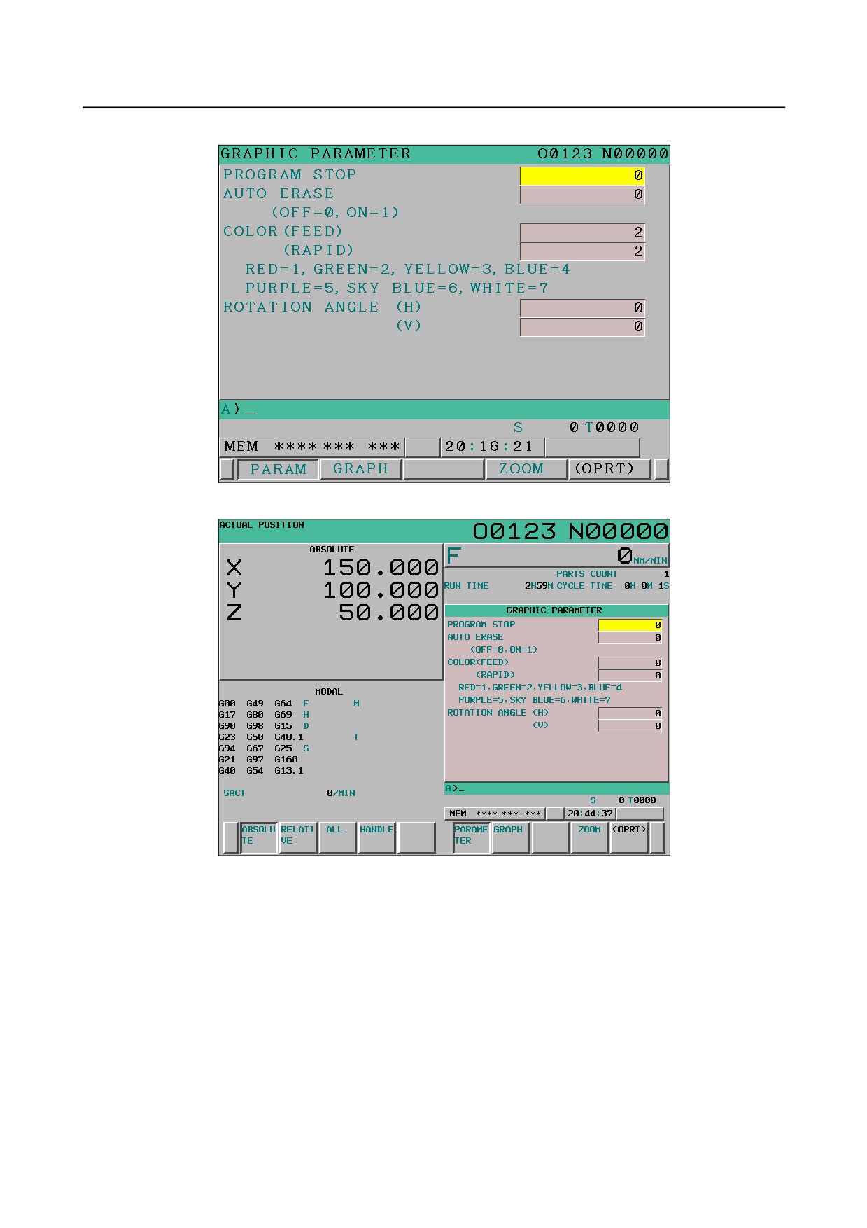
Fig. 13.1.1 (c) Graphic parameter screen (second page) (8.4-inch LCD)
Fig. 13.1.1 (d) Graphic parameter screen (second page) (10..4-inch LCD)
On the graphic parameter screen (second page), a drawing end block, automatic erasure, graphic colors,
and rotation angles are set.
- 690 -
B-64304EN/02
OPERATION
13.GRAPHIC FUNCTION
-
Graphic parameter screen (third page)
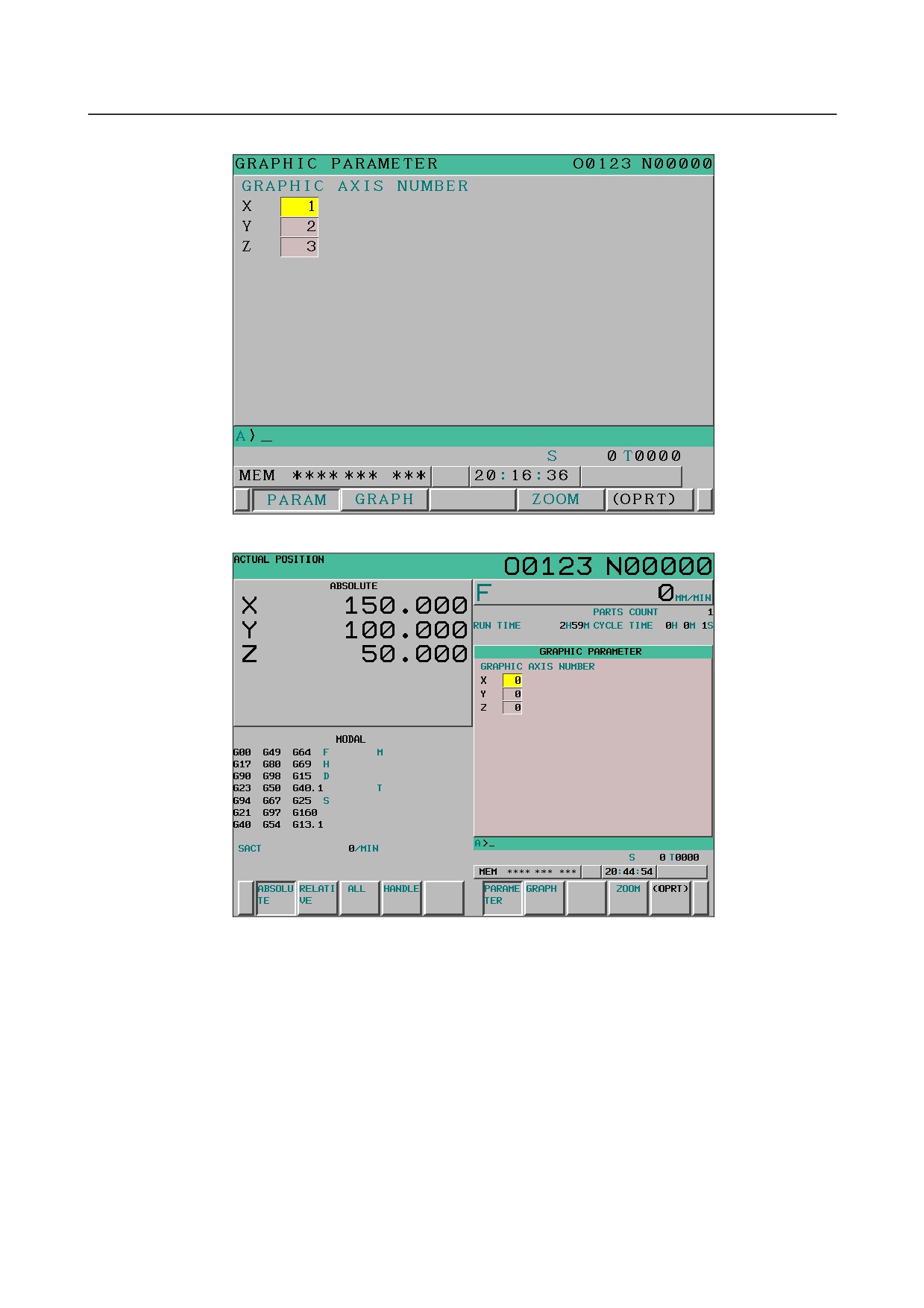
Fig. 13.1.1 (e) Graphic parameter screen (third page) (8.4-inch LCD)
Fig. 13.1.1 (f) Graphic parameter screen (third page) (10.4-inch LCD)
On graphic parameter screen (third page), coordinate axes to be used for drawing are set.
- 691 -
13.GRAPHIC FUNCTION
OPERATION
B-64304EN/02
T
-
Graphic parameter screen (first page)
Fig. 13.1.1 (g) Graphic parameter screen (first page) (8.4-inch LCD)
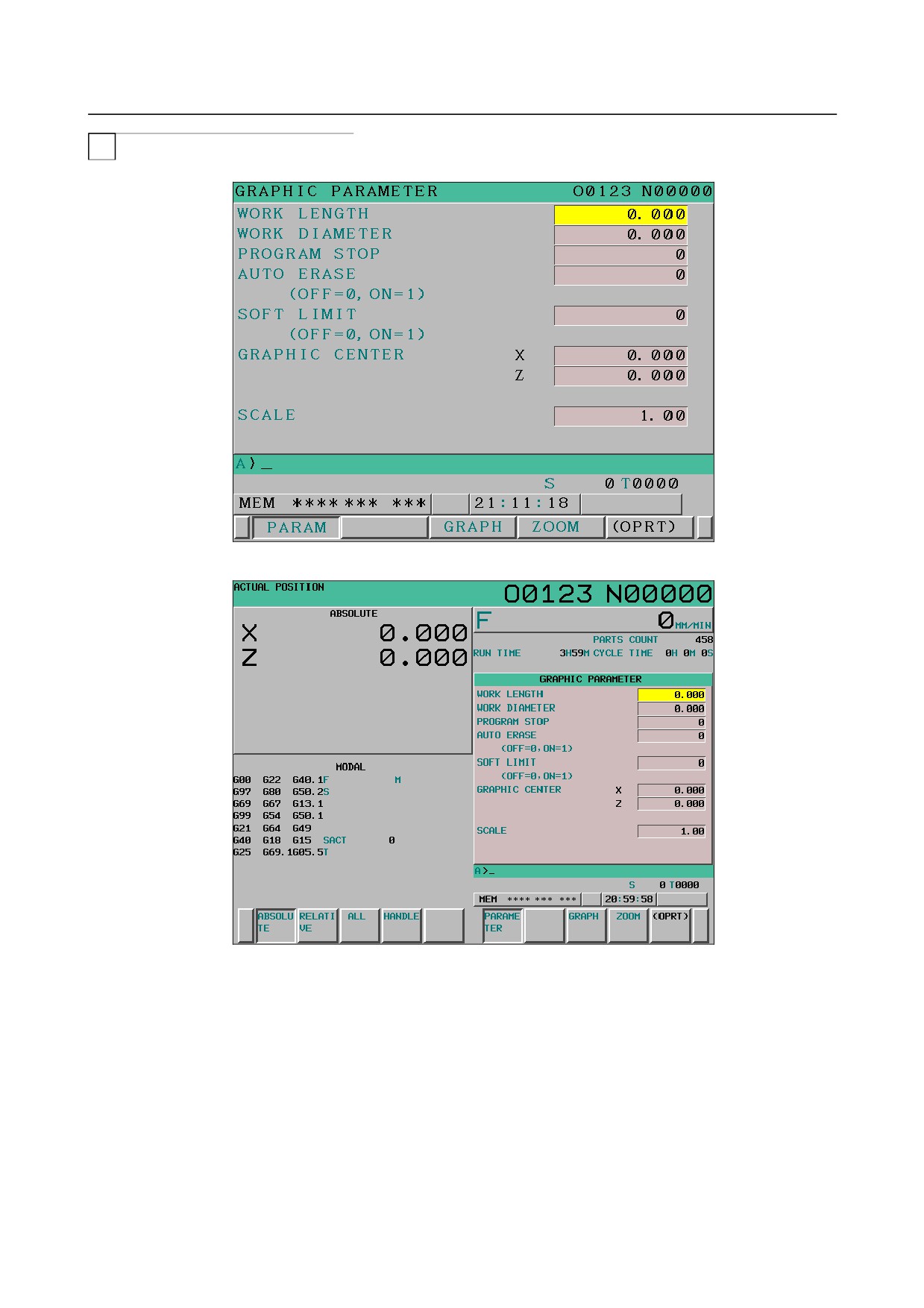
Fig. 13.1.1 (h) Graphic parameter screen (first page) (10.4-inch LCD)
On the graphic parameter screen (first page), blank dimensions (length and diameter), drawing end block,
automatic erasure, soft limit, graphic range, and so forth are set.
The graphic range can be set by one of the two methods: one method by setting the blank dimensions
(length and diameter) and the other method by setting the graphic scale factor and graphic range center.
- 692 -
B-64304EN/02
OPERATION
13.GRAPHIC FUNCTION
-
Graphic parameter screen (second page)
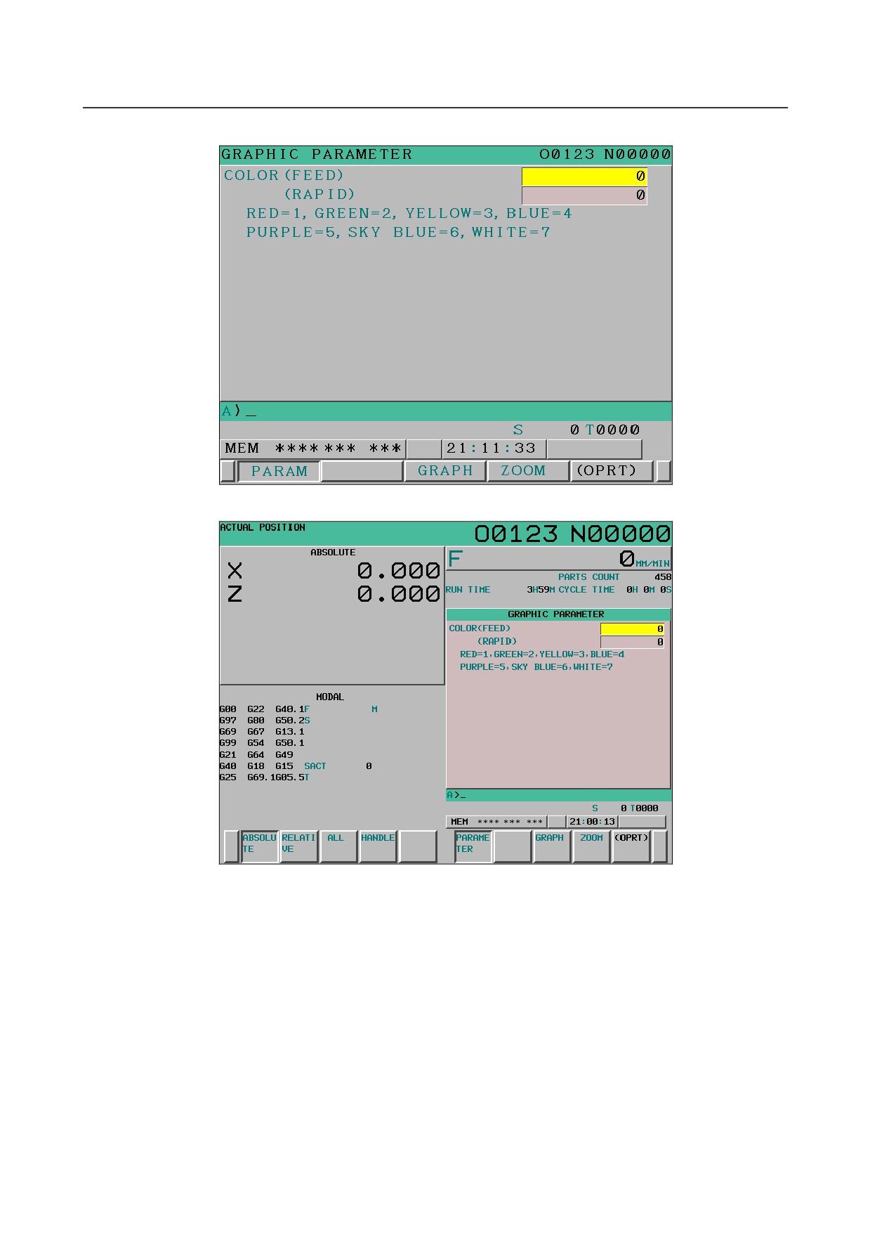
Fig. 13.1.1 (i) Graphic parameter screen (second page) (8.4-inch LCD)
Fig. 13.1.1 (j) Graphic parameter screen (second page) (10.4-inch LCD)
On graphic parameter screen (second page), graphic colors are set.
- 693 -
13.GRAPHIC FUNCTION
OPERATION
B-64304EN/02
-
Graphic parameter screen (third page)
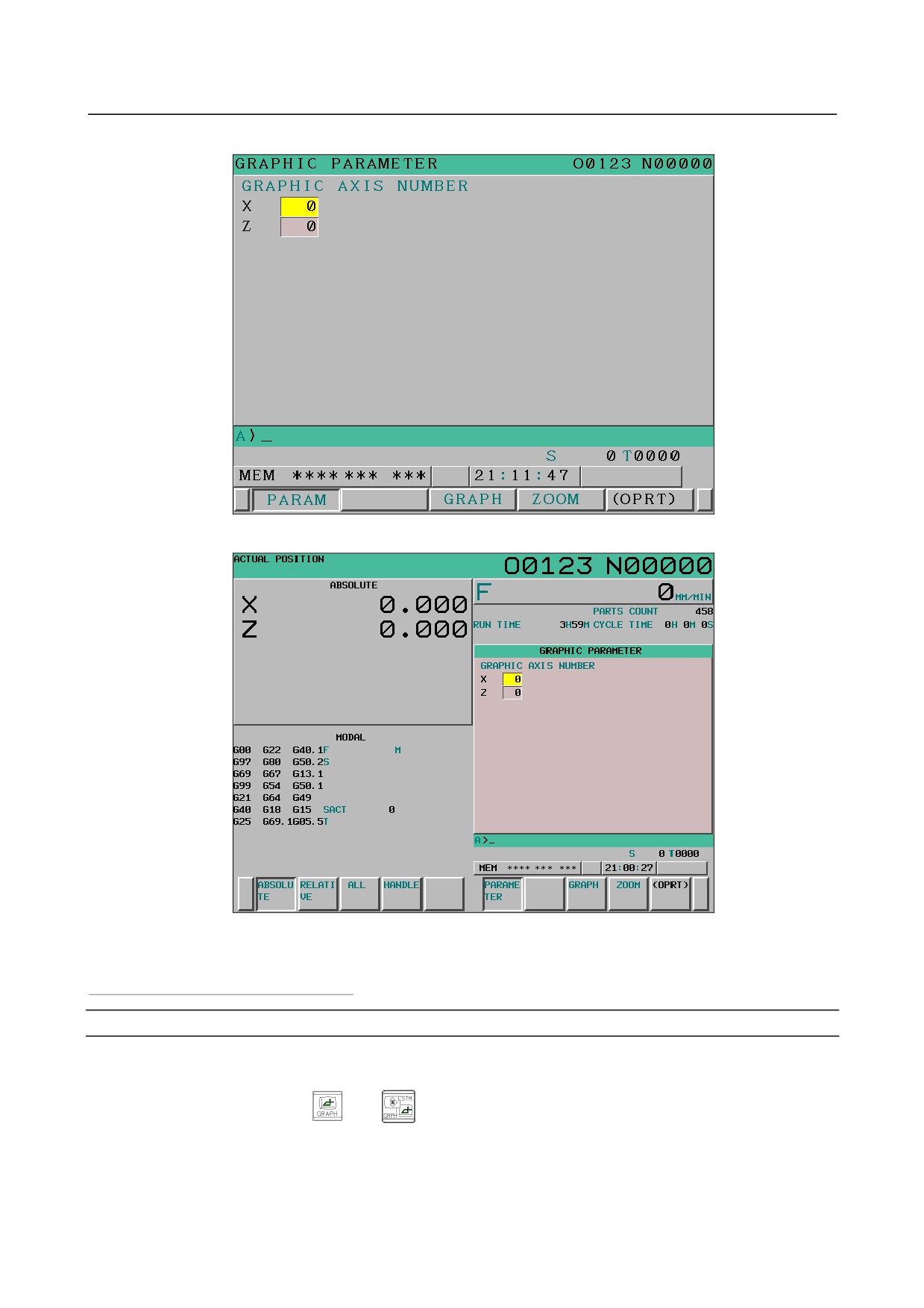
Fig. 13.1.1 (k) Graphic parameter screen (third page) (8.4-inch LCD)
Fig. 13.1.1 (l) Graphic parameter screen (third page) (10.4-inch LCD)
On graphic parameter screen (third page), coordinate axes to be used for drawing are set.
Graphic parameter setting: Operating procedure
Procedure
To display the soft keys for input operations on the graphic parameter screen, do the following:
1
Press the function key
(or
when a small MDI unit is used) to display the GRAPHIC
PARAMETER screen.
2
Press the [(OPRT)] soft key or a numeric key.
- 694 -
B-64304EN/02
OPERATION
13.GRAPHIC FUNCTION
-
Moving the cursor
The cursor can be moved to a desired parameter by the page key
or
and the cursor key
,
,
, or
With the cursor keys, however, you cannot move from page 1 or 2 to page 3.
-
Input of settings (absolute input)
Method 1
(1) Key in a value to be set.
(2) Press the [INPUT] soft key.
Method 2
(1) Key in a value to be set.
(2) Press the
key.
-
Input of settings (incremental input)
Method 1
(1) Key in a value to be incremented to or decremented from the current setting.
(2) Press the [+INPUT] soft key.
Setting standard values
M
After you change the graphic range center and scale factor in a graphic range enlargement/reduction
operation or input operation, you can press the [NORMAL] soft key to restore these values to the settings
obtained by automatic operation based on the maximum and minimum values in the graphic range.
T
After you change the graphic range center and scale factor in a graphic range enlargement/reduction
operation or input operation, you can press the [NORMAL] soft key to restore these values to the settings
obtained by automatic operation based on the blank length and diameter.
Explanation
For tool path drawing, a graphic coordinate system and graphic range need to be set on the graphic
parameter screen.
The graphic parameters to be set on the graphic parameter screen are described below.
If you change any of the graphic parameters and switch to the PATH GRAPHIC screen, the tool path
already drawn is erased.
The graphic parameters are preserved even if the power is turned off.
- 695 -