FANUC Series 0i-MODEL D, Series 0i Mate-MODEL D. OPERATOR'S MANUAL - page 5
8.COORDINATE VALUE AND DIMENSION PROGRAMMING
B-64304EN/02
NOTE
1
A specified value less than the least increment is treated as shown below
(rounded off to the right side).
Example 1)
When a value is specified directly at an address (in the case of IS-B)
X-0.0004 ;
Treated as X0.000
X0.0004 ;
Treated as X0.000
X-0.0005 ;
Treated as X0.000
X0.0005 ;
Treated as X0.001
X-0.0006 ;
Treated as X-0.001
X0.0006 ;
Treated as X0.001
As shown in the table below, commands including positive and negative
fractions having the same absolute value with respect to zero are repeated.
In right side rounding, the results are periodical. In general rounding,
however, the results are not periodical due to rounding symmetry with respect
to zero.
To prevent this, right side rounding is used for calculation.
Right side rounding
General rounding
G90 G00 X0 ;
X 0.000
X 0.000
G91 X-0.0015 ;
X -0.001
X -0.002
G91 X0.0015 ;
X 0.000
X -0.001
G91 X-0.0015 ;
X -0.001
X -0.003
G91 X0.0015 ;
X 0.000
X -0.002
G91 X-0.0015 ;
X -0.001
X -0.004
G91 X0.0015 ;
X 0.000
X -0.003
Example 2)
When a value is assigned to a macro variable (in the case of IS-B)
Similarly, right side rounding is performed.
#100=1.2345 ;
X#100 ;
Treated as X1.235
#100=-1.2345 ;
X#100 ;
Treated as X-1.234
2
When more than nine digits are specified, an alarm occurs. If a value is entered
with a decimal point, the number of digits is also checked after the value is
converted to an integer according to the least input increment.
Examples:
X0.123456789 ;
Alarm PS0003 occurs because more than nine digits are specified.
X1234567.8 ;
If the least input increment is 0.001 mm, the value is converted to integer
1234567800. Because the integer has more than nine digits, an alarm
occurs.
- 96 -
B-64304EN/02
PROGRAMMING
8.COORDINATE VALUE AND DIMENSION
8.4
DIAMETER AND RADIUS PROGRAMMING
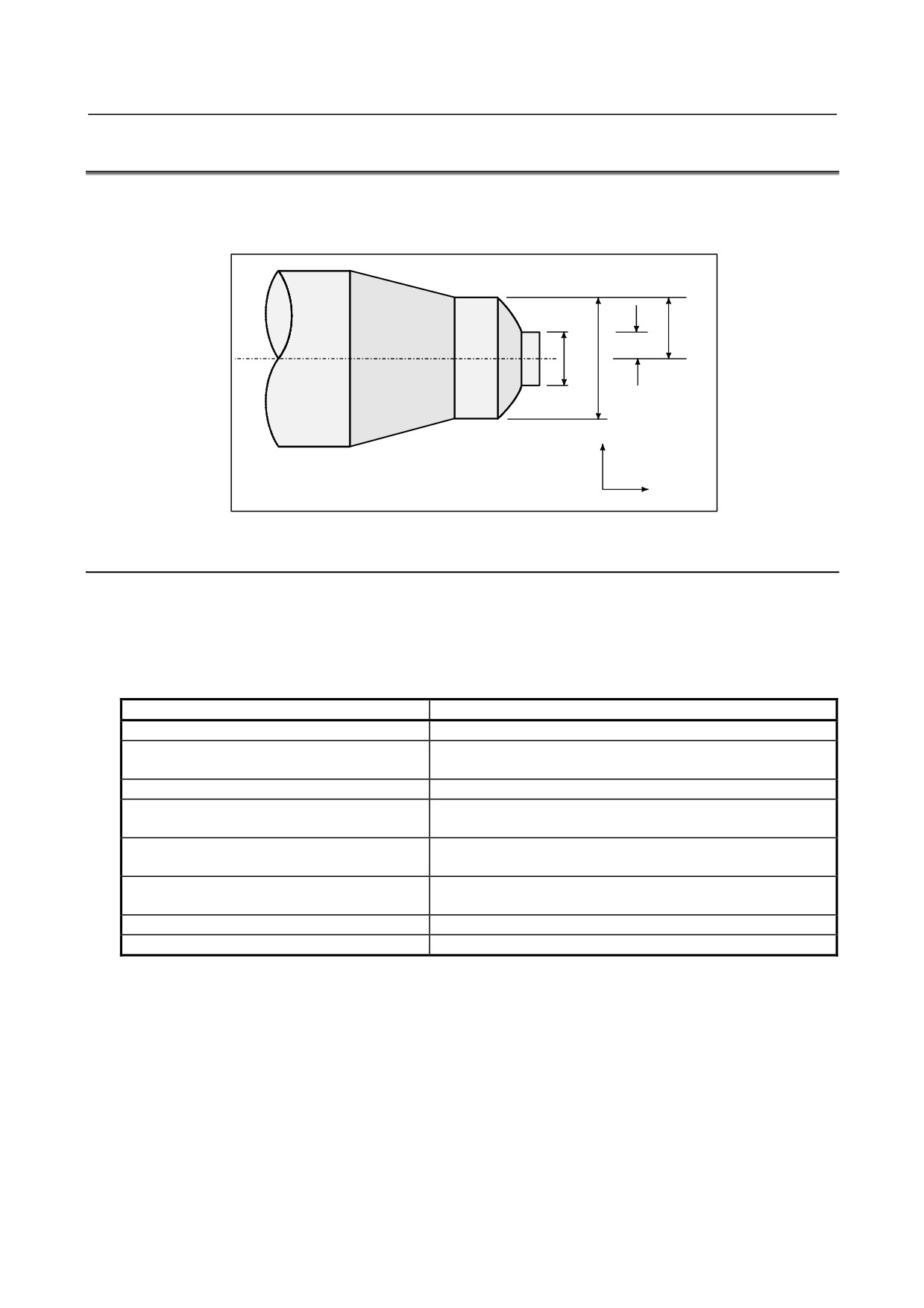
Since the workpiece cross section is usually circular in CNC lathe control programming, its dimensions
can be specified in two ways :
Diameter and Radius
A
B
R2
R1
D1
D2
X axis
D1, D2 : Diameter programming
R1, R2 : Radius programming
Z axis
When the diameter is specified, it is called diameter programming and when the radius is specified, it is
called radius programming.
Explanation
-
Notes on diameter programming/radius programming for each command
Radius programming or diameter programming can be specified by bit 3 (DIA) of parameter No.1006.
When using diameter programming, note the conditions listed in the Table 8.4 (a).
Table 8.4 (a) Notes on specifying diameter value
Item
Notes
X axis command
Specified with a diameter value
Specified with a diameter value
Incremental command
In the above figure, specifies D2 minus D1 for tool path B to A.
Coordinate system setting
Specifies a coordinate value with a diameter value
Bit 1 of parameter No.5004 determines either diameter or
Component of tool offset value
radius value
Parameters in canned cycle (T series), such as
Specifies a radius value
cutting depth along X axis. (R)
Radius designation in circular interpolation (R,
Specifies a radius value
I, K, and etc.)
Feedrate along axis
Specifies change of radius/rev. or change of radius/min.
Display of axis position
Displayed as diameter value
- 97 -

9. SPINDLE SPEED FUNCTION
(S FUNCTION)
PROGRAMMING
B-64304EN/02
9 SPINDLE SPEED FUNCTION
(S FUNCTION)
The spindle speed can be controlled by specifying a value following address S.
Chapter 9, "SPINDLE SPEED FUNCTION (S FUNCTION)", consists of the following sections:
9.1 SPECIFYING THE SPINDLE SPEED WITH A CODE
98
9.2 SPECIFYING THE SPINDLE SPEED VALUE DIRECTLY (S5-DIGIT COMMAND)
98
9.3 CONSTANT SURFACE SPEED CONTROL (G96, G97)
98
9.4 SPINDLE POSITIONING FUNCTION
102
9.5 SPINDLE SPEED FLUCTUATION DETECTION
107
9.6 SPINDLE CONTROL WITH SERVO MOTOR
110
9.1
SPECIFYING THE SPINDLE SPEED WITH A CODE
When a value is specified after address S, the code signal and strobe signal are sent to the machine to
control the spindle rotation speed.
A block can contain only one S code. Refer to the appropriate manual provided by the machine tool
builder for details such as the number of digits in an S code or the execution order when a move
command and an S code command are in the same block.
9.2
SPECIFYING THE SPINDLE SPEED VALUE DIRECTLY
(S5-DIGIT COMMAND)
The spindle speed can be specified directly by address S followed by a max. five-digit value (min-1). The
unit for specifying the spindle speed may vary depending on the machine tool builder. Refer to the
appropriate manual provided by the machine tool builder for details.
9.3
CONSTANT SURFACE SPEED CONTROL (G96, G97)
Specify the surface speed (relative speed between the tool and workpiece) following S. The spindle is
rotated so that the surface speed is constant regardless of the position of the tool.
Format
-
Constant surface speed control command
G96 Sxxxxx ;
↑ Surface speed (m/min or feet/min)
This surface speed unit may change according to machine tool builder's specification.
-
Constant surface speed control cancel command
G97 Sxxxxx ;
↑ Spindle speed (min-1)
This surface speed unit may change according to machine tool builder's specification.
- 98 -

9.SPINDLE SPEED FUNCTION
B-64304EN/02
PROGRAMMING
(S FUNCTION)
-
Constant surface speed controlled axis command
G96 Pα ;
P0 : Axis set in the parameter (No. 3770)
P1 : X axis, P2 : Y axis, P3 : Z axis, P4 : 4th axis
P5 : 5th axis
T
NOTE
If multi-spindle control (spindle selecting based on address P) is enabled, axis
specification based on address P is disabled. Use parameter No. 3770 for axis
specification.
-
Clamp of maximum spindle speed
G92 S_ ;
The maximum spindle speed (min-1) follows S.
T
G50 S_ ;
The maximum spindle speed (min-1) follows S.
NOTE
G50 can be used with G code system A.
Explanation
-
Constant surface speed control command (G96)
G96 (constant surface speed control command) is a modal G code. After a G96 command is specified,
the program enters the constant surface speed control mode (G96 mode) and specified S values are
assumed as a surface speed. A G96 command must specify the axis along which constant surface speed
control is applied. A G97 command cancels the G96 mode. When constant surface speed control is
applied, a spindle speed higher than the value specified in G92 S_ ; or G50 S_ ; (maximum spindle speed)
is clamped at the maximum spindle speed. When the power is turned on, the maximum spindle speed is
not yet set and the speed is not clamped. S (surface speed) commands in the G96 mode are assumed as S
= 0 (the surface speed is 0) until M03 (rotating the spindle in the positive direction) or M04 (rotating the
spindle in the negative direction) appears in the program.
- 99 -
9. SPINDLE SPEED FUNCTION
(S FUNCTION)
PROGRAMMING
B-64304EN/02
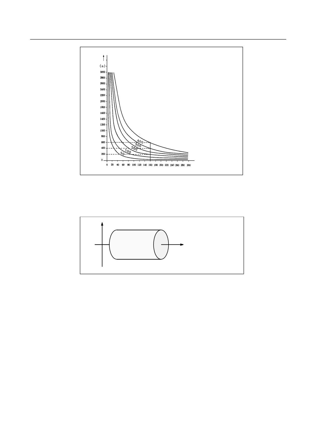
Spindle speed (min-1)
The spindle speed (min-1) almost coincides
with the surface speed (m/min) at approx.
160 mm (radius).
Surface speed S is 600 m/min.
Relation between workpiece radius,
Radius (mm)
spindle speed and surface speed
Fig. 9.3 (a) Relation between workpiece radius, spindle speed and surface speed
-
Setting the workpiece coordinate system for constant surface speed control
To execute the constant surface speed control, it is necessary to set the workpiece coordinate system , and
so the coordinate value at the center of the rotary axis, for example, Z axis, (axis to which the constant
surface speed control applies) becomes zero.
X
Z
0
Fig. 9.3 (b) Example of the workpiece coordinate system for constant surface speed control
- 100 -
9.SPINDLE SPEED FUNCTION
B-64304EN/02
PROGRAMMING
(S FUNCTION)
-
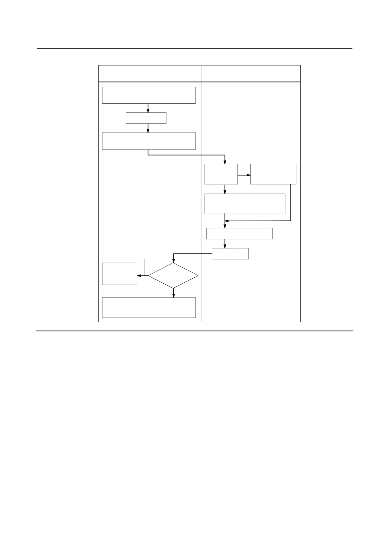
Surface speed specified in the G96 mode
G96 mode
G97 mode
Specify the surface speed in m/min
(or feet/min)
G97 command
Store the surface speed in m/min
(or feet/min)
Specified
Command for
The specified
the spindle
spindle speed
speed
(min-1) is used
Not specified
The surface speed (m/min or
feet/min) is converted to the
spindle speed (min-1)
Commands other than G96
G96 command
Specified
The specified
Command
surface
for the surface
speed is used
speed
Not specified
The stored surface speed (m/min or
feet/min) is used. If no surface
is stored, 0 is assumed.
Limitation
-
Constant surface speed control for threading
The constant surface speed control is also effective during threading. Accordingly, it is recommended
that the constant surface speed control be invalidated with G97 command before starting the scroll
threading and taper threading, because the response problem in the servo system may not be considered
when the spindle speed changes.
-
Constant surface speed control for rapid traverse (G00)
In a rapid traverse block specified by G00, the constant surface speed control is not made by calculating
the surface speed to a transient change of the tool position, but is made by calculating the surface speed
based on the position at the end point of the rapid traverse block, on the condition that cutting is not
executed at rapid traverse.
- 101 -
9. SPINDLE SPEED FUNCTION
(S FUNCTION)
PROGRAMMING
B-64304EN/02
Example
T
Radius value
Programmed path
X
Tool path after offset
1
2
700
4
675
600
N11
N16
3
500
N15
N11
N14
400
N16
N15
375
300
N14
200
φ600
φ400
100
Z
300 400 500 600
700 800 900
1000
1100
1300 14001500
1200
1475
1050
N8 G00 X1000.0 Z1400.0 ;
N9 T33;
N11 X400.0 Z1050.0 ;
N12 G50 S3000 ; (Designation of max. spindle speed)
N13 G96 S200 ; (Surface speed 200 m/min)
N14 G01 Z700.0 F1000 ;
N15 X600.0 Z 400.0;
N16 Z_ ;
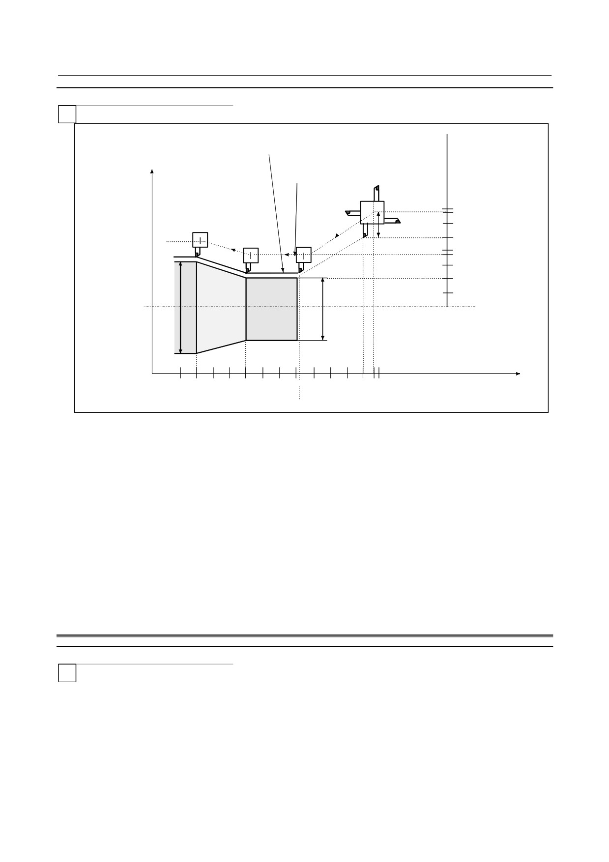
The CNC calculates the spindle speed which is proportional to the specified surface speed at the position
of the programmed coordinate value on the X axis. This is not the value calculated according to the X
axis coordinate after offset when offset is valid. At the end point N15 in the example above, the speed at
600 dia. (Which is not the turret center but the tool nose) is 200 m/min. If X axis coordinate value is
negative, the CNC uses the absolute value.
9.4
SPINDLE POSITIONING FUNCTION
Overview
T
In turning, the spindle connected to the spindle motor is rotated at a certain speed to rotate the workpiece
mounted on the spindle. This spindle control status is referred to as spindle rotation mode.
The spindle positioning function turns the spindle connected to the spindle motor by a certain angle to
position the workpiece mounted on the spindle at a certain angle. This spindle control status is referred
to as spindle positioning mode.
The spindle positioning function involves the following three operations:
1.
Canceling the spindle rotation mode and entering the spindle positioning mode
- 102 -

9.SPINDLE SPEED FUNCTION
B-64304EN/02
PROGRAMMING
(S FUNCTION)
Place the spindle in the spindle positioning mode and establish a reference position by specifying a
given M code (set with a parameter).
(Spindle orientation)
2.
Positioning the spindle in the spindle positioning mode
The spindle is positioned in either of the two methods:
1)
Positioning with an arbitrary angle by an axis address
2)
Positioning with a semi-fixed angle by a given M code (set with a parameter)
3.
Canceling the spindle positioning mode, and entering the spindle rotation mode
Place the spindle in the spindle rotation mode by specifying a given M code (set with a parameter).
The least command increment, least input increment, and maximum value for the spindle positioning axis
are as follows:
• Least command increment
360
4096 ••0.088 deg (when the gear ratio of the spindle to the position coder
• Least input increment
0.001 deg (IS-B)
• Maximum value
±999999.999 deg
NOTE
1 Be sure to set 1 in bit 1 (AXC) of parameter No.8133 and 0 in bit 2 (SCS) of
parameter No.8133 to use the spindle positioning function.
2 Both serial spindle Cs contour control function and spindle positioning function
cannot be made effective at the same time.
If both are specified as AXC=1 and SCS=1, both functions become invalid.
Therefore, when a negative value is set in parameter No.1023 with above
specification, alarm (SV1026) is generated.
3 Be sure to set 0 in bit 1 (AXC) of parameter No.8133 and 1 in bit 2 (SCS) of
parameter No.8133 to use the serial spindle Cs contour control function.
9.4.1
Spindle Orientation
When spindle positioning is first performed after the spindle motor is used for normal spindle operation,
or when spindle positioning is interrupted, the spindle orientation is required.
Orientation permits the spindle to stop at a predetermined position.
Orientation is directed by the M code set in parameter No. 4960. The direction of orientation can be set
with a parameter.
For the serial spindle, it is set in bit 4 (RETSV) of parameter No. 4000. With the grid shift function, the
orientation position can be shifted in a range of 0 to 360 deg with parameter No. 4073 for a serial spindle.
-
Feedrate during spindle orientation
An orientation feedrate for a serial spindle is determined by a spindle parameter setting.
In orientation, the serial spindle stops at the orientation position after several rotations of the spindle
motor.
-
Omission of orientation
By using bit 2 (ISZ) of parameter No. 4950, orientation upon switching to spindle positioning mode can
be omitted if it is unnecessary
(for example, when no start position is specified and incremental
positioning from the current position is only required). More specifically, when an M code for
switching to spindle positioning mode is specified, the spindle control mode is simply switched to spindle
positioning mode and then the processing is completed without orientation.
- 103 -
9. SPINDLE SPEED FUNCTION
(S FUNCTION)
PROGRAMMING
B-64304EN/02
-
Program reference position
The position at which orientation is completed is assumed to be a program reference position. However,
the program reference position can be changed through coordinate system setting (G92 or G50) or
automatic coordinate system setting (bit 0 (ZPR) of parameter No. 1201).
When a setting is made to omit orientation, a program reference position is not established, and operation
by an absolute command is unpredictable during spindle positioning with an axis address.
9.4.2
Spindle Positioning (T Series)
T
The spindle can be positioned with a semi-fixed angle or arbitrary angle.
-
Positioning with a semi-fixed angle
Use an M code to specify a positioning angle. The specifiable M code value may be one of the six
values from Mα to M (α+5). Value α must be set in parameter No. 4962 beforehand. The positioning
angles corresponding to Mα to M (α+5) are listed below. Value β must be set in parameter No. 4963
beforehand.
M-code
Positioning angle
(Ex.) β = 30°
(Ex.) β = α + 5
Mα
β
30°
M (α + 1)
2β
60°
M (α + 2)
3β
90°
M (α + 3)
4β
120°
M (α + 4)
5β
150°
M (α + 5)
6β
180°
When the number of M codes to be used, value γ, is specified in parameter No. 4964, a specifiable M
code value may be in a range of values from Mα to M (α + (γ - 1)), up to 255 values from Mα to M (α +
(255 - 1)).
M code
Positioning angle
(Ex.) β = 30°
(Ex.) γ = 11
Mα
β
30°
M (α + 1)
2β
60°
M (α + 2)
3β
90°
M (α + 3)
4β
120°
M (α + 11 - 1)
11β
330°
The direction of rotation can be specified in IDM (bit 1 of parameter 4950).
-
Positioning with an arbitrary angle
Specify the position with an arbitrary angle using the axis address followed by a signed numeric value or
numeric values. The axis address must be specified in the G00 mode.
(The explanation below is given assuming that a C axis address is set.)
(Example)
C-45000
C180.000
A numeric with the decimal point can be entered. The value must be specified in degrees.
(Example)
C36.0=C36 degrees
-
Absolute commands and incremental commands
Incremental commands are always used for positioning with a semi-fixed angle (using M codes).
- 104 -
9.SPINDLE SPEED FUNCTION
B-64304EN/02
PROGRAMMING
(S FUNCTION)
The direction of rotation can be specified with bit 1 (IDM) of parameter No. 4950.
Absolute and incremental commands can be used for positioning with an arbitrary angle.
With absolute commands for positioning with an arbitrary angle, when the rotation axis rollover function
is used (bit 0 (ROA) of parameter No. 1008 is 1), shortcut control is also enabled (bit 1 (RAB) of
parameter No. 1008 is 0).
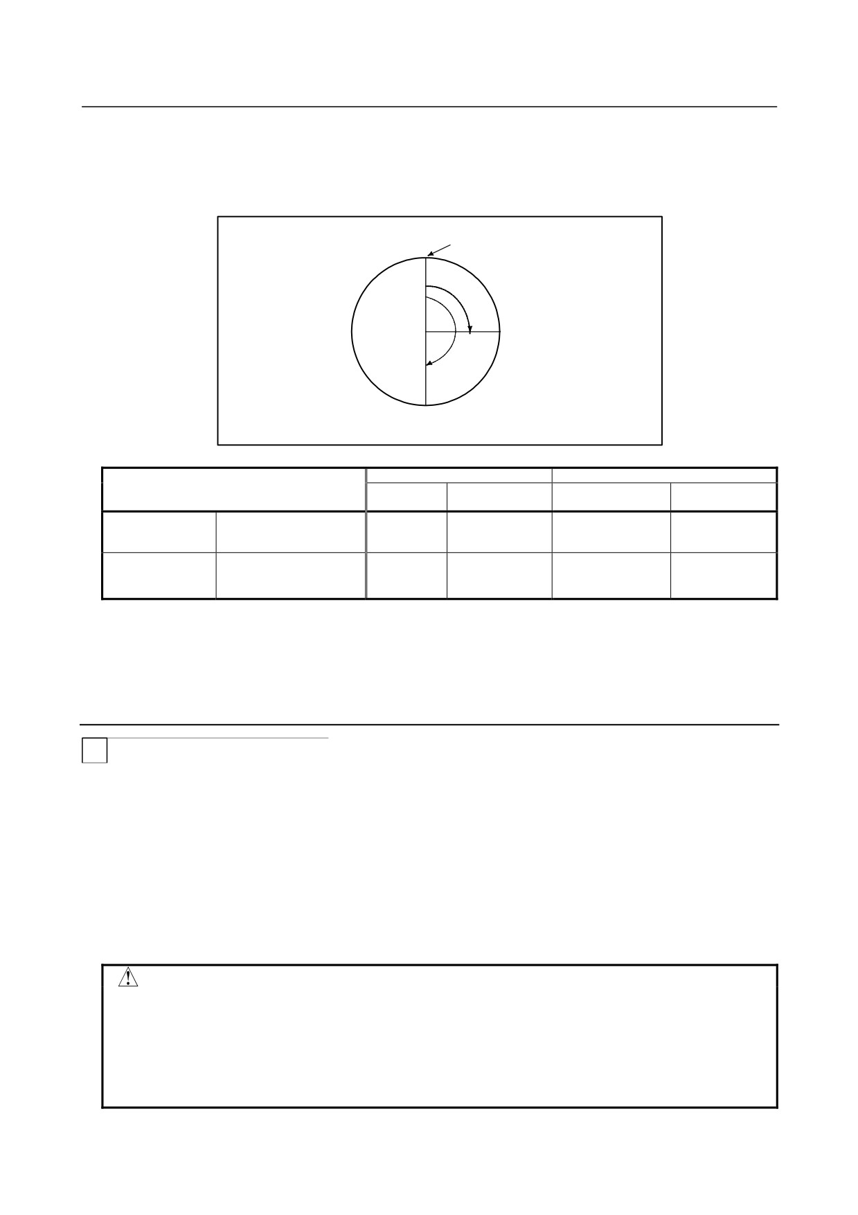
Program reference position
90°
A
180°
B
G-code system A
G-code system B or C
Command format
Address
Command A-B in
Address used and G
Command A-B in
used
the above figure
code
the above figure
Specify the end point with a
Absolute command
distance from the program
C
C180. ;
G90,C
G90 C180. ;
reference position.
Specify a distance from
Incremental
the start point to the end
H
H90. ;
G91,C
G91 C90. ;
command
point.
-
Feedrate during positioning
The feedrate during positioning equals the rapid traverse speed specified in parameter No. 1420.
For the specified speed, an override of 100%, 50%, 25%, and F0 (parameter No. 1421) can be applied.
9.4.3
Canceling Spindle Positioning (T Series)
T
When modes are to be switched from spindle positioning to normal spindle rotation, the M code set in
parameter No. 4961 must be specified.
Also, the spindle positioning mode is canceled and the spindle rotation mode is set in the following cases:
<1> A reset operation (including an emergency stop) occurs when a servo alarm is issued.
<2> A reset operation (including an emergency stop) occurs when a spindle alarm is issued.
<3> An orientation operation in progress is stopped due to a reset or alarm, or for some other reason.
<4> A reset operation (including an emergency stop) occurs when bit (IOR) 0 of parameter No. 4950 is
1.
CAUTION
1 During execution of spindle positioning sequences (canceling the spindle rotation
mode and entering the spindle positioning mode, positioning the spindle in the
spindle positioning mode, and canceling the spindle positioning mode and
entering the spindle rotation mode), the automatic operation stop signal *SP is
invalid. This means that automatic operation does not stop until all the
sequences are completed, even when the *SP signal becomes 0.
- 105 -
9. SPINDLE SPEED FUNCTION
(S FUNCTION)
PROGRAMMING
B-64304EN/02
CAUTION
2 Dry run and machine lock cannot be performed during spindle positioning.
3 Auxiliary function lock is disabled for M codes for the spindle positioning function.
4 Both serial spindle Cs contour control function (bit 2 (SCS) of parameter
No.8133) and spindle positioning function (bit 1 (AXC) of parameter No. 8133)
cannot be made effective at the same time.
If both are specified as AXC=1 and SCS=1, both functions become invalid.
Therefore, when a negative value is set in parameter No.1023 with above
specification, alarm (SV1026) is generated.
Be sure to set AXC=1 and SCS=0 to use the spindle positioning function.
Be sure to set AXC=0 and SCS=1 to use the serial spindle Cs contour control
function.
5 The spindle positioning axis is handled as a controlled axis. Therefore,
controlled axis-related signals (such as the overtravel signal) must be set.
6 When the rigid tapping function (bit 3 (NRG) of parameter No. 8135 ) is used
together with the spindle positioning function (bit 1 (AXC) of parameter No.
8133), rigid tapping cannot be specified in the spindle positioning mode or
spindle positioning cannot be specified in the rigid tapping mode.
NOTE
1 M code commands for positioning of a spindle must be specified in a single
block. Other commands must not be contained in the same block. (Also, M code
commands for positioning of another spindle must not be contained in the same
block.)
Even when the single-block, multiple-M code command function is also used,
related M codes must be specified in a single block.
2 Even when the single-block, multiple-M code command function is also used,
related M codes must be specified in a single block.
3 Axis address commands for positioning of a spindle must be specified in a single
block. Other commands must not be contained in the same block. However, the
following commands can be contained in the same block where axis address
commands are specified:
G00, G90, G91, G92 (G-code systems B and C)
G00, G50 (G-code system A)
4 M code commands for spindle positioning specify M codes that are not buffered.
5 Spindle positioning cannot be performed by manual operation (in jog feed,
manual handle feed, or other mode).
6 Spindle positioning cannot be performed by PMC axis control.
7 For spindle positioning, program restart operation cannot be performed. Use
the MDI for these operations.
8 The stored stroke limit check is disabled for the spindle positioning axis.
9 The control axis detach function is disabled for the spindle positioning axis.
10 The pitch error compensation function is disabled for the spindle positioning axis.
11 When a setting is made to omit spindle orientation, the reference position return
completion signal does not become 1.
12 In spindle orientation, all-axis interlock and axis-specific interlock are checked
only when a block is started. A signal is ignored if input during the execution of
the block.
13 A difference between a specified travel distance and an actual travel distance is
maintained until spindle positioning mode is canceled.
- 106 -

9.SPINDLE SPEED FUNCTION
B-64304EN/02
PROGRAMMING
(S FUNCTION)
9.5
SPINDLE SPEED FLUCTUATION DETECTION (T SERIES)
T
Overview
With this function, an overheat alarm (OH0704) is raised and the spindle speed fluctuation detection
alarm signal SPAL is issued when the spindle speed deviates from the specified speed due to machine
conditions.
This function is useful, for example, for preventing the seizure of the guide bushing.
G26 enables spindle speed fluctuation detection.
G25 disables spindle speed fluctuation detection.
Format
-
Spindle fluctuation detection on
G26 Pp Qq Rr Ii;
P: Time (in ms) from the issue of a new spindle rotation command (S command) to the start
of checking whether the actual spindle speed is so fast that an overheat can occur.
When a specified speed is reached within the time period of P, a check is started at that
time.
Q: Tolerance (%) of a specified spindle speed
actual spindle speed
q
=1−
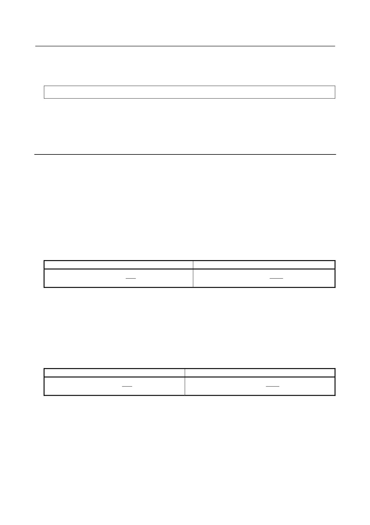
×
100
specified spndle speed
If a specified spindle speed lies within this range, it is regarded as having reached the
specified value. Then, the checking of an actual spindle speed is started.
R: Spindle speed fluctuation (%) at which the actual spindle speed is so fast that an
overheat can occur
speed that can cause overheat
r
=1−
×
100
speciofied spndle speed
If the fluctuation of the actual spindle speed to the specified spindle speed exceeds the
spindle speed fluctuation of R, the actual spindle speed is regarded as being so fast that
an overheat can occur.
I: Spindle speed fluctuation width at which the actual spindle speed (min-1) is so fast that
an overheat can occur
If the fluctuation (width) between the specified and actual spindle speeds exceeds the
spindle speed fluctuation width of I, the actual spindle speed is regarded as being so fast
that an overheat can occur.
G26 enables the spindle speed fluctuation detection function. The values specified for P, Q, R, and I are
set in the following parameters: No. 4914, No. 4911, No. 4912, and No. 4913, respectively. Each
command address corresponds to a parameter number as listed below.
Command address
Parameter number
Q
No.4911
R
No.4912
I
No.4913
P
No.4914
If the P, Q, R, or I command address is omitted, the function detects the fluctuation of the actual spindle
speed according to the value set in the corresponding parameter (No. 4914, No. 4911, No. 4912, or No.
4913).
- 107 -
9. SPINDLE SPEED FUNCTION
(S FUNCTION)
PROGRAMMING
B-64304EN/02
The parameters (No. 4914, No. 4911, No. 4912, and No. 4913) for the spindle on which the currently
selected position coder is mounted are used for the setting and spindle speed fluctuation detection check.
-
Spindle fluctuation detection off
G25;
G25 disables the spindle speed fluctuation detection function.
When G25 is specified, the parameters (No. 4914, No. 4911, No. 4912, and No. 4913) are unchanged.
When the power is turned on or after a reset (clear state (bit 6 (CLR) of parameter No. 3402 = 1)) is
executed, the spindle speed fluctuation detection function is disabled (G25). For the clear state, also
check the setting of bit 0 (C08) of parameter No. 3407.
Explanation
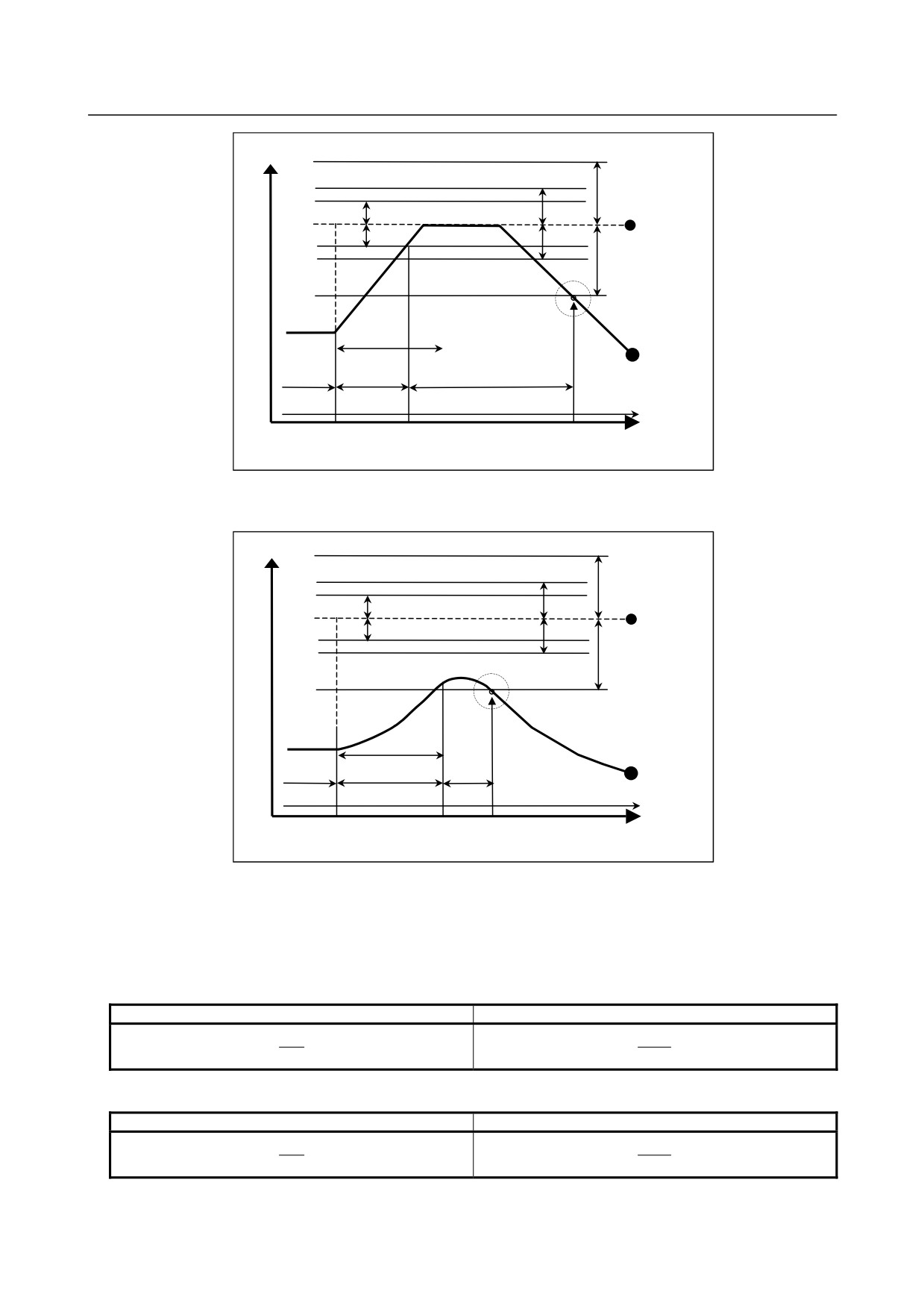
The function for detecting spindle speed fluctuation checks whether the actual speed varies for the
specified speed or not. Si or Sr, whichever is greater, is taken as the allowable fluctuation speed (Sm).
An alarm (OH0704) is activated when the actual spindle speed varies for the commanded speed (Sc)
under the condition that the variation width exceeds the allowable variation width (Sm).
|Sc - Sa| > Sm
Sc : Specified spindle speed
Sa : Actual spindle speed
Si : The allowable constant variation width which is independent of the specified spindle speed
(parameter (No.4913))
Sr : The allowable variation width which is obtained by multiplying Sc (commanded spindle speed)
by r (constant ratio). (r = parameter (No.4912))
Parameter FLR(No.4900#0)= 0
Parameter FLR(No.4900#0)= 1
r
r
Sr = Sc ×
Sr = Sc ×
100
1000
Sm: Si or Sr, whichever is greater
-
Conditions to start spindle speed fluctuation detection
If the specified spindle speed Sc changes, spindle speed fluctuation detection starts when one of the
conditions below is met:
<1> The actual spindle speed falls in a range of (Sc - Sq) to (Sc + Sq)
Sc : Specified spindle speed
Sq : Tolerance within which the spindle is assumed to attain the programmed speed
(parameter (No.4911))
Parameter FLR= 0
Parameter FLR= 1
q
q
Sq = Sc ×
Sq = Sc ×
100
1000
<2> When time p specified in parameter No. 4914 elapses after the specified speed Sc changes.
-
Examples of spindle speed fluctuation detection
(Example 1)
When an alarm (OH0704) is issued after a specified spindle speed is reached
- 108 -
9.SPINDLE SPEED FUNCTION
B-64304EN/02
PROGRAMMING
(S FUNCTION)
Spindle
speed
Sr
Sq
Si
Specified
Sq
Si
speed
Sr
P
Actual
CHECK
NO CHECK
CHECK
speed
G26 mode
Time
Specification of
Start of check
Alarm
another speed
(Example 2)
When an alarm OH0704 is issued before a specified spindle speed is reached
Spindle
speed
Sr
Sq
Si
Specified
speed
Sq
Si
Sr
P
CHECK NO CHECK CHECK
Actual
speed
G26 mode
Time
Specification of
Start of Alarm
another speed
check
Specified speed
:
(Speed specified by address S and five-digit value) × (spindle override)
Actual speed
: Speed detected with a position coder
p
: Period after a change occurs in the actual spindle speed until detection starts
Parameter No.4914, address P
Sq
:
(Specified spindle speed)× (Detection start tolerance (q))
Parameter No.4911, address Q
Parameter FLR = 0
Parameter FLR = 1
q
q
100
1000
Sr
:
(Specified spindle speed) × (Allowable variation (r))
Parameter No.4912, address R
Parameter FLR = 0
Parameter FLR = 1
r
r
100
1000
Si
: Allowable variation width
Parameter No.4913, address I
- 109 -

9. SPINDLE SPEED FUNCTION
(S FUNCTION)
PROGRAMMING
B-64304EN/02
If the difference between the specified speed and actual speed exceeds both Sr and Si, an alarm OH0704
is raised.
-
Relationship between spindle speed control and each spindle
Spindle
Serial spindle
Function
1st spindle
2nd spindle
Spindle speed fluctuation detection
Possible
Possible(*1)
NOTE
1 It is necessary to enable multi spindle control (bit 3 (MSP) of parameter No.
8133 is 1).
2 The spindle speed fluctuation detection function is effective for a single spindle.
The function cannot be executed for two or more spindles.
The spindle speed fluctuation detection function is effective for a spindle on
which the currently selected position coder is mounted. Just a single position
coder can be selected. Multiple position coders cannot be selected. For the
selection of a position coder, see the section of "Multi spindle."
* Position coder selection signals (PC2SLC<Gn028.7>)
3 The parameters that become valid are the parameters of the spindle speed
fluctuation detection function (No.4911, No.4912, No.4913, No.4914) for the
spindle on which the currently selected position coder is mounted.
-
Spindle for which to detect the spindle speed fluctuation
For the spindle for which to detect the spindle speed fluctuation, refer to the appropriate manual provided
by the machine tool builder.
9.6
SPINDLE CONTROL WITH SERVO MOTOR
Overview
The function for spindle control with servo motor allows a servo motor to be used for executing spindle
speed commands and spindle functions such as rigid tapping.
(1) Spindle control with servo motor
Velocity control can be performed by using a speed command (S command) with a servo motor set
as the tool rotation axis. No reference position return is necessary to switch between rotation and
positioning commands.
(2) Spindle indexing
With the spindle indexing function, a stop position can be programmed to stop a rotating axis at the
specified position. There are two types of spindle indexing. The first type allows the next-block
command to be executed before spindle indexing is finished. The second type allows the next
block to be executed only after spindle indexing is completed.
With the first type, it is possible to issue commands to axes other than the axis for which a spindle
indexing command has been issued, before the next command is issued to the axis. Before the next
command is issued to the axis for which a spindle indexing command has been issued, whether
spindle indexing is completed or not can be checked by programming or by using a signal. Using
this function can reduce the wait time. In addition, an axis can be stopped at a specified point by
issuing a spindle indexing command to the axis when the spindle is rotating.
(3) Axis movement
When bit 0 (PCE) of parameter No. 11006 is 1, if axis movement (G00/G01) is specified for a servo
motor spindle in the same way as in a normal controlled axis, position control can be performed.
(4) Rigid tapping with servo motor
Rigid tapping can be carried out by regarding a servo motor spindle as a rotation axis.
(5) Threading, feed per rotation feed, and constant surface speed control
- 110 -

9.SPINDLE SPEED FUNCTION
B-64304EN/02
PROGRAMMING
(S FUNCTION)
Threading, feed per rotation feed, and constant surface speed control can be performed using a servo
motor spindle as a spindle.
(6) Spindle output control with PMC
The rotation speed and polarity can be controlled by PMC.
-
Spindle motors and supported functions
Spindle functions
Conventional spindle control
Spindle control with servo motor
Feed per revolution
○
○
Threading
○
○
Polygon machining
○
×*1
Spindle speed fluctuation detection
○
×
Spindle synchronous control
○
×
Simple spindle synchronous control
○
×
Polygon machining with two spindles
○
×
Spindle orientation
Multi-point orientation
○
×
Spindle output switching
Inter-path spindle control
○
○
Constant surface speed control
○
○
Multi-spindle control
○
○
Rigid tapping
○
○
Spindle output control with PMC
○
○
Actual spindle speed output
○
○
Spindle indexing
×
○
*1 Servo motor can be used as tool rotation axis.
It is not possible to use as a spindle which rotates workpiece.
Notes
(1) This function is optional.
(2) The available functions and spindle axis composition are predetermined according to the machine
used. Refer to the manual supplied by the machine tool builder.
(3) If necessary, refer to "SPINDLE CONTROL WITH SERVO MOTOR" in "CONNECTION
MANUAL (FUNCTION)" (B-64303EN-1).
9.6.1
Spindle Control with Servo Motor
Specification
-
Command with a program
This function can be used to specify the S spindle rotation command for a servo motor spindle in the SV
speed control mode. For rotation control of a servo motor, specify G96.4 to start the SV speed control
mode. Once the SV speed control mode is specified, the S command is valid for the servo motor until
the SV speed control mode is released. Do not specify a positioning command in the SV speed control
mode. Otherwise, alarm PS0445 is issued.
Before positioning operation, release the SV speed control mode. To release the SV speed control mode,
specify the spindle indexing command G96.1/G96.2. For details on spindle indexing, see "Spindle
Indexing Function". When bit 0 (PCE) of parameter No. 11006 is 1, a positioning command can be
specified. When bit 0 (PCE) of parameter No. 11006 is 0, a positioning command cannot be specified
for a servo motor spindle. If specified, alarm PS0601 is issued.
In a mode other than the SV speed control mode, the S command is invalid. However, since information
of the S command is recorded, if the SV speed control mode is entered, rotation starts at the specified
rotation speed.
- 111 -
9. SPINDLE SPEED FUNCTION
(S FUNCTION)
PROGRAMMING
B-64304EN/02
-
Command with a signal
SV speed control mode signal <Gn521> can also be used to start and cancel the SV speed control mode.
The SV speed control mode is started or canceled on a rising or falling edge of the SV speed control
mode signal. Therefore, to start the SV speed control mode again after the SV speed control mode is
started by using the signal then canceled by a programmed command, input the SV speed control mode
signal again or specify G96.4.
The SV speed control mode status can be checked using the SV speed control mode in-progress signals
<Fn521>.
When the signal is set to 0 during rotation, spindle indexing is performed, then the SV speed control
mode is canceled. Spindle indexing performs positioning to R0 (absolute value 0). For spindle
indexing, see Subsection II-9.6.2, "Spindle Indexing Function".
Format
G96.4 P_ ;
Start SV speed control mode
M03(M04) S_ P_ ; Rotation command
S: Spindle speed [min-1] (numeric value of up to five digits)
P: Spindle selection with multi-spindle control
-
Starting the SV speed control mode
When multi-spindle control is enabled and a spindle is selected with address P (Bit 3 (MPP) of parameter
No. 3703 = "1"), the SV speed control mode can be started by specifying G96.4 and spindle selection
command P. To specify address P, use parameter No. 3781 (P code for selecting a spindle). When a
spindle is selected with spindle selection signals SWS1 to SWS2 <Gn027.0 to Gn027.1>, it is possible to
start the SV speed control mode if spindle selection signal is input when program is analyzed in the G96.4
command block. In any case, when a servo motor spindle has not been selected in the G96.4 command
block, alarm PS0602 is issued.
When multi-spindle control is disabled, it is possible to start the SV speed control mode if G96.4 is
independently commanded. When there is no servo motor spindle in the system, alarm PS0602 is issued.
-
Canceling the SV speed control mode
When multi-spindle control is enabled and a spindle is selected with address P (Bit 3 (MPP) of parameter
No. 3703 = "1"), the SV speed control mode can be canceled by specifying a spindle indexing command
(G96.1/G96.2) and spindle selection command P. When a spindle is selected with spindle selection
signals SWS1 to SWS2 <Gn027.0 to Gn027.1>, it is possible to cancel the SV speed control mode if
spindle selection signal is input when program is analyzed in the spindle indexing command
(G96.1/G96.2) block. In any case, when a servo motor spindle has not been selected, alarm PS0602 is
issued.
When multi-spindle control is disabled, it is possible to cancel the SV speed control mode if G96.4 is
independently commanded. When there is no servo motor spindle in the system, alarm PS0602 is issued.
For the command format of the spindle indexing command, see "Spindle Indexing Function".
-
Notes
To specify “G96.4 P_ ;”, use an independent block.
However, it is possible to specify "G96.4 P_ S_ ;".
Moreover, in 2-path system, when it is specified from paths other than the path that a servo motor spindle
belongs, alarm PS0602 is issued.
- 112 -
9.SPINDLE SPEED FUNCTION
B-64304EN/02
PROGRAMMING
(S FUNCTION)
Explanation
-
Command
(1) Spindle speed command output
Set up the spindle speed command in the same way as for the ordinary speed command (S
command). Before specifying a speed command (S command), start the SV speed control mode.
When performing positioning, cancel the SV speed control mode, and select the position control
mode.
The sequence by the following input signals is unnecessary.
*ESPA, MRDYA, and SFRA
(2) Condition for stopping spindle speed output
Commands once output to a spindle become 0 if *SSTP becomes “0” or if a command (such as S0)
that makes the spindle speed command output 0 is issued. Also, issuing a spindle indexing
command (G96.1/G96.2) makes the spindle speed command output 0. In addition, an emergency
stop condition and servo alarm bring the spindle to a stop.
With M05, the CNC does not make the command output to the spindle 0.
(3) Stopping rotation by spindle indexing
Issuing a command that specifies a position enables the rotating axis to stop at the specified position.
For details, see Subsection, "Spindle Indexing Function."
(4) Maximum speed
The maximum speed that can be specified is usually 2777 min-1.
However, setting bit 3 (IRC) of parameter No. 1408 to "1" may be able to increase the limit to about
27770 min-1 depending on the performance of the related motor and detector.
-
Multi-spindle control and commands from another path
When a servo motor spindle and another spindle are present together in the same path, the multi-spindle
control function is required to specify a rotation command. The path spindle control function can handle
commands from another path. The address P-based spindle select function for multi-spindle control can
be used to select spindles in another path.
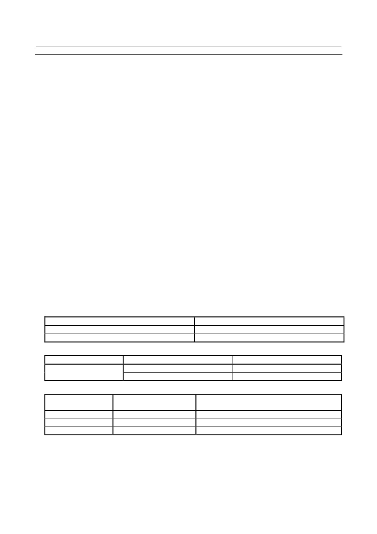
Example program commands follow.
Example 1:
(Spindle selection with address P)
Bit 3 (MPP) of parameter No. 3703 = "1": A spindle is selected with address P.
Spindle configuration (S1 = first spindle and S2 = second spindle)
Path 1
Path 2
S1 (spindle axis)
S3 (spindle axis)
S2 (servo motor spindle)
-
Setting address P for spindle selection in multi-spindle control
Parameter
Path 1
Path 2
11 (S1)
21 (S3)
3781
12 (S2)
-
Program example
Command issuing
Program
Operation
path
1
M03 S1000 P12 ;
S2 rotates in normal direction at 1000 min-1.
1
M03 S1500 P21 ;
S3 rotates in normal direction at 1500 min-1.
2
M04 S1500 P11 ;
S1 rotates in reverse direction at 1500 min-1.
-
Manual operation of a servo motor spindle
Before performing the manual operation and manual reference position return of a servo motor spindle,
release the SV speed control mode. Manual operation and manual reference position return in the SV
speed control mode are invalid.
- 113 -
9. SPINDLE SPEED FUNCTION
(S FUNCTION)
PROGRAMMING
B-64304EN/02
When using an absolute position detector, manual reference position return is not required. If reference
position return (G28) is performed in a program when position control is disabled (bit 0 (PCE) of
parameter No. 11006 is 0), alarm PS0601 is issued.
NOTE
If a movement command is specified for a servo motor spindle when position
control is disabled (bit 0 (PCE) of parameter No. 11006 is 0), alarm PS0601 is
issued.
-
Acceleration/deceleration (time constant)
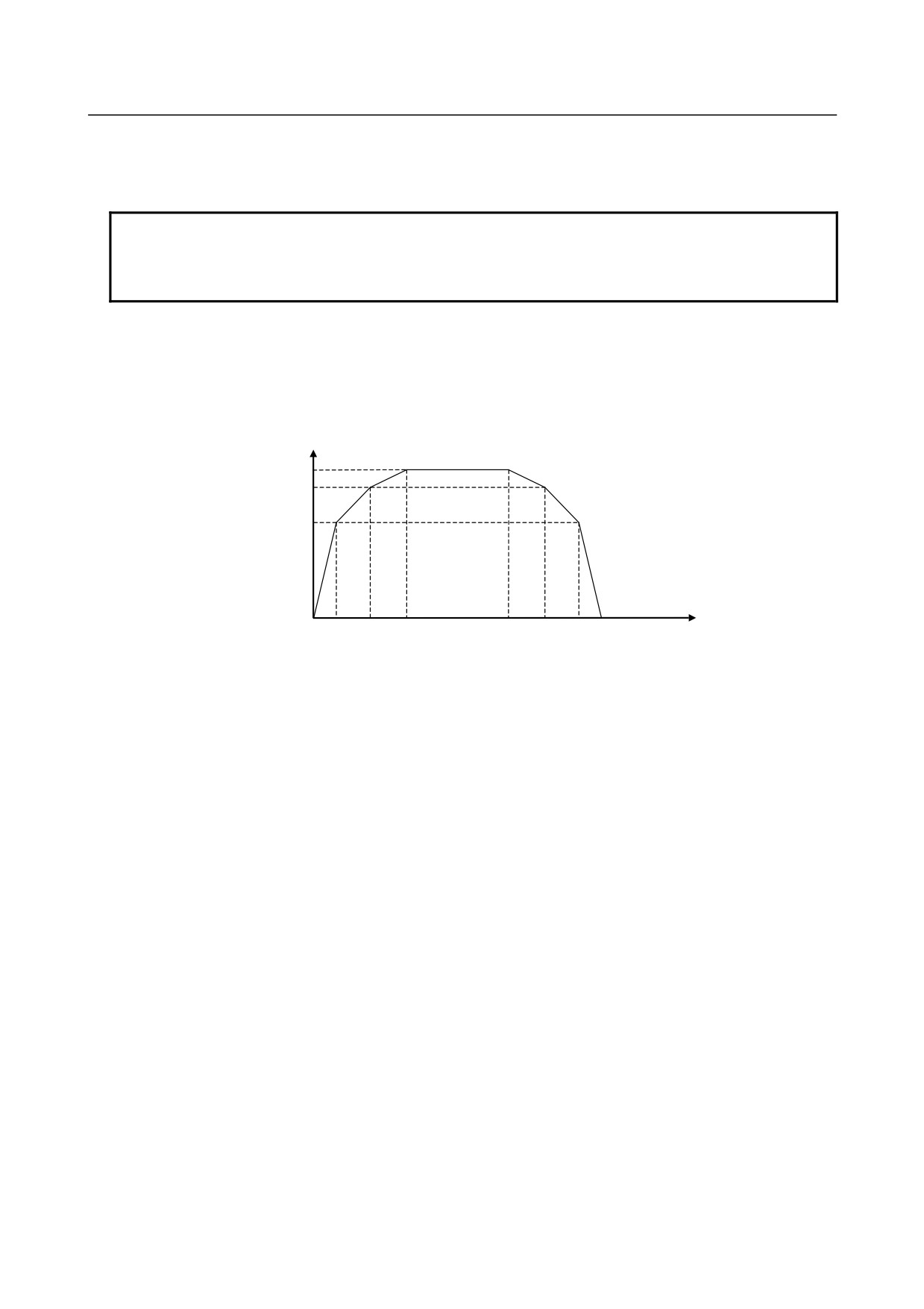
It is possible to change the spindle acceleration/deceleration specified in a rotation command according to
the speed of the spindle.
Acceleration/deceleration can be switched at two points of speed, using parameters S0 and S1 (switching
speed). In addition, parameters Aa, Ab, and Ac are available to set up three acceleration/deceleration
spans.
Rotation
speed (min-1)
Ac
S
S1
Ab
S0
Aa
Time (s)
S0
: Setting of parameter No. 11020 (acceleration/deceleration is switched at rotation speed S0 (min-1)).
S1
: Setting of parameter No. 11021 (acceleration/deceleration is switched at rotation speed S1 (min-1)).
S
: Specified rotation speed (min-1).
Aa
: Setting of parameter No. 11030 (acceleration/deceleration (min-1/s) used between rotation speeds 0
and S0).
Ab : Setting of parameter No. 11031 (acceleration/deceleration (min-1/s) used between rotation speeds
S0 and S1).
Ac
: Setting of parameter No. 11032 (acceleration/deceleration (min-1/s) used between S1 and the
specified speed S).
Determine the setting of each parameter according to the torque characteristic of the motor.
-
Acceleration/deceleration after interpolation
Acceleration/deceleration after interpolation is available in the SV speed control mode. Bit 1 (TCR) of
parameter No.11001 can be used to select a time constant type, that is, parameter No. 1622
(Time constant of acceleration/deceleration in cutting feed for each axis) or parameter No. 11016 (Time
constant of acceleration/ deceleration in SV speed control mode for each axis).
-
Direction of rotation
The voltage polarity at the time of spindle speed output can be changed using bit 6 (CWM) and bit 7
(TCM) of parameter No. 3706.
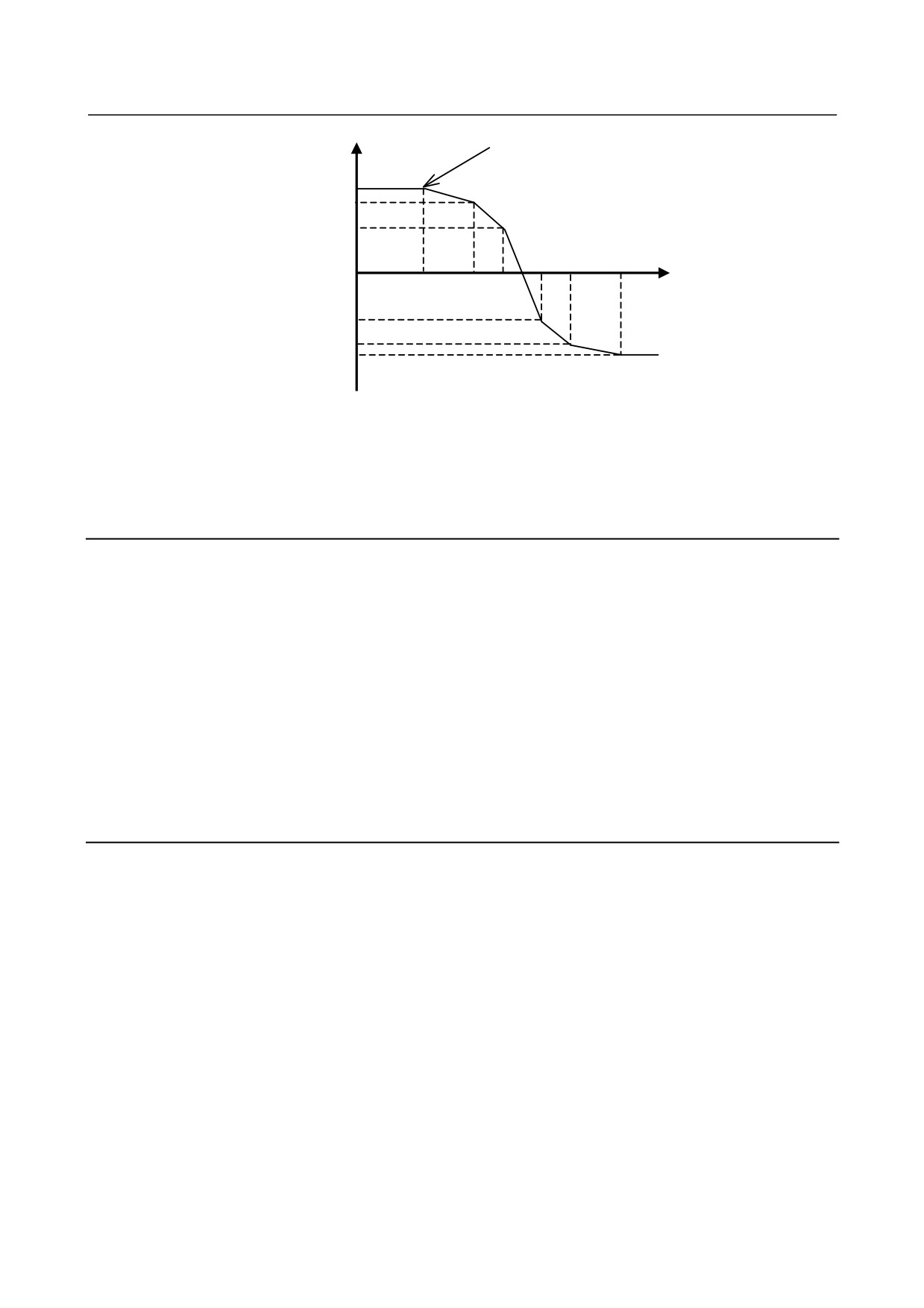
It is also possible to reverse the direction of spindle rotation, using the SV reverse signal <Gn523>.
These functions are usable in the rotation mode and during rigid tapping. Changing the signal to
ON/OFF during rotation causes the spindle to decelerate, reverse, and then accelerate.
- 114 -
9.SPINDLE SPEED FUNCTION
B-64304EN/02
PROGRAMMING
(S FUNCTION)
Rotation
SV reverse signal ON
speed (min-1)
S
Ac
S1
Ab
S0
Aa
0
Aa
-S0
Ab
-S1
-S
Ac
Time (sec)
-
Display
Bit 3 (NDF) of parameter No. 3115 can be used to specify whether to display the actual speed. This,
however, is not considered in the SV speed control mode regardless of the setting of the NDF parameter
bit. In addition, bits 0 (NDP) and 1 (NDA) of parameter No. 3115 can be used to specify whether to
display, respectively, the current position and the remaining amount of movement.
Restrictions
(1) When multi-spindle control is enabled, in settings other than multi-spindle P type, specifying G96.*
P is regarded as invalid.
(2) When starting or canceling the SV speed control mode during automatic operation, be sure to
specify the path of the target axis of the SV speed control mode. When it is specified from the other
path, alarm PS0602 is issued.
(3) Be sure to set M code which starts or cancels the SV speed control mode to M code preventing
buffering (parameter No.3411 to 3420, No.3421 to 3432).
(4) When the SV speed control mode is started or cancelled except for automatic operation, be sure to
perform manual reference position return before starting the automatic operation so that the target
axis lose its reference position.
The axis may not move correctly to the commanded position in SV speed control cancel mode
(position control mode) when the automatic operation is started without performing manual
reference position return.
Notes
(1) This function is optional.
(2) The available functions and spindle axis composition are predetermined according to the machine
used. Refer to the manual supplied by the machine tool builder.
(3) If necessary, refer to "Spindle Control with Servo Motor" in "CONNECTION MANUAL
(FUNCTION)" (B-64303EN-1).
(4) Unlike spindle motors, a servo motor spindle stops rotating when a servo alarm, an emergency stop,
or a machine lock occurs.
(5) The maximum motor speed is obtained by applying the feed gear to the maximum motor speed set in
parameter No. 11015.
(6) If bit 3 (IRC) of parameter No. 1408 is set to 0, the error prevention function may work when the
speed has reached around 2778 min-1. When a speed of 2778 min-1 or more is required, set the IRC
parameter bit to 1. If IRC is set to 1, it becomes possible to specify a speed of up to approximately
27770 min-1.
- 115 -

9. SPINDLE SPEED FUNCTION
(S FUNCTION)
PROGRAMMING
B-64304EN/02
9.6.2
Spindle Indexing Function
Format
G96.1 P_ R_ ; After spindle indexing is completed, the operation of the next block is
started.
G96.2 P_ R_ ; Before spindle indexing is completed, the operation of the next block
is started.
G96.3 P_ ;
After it is confirmed that spindle indexing is completed, the operation
of the next block is started.
P: Spindle selection with multi-spindle control
R: Stoppage angle [deg] (0 to (parameter No. 1260))
When multi-spindle control is enabled, select a spindle according to the specification of multi-spindle
control along with the G96.1/G96.2/ G96.3 command. When a spindle is selected with address P, to
specify address P, use parameter No. 3781 (P code for selecting a spindle). In any case, when a servo
motor spindle has not been selected, alarm PS0602 is issued.
When multi-spindle control is disabled, it is possible to command G96.4 independently. When there is no
servo motor spindle in the system, alarm PS0602 is issued.
In 2-path system, when it is specified from paths other than the path that a servo motor spindle belongs,
alarm PS0602 is issued.
To turn the position control mode ON without performing spindle indexing, do so after canceling the SV
speed control mode by issuing G96.1 command with no R specified when the motor is at a halt.
When the motor is rotating, issuing a G96.1 (or G96.2) command with no R specified results in the motor
coming to a halt by behaving in the same manner as for R0.
NOTE
1 When having specified G96.2, check the completion of the movement by
specifying G96.3 before specifying the next move command for the spindle. If
the next move command is specified without confirming the completion of the
movement, alarm PS0601 is issued. Similarly, if rigid tapping is specified
without confirming the completion of the movement, alarm PS0445 is issued.
2 A block specifying G96.1, G96.2, or G96.3 must not contain any other command.
If an axis command is specified in the same block, alarm PS0446 is issued.
-
Reference position return
Before executing the first command of spindle indexing to the tool rotation axis with a servo motor, be
sure to perform a manual reference position return. When the absolute-position detector is used,
however, a manual reference position return is not necessary. When the reference position return
command (G28) is executed in a program, alarm PS0601 is issued.
Spindle indexing command
-
Move command
(1) Command waiting for spindle indexing to be completed
If G96.1 is issued, the next block is executed after spindle indexing is completed.
(2) Command not waiting for spindle indexing to be completed
If G96.2 is issued, the next block can be executed before spindle indexing is completed.
-
Movement completion check command
G96.3 is used to check to see if spindle indexing is completed. If it has not been completed, the next
block waits for spindle indexing to be completed. If it is completed, the next block is executed.
- 116 -

9.SPINDLE SPEED FUNCTION
B-64304EN/02
PROGRAMMING
(S FUNCTION)
-
SV speed control mode cancellation
If G96.1 is used to perform spindle indexing, the SV speed control mode is canceled when spindle
indexing is completed.
If G96.2 is used to perform spindle indexing, G96.3 can be used to check to see if spindle indexing is
completed and, if completed, cancel the SV speed control mode. Issuing G96.2 not followed by G96.3
cannot cancel the SV speed control mode even if spindle indexing is completed.
If SV speed control mode cancel, it is necessary to be commanded in the path to which the live tool axis
belongs.
Example for specifying the start/cancellation of the SV speed control mode (when bit 3 (MPP) of parameter
No. 3703 = 1)
Spindle
Spindle selection P code
Servo motor spindle address
name
(parameter No. 3781)
S1
P1
C
Specification by programming (SV speed control mode in-progress signal <Fn521>)
Programmed
Start/cancellation of speed control mode
Operation
command
Start (SV speed control mode in-progress
G96.4 P1 ;
The SV speed control mode is started (C).
signal (C) = 1)
Servo motor spindle C turns in the forward
M03 S100 P1 ;
:
direction at 100 [min-1].
:
:
:
Cancel (SV speed control mode in-progress
The servo motor spindle C stops when C = 0
G96.1 P1 R0 ;
signal (C) = 0)
(spindle indexing).
Mode switching by signal
Programmed
Start/cancellation of speed control mode
Operation
command
Start (SV speed control mode in-progress
The SV speed control mode is started by the M
M15 ;
signal (C) = 1)
code (C).
Servo motor spindle C turns in the forward
M03 S100 P1 ;
:
direction at 100 [min-1].
:
:
:
Cancel (SV speed control mode in-progress
The servo motor spindle C stops when C = 0
G96.1 P1 R0 ;
signal (C) = 0)
(spindle indexing).
-
Spindle indexing command during spindle rotation
Issuing G96.1 or G96.2 with a position specified during spindle rotation causes the spindle to stop at the
specified position.
Example)
M03 S1000 ;
Rotation at S1000
G96.1 P1 R180. ;
Stoppage of rotation at the 180° position
-
Spindle indexing speed
Issuing G96.1 or G96.2 causes a move speed to be dedicated to spindle indexing. Specify the move
speed for spindle indexing, using parameter No. 11012.
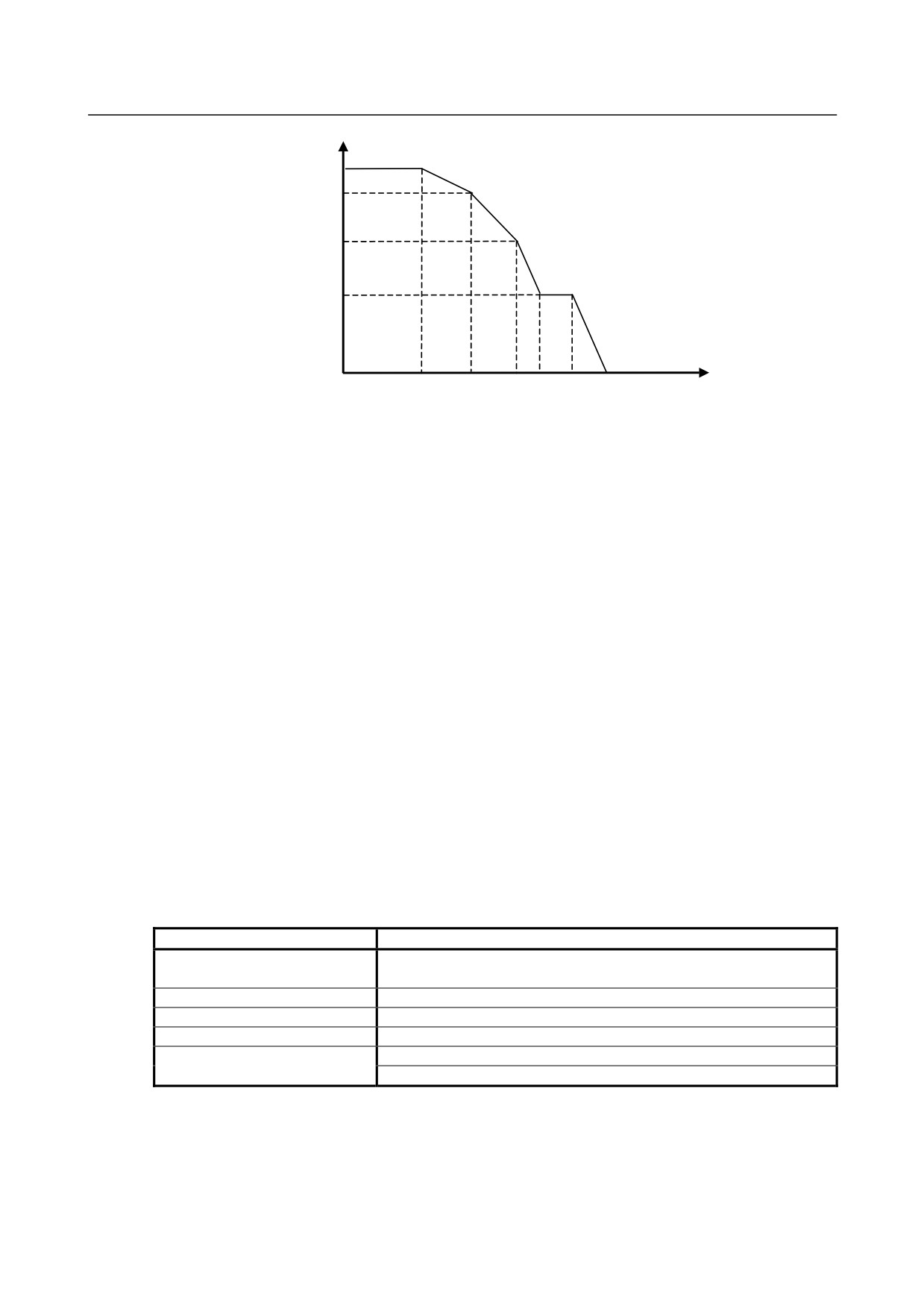
- Spindle indexing acceleration/deceleration
Shown below is the acceleration/deceleration specified by G96.1/G96.2.
- 117 -
9. SPINDLE SPEED FUNCTION
(S FUNCTION)
PROGRAMMING
B-64304EN/02
Rotation
speed (min-1)
A
c
S
S1
Ab
S0
Aa
Si
Aa
Time (s)
S1
: Parameter No. 11020 setting
(acceleration/deceleration is switched at a rotation speed of S1
(min-1).)
S0
: Parameter No. 11021 setting
(acceleration/deceleration is switched at a rotation speed of S0
(min-1).)
S
: Command-specified rotation speed (min-1)
Si
: Spindle indexing speed (min-1) parameter No. 11012
Aa
: Parameter No. 11030 setting (acceleration/deceleration (min-1/s) used between rotation speeds 0
and S0 (span 1))
Ab
: Parameter No. 11031 setting (acceleration/deceleration (min-1/s) used between rotation speeds S0
and S1 (span 2))
Ac
: Parameter No. 11032 setting (acceleration/deceleration (min-1/s) used between S1 and a specified
speed S (span 3)))
-
Example program commands
(1) A move command is issued to the spindle, using G96.2. The spindle starts moving, and the
execution of the next block begins.
The spindle keeps moving even when any other block is being executed.
(The spindle indexing signal SPP<Fn522> is "1" during spindle indexing.)
(2) When another command is issued to the spindle, G96.3 is used to heck in advance whether the
spindle has finished moving.
If the spindle is still moving (the spindle indexing signal is on), the CNC enters a wait state. If the
spindle has finished moving, the command is issued to cause the spindle to start moving.
Example: Command not waiting for spindle indexing to finish and command checking whether spindle
indexing has finished (parameter No. 3781 (S1) = "1")
Program command
Operation
Command not waiting for spindle indexing to finish.
G96.2 P1 R270.0
;
The first spindle S1 moves to 270.0.
G01 X10.0 Y20.0 F1000. ;
Starts cutting feed. No wait for spindle indexing to finish.
G02 X50.0 Y100.0 R50.0 ;
Starts circular interpolation. No wait for spindle indexing to finish.
G96.3 P1 ;
Checks whether spindle indexing has finished.
M29 S100 P1 ;
Starts rigid tapping if the spindle indexing signal is "0".
G84 X10.0 Y 20.0 R-5.0 Z-20.0 ;
Waits for rigid tapping command if the spindle indexing signal is "1".
Indexing by machine coordinates
In the function for spindle control with servo motor, the following operations can be selected:
(1) When the speed control mode is off, indexing to machine coordinate 0.000 is performed.
(2) When G code-based spindle indexing has been performed, an R command indicates a machine
coordinate value.
- 118 -

9.SPINDLE SPEED FUNCTION
B-64304EN/02
PROGRAMMING
(S FUNCTION)
Spindle indexing operation
Using bit 0 (SIC) of parameter No. 11005 can select which coordinate system, absolute or machine, is to
be used in spindle indexing.
Example:
If the difference between the machine and absolute coordinates (machine coordinate - absolute
coordinate) is 100.000:
•
Spindle indexing performed by turning the SV speed control mode signal <Gn521> OFF (1
t
0) or issuing a spindle indexing
G code (with no R specified)
1.
If bit 0 (SIC) of parameter No. 11005 = 0:
Spindle indexing is performed with a machine coordinate of 100.000 and an absolute
coordinate of 0.000.
2.
If bit 0 (SIC) of parameter No. 11005 = 1:
Spindle indexing is performed with a machine coordinate of 0.000 and an absolute
coordinate of 260.000.
•
G code-based spindle indexing (with R specified)
Assuming that spindle indexing is specified with R100.000:
1.
If bit 0 (SIC) of parameter No. 11005 = 0:
Spindle indexing is performed with a machine coordinate of 200.000 and an absolute
coordinate of 100.000.
2.
If bit 0 (SIC) of parameter No. 11005 = 1:
Spindle indexing is performed with a machine coordinate of 100.000 and an absolute
coordinate of 0.000.
Notes
(1) If G96.2 (not waiting for spindle indexing to finish) is issued, G96.3 must be issued to check
whether spindle indexing has finished. Be sure to issue G96.3 after G96.2. If a movement along
an axis is specified without checking (without issuing the G96.3 command), alarm PS0601 is issued.
Similarly, if rigid tapping is specified, alarm PS0445 is issued.
(2) If it has not been checked, for example, because of a reset, whether spindle indexing has finished
after G96.2 (not waiting for spindle indexing to finish) is issued, the SV speed control mode is not
canceled.
(3) If the spindle stops rotating because of spindle indexing, the spindle speed command output
becomes 0. To cause the spindle to restart rotating, place the spindle in the SV speed control mode,
and then, issue an S command.
(4) Spindle indexing is enabled only in the SV speed control mode.
(5) When the spindle indexing speed (parameter No. 11012) is 0, the acceleration/deceleration switching
speed
(1st step)
(parameter No.
11020) is the spindle indexing speed.
When the
acceleration/deceleration switching speed is also 0, the maximum speed (parameter No. 3741) of
each spindle that corresponds to gear 1 is the spindle indexing speed.
(6) The G96.* P command is invalid for settings other than multi-spindle control type P.
(7) The SV speed control mode during automatic operation must be switched by a command from the
path to which it belongs. When it is specified from the other path, alarm PS0602 is issued.
9.6.3
Rigid Tapping with Servo Motor
Format
The command format for this type of rigid tapping is the same as for the conventional type of rigid
tapping.
For details, refer to the chapter of "RIGID TAPPING" in the OPERATOR’S MANUAL (Lathe System)
(B-64304EN-1) or OPERATOR’S MANUAL (Machining Center System) (B-64304EN-2).
- 119 -
9. SPINDLE SPEED FUNCTION
(S FUNCTION)
PROGRAMMING
B-64304EN/02
NOTE
Before rigid tapping can be specified, the SV speed control mode for the servo
motor spindle must be canceled. If rotation is in progress, use G96.1/G96.2 to
cancel the SV speed control mode. The mode of the servo motor spindle can
be checked by checking the SV speed control mode in-progress signal
(SVREV<Fn521>).
If rigid tapping is specified in the SV speed control mode, alarm PS0445 is
issued.
Rigid tapping specification
- Feedrate
For rigid tapping, the feedrate of a drilling axis is one specified in an F command, and that of the spindle
is S × the amount of movement per live tool axis (servo motor spindle) rotation [deg/min] (parameter No.
11011).
Feed per minute and feed per revolution are detailed later.
During rigid tapping, the spindle speed is limited by a parameter for specifying the maximum cutting
feedrate for the axis used as a live tool axis, that is, parameter No. 1430 (or No. 1432 if acceleration/
deceleration before interpolation is enabled).
Normally, the parameter of the maximum cutting feedrate (parameter No. 1430) (parameter No. 1432
when acceleration/deceleration before interpolation is enabled) can be set to up to 999999.999 [deg/min]
(equivalent to S2778 [min-1]). However, for an axis set as the live tool axis (bit 3 (IRC) of parameter No.
1408 = 1) that is used for rigid tapping, the maximum feedrate is limited to ten times as large as the
setting of the maximum cutting feedrate parameter.
Example:
Maximum cutting feedrate parameter No. 1430 = 360000
Limit to the maximum spindle speed 360000×10 = 3600000 [deg/min] (S10000 [min-1])
CAUTION
Make the tapper thread pitch equal to one specified by the program (F, S).
Otherwise, the tool or workpiece may be damaged.
Acceleration/deceleration control
-
Acceleration/deceleration after interpolation
Unlike conventional rigid tapping (with a spindle motor), rigid tapping with a servo motor allows the
application of linear acceleration/deceleration with constant acceleration/deceleration time or bell-shaped
acceleration/deceleration.
Resetting bit 0 (SRBx) of parameter No. 11001 to "0" makes it possible to apply linear
acceleration/deceleration after interpolation of constant acceleration time type. Setting the bit to "1"
makes it possible to apply bell-shape acceleration/deceleration after interpolation of constant acceleration
time type.
The time constant for each gear is specified in parameter Nos. 11060 to 11063. If bit 2 (TDR) of
parameter No. 5201 = "1", the tool extraction time constant for each gear is specified in parameter
Nos. 11065 to 11068. Specify each of these parameters for the live tool axis (servo motor spindle) used
in rigid tapping.
The acceleration/deceleration types and time constants used for drilling axes are set to the same values as
for live tool axes (servo motor spindles).
NOTE
This type of rigid tapping and conventional rigid tapping (with a spindle motor)
differ in time constant setting.
- 120 -
9.SPINDLE SPEED FUNCTION
B-64304EN/02
PROGRAMMING
(S FUNCTION)
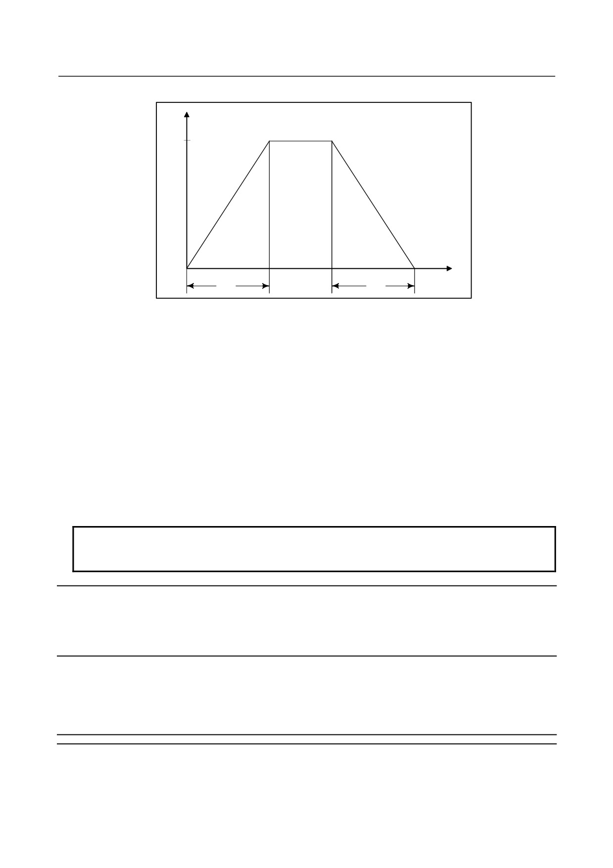
Example: Parameter settings are: Time constant (TC) = 800 msec and speed (S) = 4000 min-1
min-1
4000
800
800
msec
-
Acceleration/deceleration before interpolation
In this type of rigid tapping, when advanced preview control can be used, rigid tapping can be specified
in the mode for acceleration/deceleration before look ahead interpolation to allow
acceleration/deceleration
before
look
ahead
interpolation
during
rigid
tapping.
Acceleration/deceleration before look ahead interpolation is enabled when the advanced preview control
mode is set to on. For the advanced preview control function, see "High-Speed High-Precision Function
(Advanced Preview Control)".
Parameter No. 11050 is used to specify the maximum allowable acceleration value for
acceleration/deceleration interpolation used in rigid tapping. Parameter No. 11051 is used to specify the
acceleration change time for bell-shape acceleration/deceleration before interpolation. As for
acceleration/deceleration before interpolation used in rigid tapping, the maximum allowable acceleration
value is 100000 [deg/s2].
It is possible to change a speed of up to S1000 [min-1] (equivalent to 360000 [deg/min] in 60 [ms].
The time constant (parameter No. 11052) for cutting feed acceleration/deceleration after interpolation
usable in the "acceleration/deceleration before look-ahead interpolation" mode is a constant-time type.
NOTE
Specify the same time constant for both drilling and live tool axes (servo motor
spindle). Otherwise, it is likely that the machine may malfunction.
Spindle indexing
This function does not allow the spindle orientation function to be performed at the start of rigid tapping.
Before specifying rigid tapping, perform spindle indexing to the position at which tapping is to be
performed. For details, see "Spindle Indexing Function" described previously.
Notes
If the pitch is very small or the amount of travel along the drilling axis is large, the amount of travel along
the rotation axis becomes large, possibly resulting in alarm PS0003.
9.6.4
Feed per Revolution
Overview
The function for spindle control with servo motor allows a feed per revolution to be specified.
- 121 -
9. SPINDLE SPEED FUNCTION
(S FUNCTION)
PROGRAMMING
B-64304EN/02
From the separate detector connected to the spindle, the rate of feed per revolution is obtained. When
the detector built into the servo motor is to be used, the feedrate is obtained based on the servo motor
speed and gear ratio.
Which detector to use is specified by bit 1 (OPTx) of parameter No. 1815.
NOTE
If the machine is equipped with a live tool axis and spindle with servo motor,
using rotation commands requires the multi-spindle control function.
As for gear change, use T type gear change.
See Section, “MULTI-SPINDLE CONTROL,” in Connection Manual (Function)
(B-64303EN-1) for explanations about multi-spindle control.
Format
The command format for feed per revolution explained above is the same as for the ordinary types of feed
per revolution.
-
Examples
When the second spindle (C-axis) is used for rotation control and position control with the second spindle
assumed to be a servo motor spindle
(The G code system A in lathe system is selected.)
Program command
Operation
M*** ;
The C axis rotation control mode is turned ON.
M03 S100 P2 ;
The servo motor spindle (C axis) rotates at 100 min-1.
G99 G01 Z-100. F10. ;
The Z axis moves at a feed-per-revolution speed of 1000 mm/min.
:
:
The C axis position control mode is set to ON (rotation control mode OFF).
M*** ;
The spindle stops with C = 0.000.
9.6.5
Spindle Output Control with PMC
Overview
The “spindle control with servo motor” function enables the PMC to be sued for spindle output control.
How to specify
After the start of the SV speed control mode, this function can be specified in the same way as in ordinary
spindle control (with a spindle motor).
Refer to Section,
“SPINDLE OUTPUT CONTROL BY THE PMC,” in this manual for detailed
descriptions.
NOTE
For the “spindle control with servo motor” function, the maximum motor speed is
one specified in parameter No.11015.
- 122 -
B-64304EN/02
PROGRAMMING 10.TOOL FUNCTION (T FUNCTION)
10 TOOL FUNCTION (T FUNCTION)
Chapter 10, "TOOL FUNCTION (T FUNCTION)", consists of the following sections:
10.1 TOOL SELECTION FUNCTION
123
10.2 TOOL LIFE MANAGEMENT
124
10.1 TOOL SELECTION FUNCTION
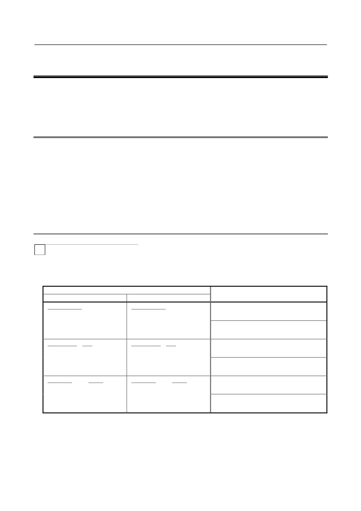
By specifying an up to 8-digit numerical value following address T, a code signal and a strobe signal are
transmitted to the machine tool. This is used to select tools on the machine.
One T code can be commanded in a block. Refer to the machine tool builder's manual for the number of
digits commendable with address T and the correspondence between the T codes and machine operations.
When a move command and a T code are specified in the same block, the commands are executed in one
of the following two ways:
(i)
Simultaneous execution of the move command and T function commands.
(ii) Executing T function commands upon completion of move command execution.
The selection of either (i) or (ii) depends on the machine tool builder's specifications. Refer to the
manual issued by the machine tool builder for details.
Explanations
T
The value after the T code indicates the desired tool. Part of the value is also used as a tool offset
number that specifies the amount of tool offset or the like. The tool can be selected as follows according
to the specification method and parameter settings.
Description of a T code (Note 1)
How to specify the offset number for each
LGN (No.5002#1) = 0
LGN (No.5002#1) = 1
parameter setting (Note 2)
T{{{{{{{
{
T{{{{{{{
{
The tool wear offset number is specified using
↑
↑
↑
↑
the low-order one digit of a T code.
Tool selection Tool geometry
Tool selection Tool wear
tool wear
tool geometry offset
When parameter (No.5028) is set to 1
offset
offset
T{{{{{{
{{
T{{{{{{
{{
The tool wear offset number is specified using
↑
↑
↑
↑
the low-order two digits of a T code.
Tool selection Tool geometry
Tool selection Tool wear
tool wear
tool geometry offset
When parameter (No.5028) is set to 2
offset
offset
T{{{{{
{{{
T{{{{{
{{{
The tool wear offset number is specified using
↑
↑
↑
↑
the low-order three digits of a T code.
Tool selection Tool geometry
Tool selection Tool wear
tool wear
tool geometry offset
When parameter (No.5028) is set to 3
offset
offset
- 123 -
10.TOOL FUNCTION (T FUNCTION) PROGRAMMING
B-64304EN/02
NOTE
1 The maximum number of digits of a T code can be specified by parameter
(No.3032) as 1 to 8.
2 When parameter (No.5028) is set to 0, the number of digits used to specify the
offset number in a T code depends on the number of tool offsets.
Example)
When the number of tool offsets is 1 to 9:
Low-order one digit
When the number of tool offsets is 10 to 99:
Low-order two digits
When the number of tool offsets is 100 to 200: Low-order three digits
Refer to the machine tool builder's manual for correspondence between the T-code and the tool and the
number of digit to specify tool selection.
Example (T2+2)
N1 G00 X1000 Z1400 ;
N2 T0313 ;
(Select tool No. 3 and tool offset value No. 13)
N3 X400 Z1050 ;
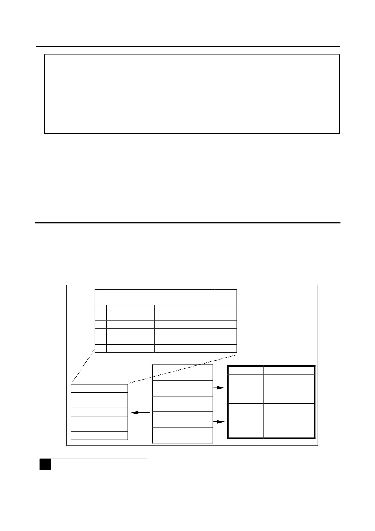
10.2 TOOL LIFE MANAGEMENT
Tools are classified into several groups, and a tool life (use count or use duration) is specified for each
group in advance. Each time a tool is used, its life is counted, and when the tool life expires, a new tool
that is sequenced next within the same group is selected automatically. With this function, the tool life
can be managed while machining is being performed continuously. Data for tool life management
consists of tool group numbers, tool life values, tool numbers, and codes for specifying a tool offset value.
These data items are registered in the CNC.
Tool group number m
Tool life value l
1
Tool number (T)
Code for specifying tool offset
1st-tool management data
value (H/D)
2
:
:
2nd-tool management data
:
:
:
:
:
:
:
:
n
:
:
nth-tool management data
Machining program
Machine and CNC operations
:
Machine
CNC
Tool life
:
Places a
Automatically
management data
selected tool
selects, from tool
Command for selecting
Tool group number 1
in the wait
group m, a tool
tool group m
state.
whose life has not
:
Select
:
expired.
:
Attaches the
Starts counting the
tool.
:
Tool group number m
tool in the
life of the tool
Tool change command
wait state to
attached to the
:
(M06)
the spindle
spindle.
:
(tool
:
change).
Tool group number p
:
Fig. 10.2 (a) Tool selection from machining program
M
A group is selected by a T code, and tool life counting is started by the M06 command. (ATC type)
- 124 -
B-64304EN/02
PROGRAMMING 10.TOOL FUNCTION (T FUNCTION)
T
A group is selected, tool compensation is specified, and tool life counting is started only by a T code.
(turret type)
-
Maximum number of tool life management groups and 2-path system
A maximum of 128 tool life management groups can be used for each path.
For each path, set a maximum number of groups to be used in parameter No. 6813.
The maximum number of groups must be a multiple of the minimum number of groups (eight groups).
A setting of 0 indicates 128 groups.
CAUTION
When parameter No. 6813 is changed and the power is turned on, all data in the
tool life management file is initialized. So, it is necessary to set life
management data for all paths that use tool life management.
10.2.1 Tool Life Management Data
Tool life management data consists of tool group numbers, tool numbers, codes for specifying a tool
offset value, and tool life values.
Explanation
- Tool group number
A maximum of 128 tool life management groups can be used for each path.
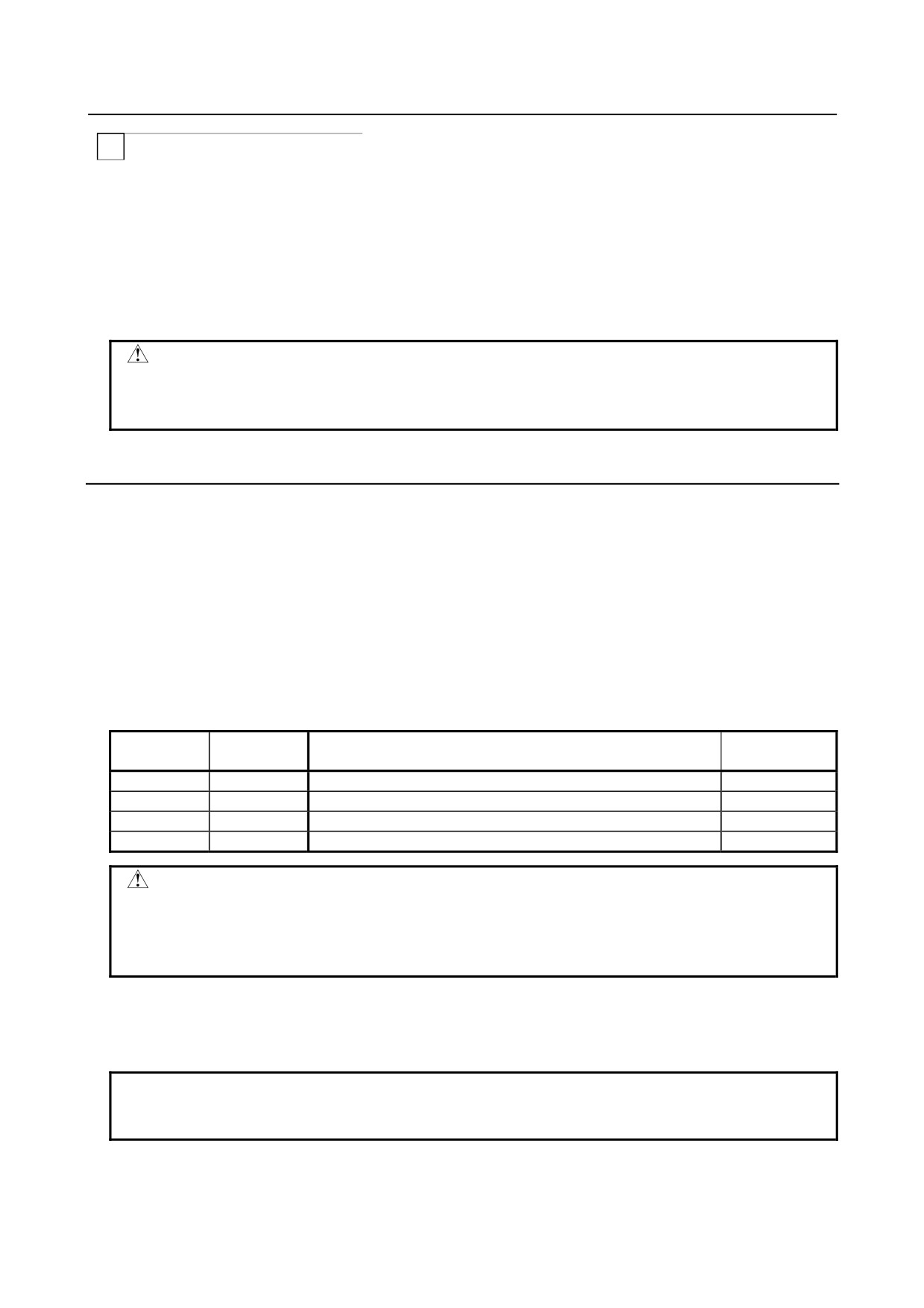
Set the maximum number of groups to be used in parameter No. 6813. Up to two tools can be registered
for each of a maximum number of groups. If bit 0 (GS1) of parameter No. 6800 and bit 1 (GS2) of
parameter No. 6800 is set, it is possible to change the combination of the number of registrable groups
and the maximum number of tools.
Table 10.2.1 Maximum numbers of registrable groups and tools
GS2
GS1
Number of groups
Number of tools
(No. 6800#1)
(No. 6800#0)
0
0
1 to Maximum number of groups (parameter No.6813) x 1/8
1 to 16
0
1
1 to Maximum number of groups (parameter No.6813) x 1/4
1 to 8
1
0
1 to Maximum number of groups (parameter No.6813) x 1/2
1 to 4
1
1
1 to Maximum number of groups (parameter No.6813)
1 to 2
CAUTION
After changing the setting of bit 0 (GS1) and bit 1 (GS2) of parameter No. 6800,
re-register tool life management data by issuing the G10L3 (registration after
deletion of data for all groups).
Otherwise, the newly set combination does not become valid.
- Tool number
A tool number is specified with a T code. A number consisting of up to eight digits (99999999) can be
specified.
NOTE
The maximum number of digits usable in the T code is specified in parameter
No. 3032.
- 125 -