FANUC Series 16i/160i/160is-MB, Series 18i/180i/180is-MB5, Series 18i/180i/180is-MB. Operator's Manual - page 23
22. RISC PROCESSOR
PROGRAMMING
B-63534EN/02
Tool
Tool
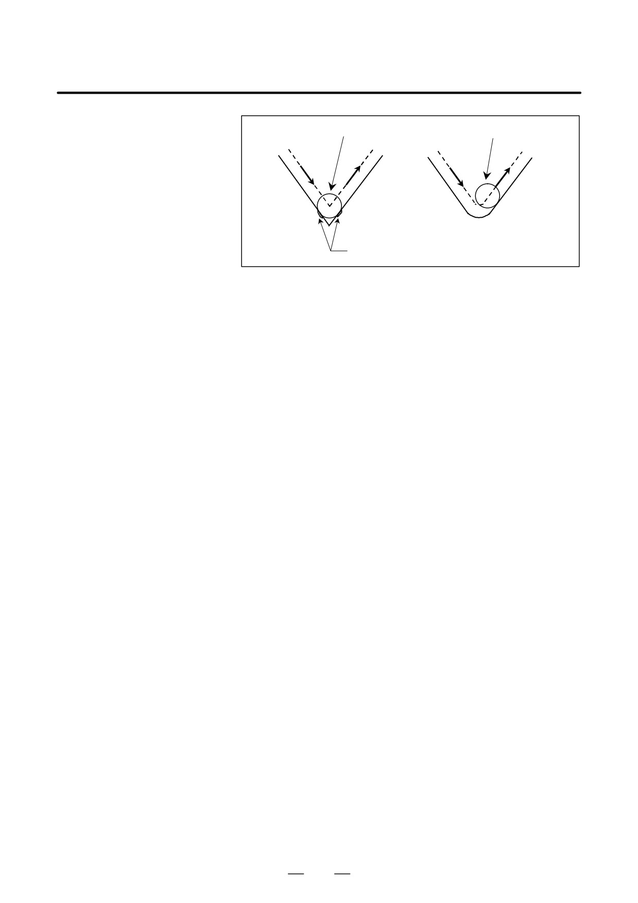
Overcut portion
Fig. 22.2 (i) Overcutting
D Setting the minimum
Set the same minimum input increment for an offset axis and linear axis
input increment for an
when cylindrical interpolation is performed.
offset axis (Y-axis)
D Workpiece radius
When specifying the radius of a workpiece, use the minimum input
specification
increment (with no decimal point) for the linear axis used in cylindrical
interpolation.
D Roll over function of
When the rotation axis using the roll over function is specified as the
rotation axis
rotation axis used for cylindrical interpolation, the roll over function is
disabled in cylindrical interpolation mode. The roll over function is
automatically enabled when cylindrical interpolation mode is released.
D Program restart
During a program restart, G07.1 for cylindrical interpolation mode cannot
be specified. PS/0175 occurs if G07.1 is specified.
Examples
D Example of cylindrical
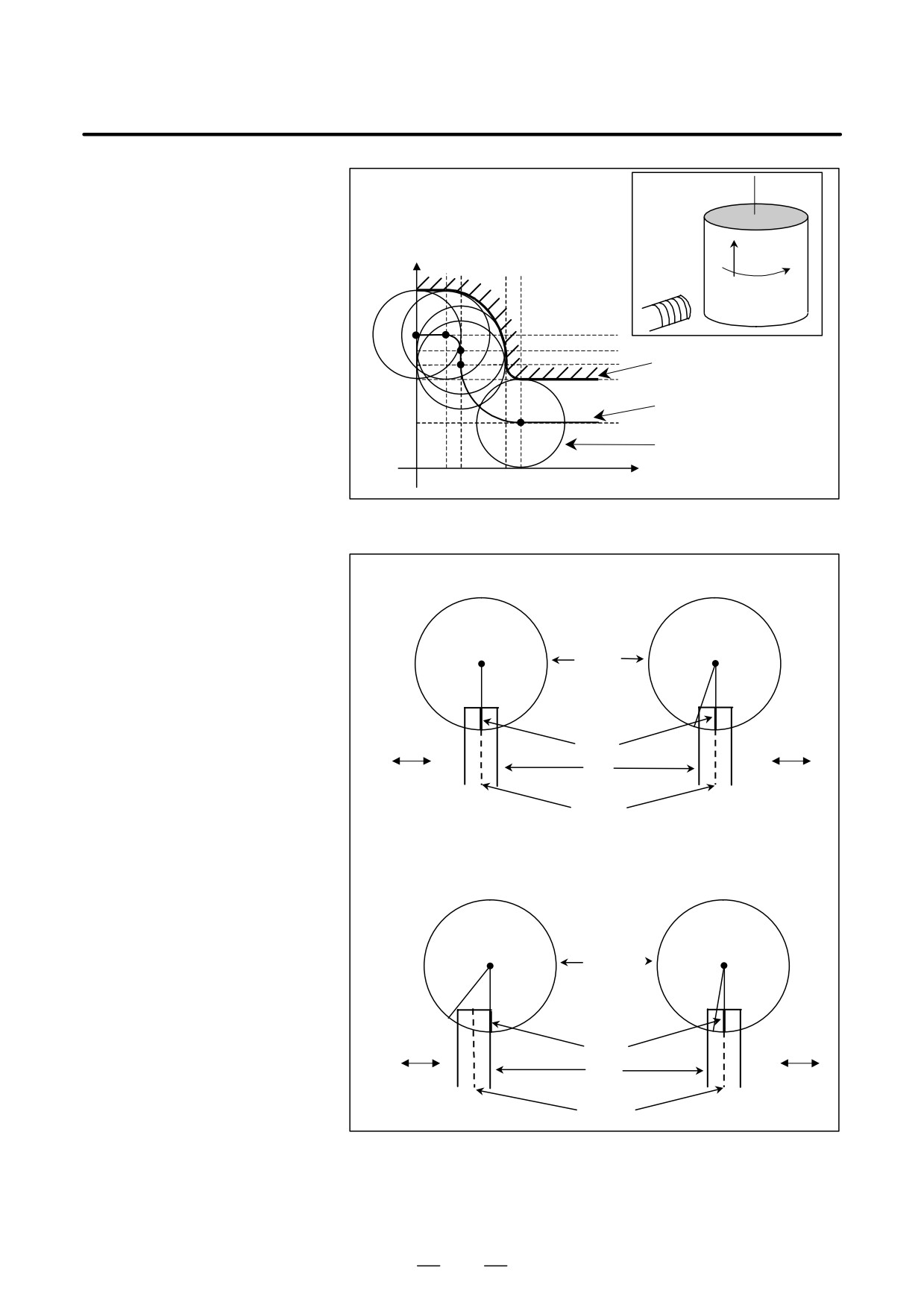
The sample program below indicates the positional relationships between
interpolation cutting
a workpiece and tool.
point compensation
O0001(CYLINDRICAL INTERPOLATION1) ;
N01 G00 G90 Z100.0 C0 ;
N02 G01 G91 G19 Z0 C0 ;
N03 G07.1 C57299 ;
N04 G01 G42 G90 Z120.0 D01 F250. ; - - - (1)
N05 C20.0 ;
- - - (2)
N06 G02 Z110.0 C60.0 R10.0 ;
- - - (3)
N07 G01 Z100.0 ;
- - - (4)
N08 G03 Z60.0 C70.0 R40.0 ;
- - - (5)
:
M30 ;
640
B-63534EN/02
PROGRAMMING
22. RISC PROCESSOR
Z-axis
Z-axis
(mm)
C-axis on the
120
Tool
Cylindrical
(1)
(2)
(3)
surface
(4)
90
80
70
Programmed path
60
Tool center path
30
(5)
Tool
C-axis on the Cylindrical surface
20 30
60 70
(deg)
Fig. 22.2 (j) Path of Sample Program for Cylindrical Interpolation Cutting
Point Compensation
Positional relationship between the
Positional relationship between
workpiece and tool of (1)
the workpiece and tool of (2)
Rotaion
Workpiece
Rotaion
Cutting
0°
0°
20°
surface
Tool
Y-axis
Y-axis
Tool
center
Positional relationship between the
Positional relationship between
workpiece and tool of (3) and (4)
the workpiece and tool of (5)
Rotaion
Workpiece
Rotaion
20°
Cutting
60°
60°70°
surface
Tool
Y-axis
Y-axis
Tool
center
Fig. 22.2 (k) Positional Relationships between Workpiece and Tool of
Sample Program
The cutting surfaces in the rotation axis direction in (3) and (4) are the
same, even when the cutter compensation is changed.
641

22. RISC PROCESSOR
PROGRAMMING
B-63534EN/02
Alarm
Number
Message
Contents
0015
TOO MANY AXES COMMANDED
A move command was specified for more axes than can be
controlled by simultaneous axis control.
Either add on the simultaneous axis control extension op-
tion, or divide the number of programmed move axes into
two blocks.
0175
ILLEGAL G107 COMMAND
An axis which cannot perform cylindrical interpolation was
specified.
More than one axis was specified in a G07.1 block. An at-
tempt was made to cancel cylindrical interpolation for an
axis that was not in the cylindrical interpolation mode.
For the cylindrical interpolation axis, set not “0” but one of
5, 6 or 7 (parallel axis specification) to parameter No. 1022
to instruct the arc with axis of rotation (ROT parameter No.
1006#1 is set to “1” and parameter No. 1260 is set) ON.
0176
IMPROPER G-CODE IN G107
A G code was specified that cannot be specified in the cy-
lindrical interpolation mode.
This alarm also is generated when an 01 group G code
was in the G00 mode or code G00 was instructed.
Cancel the cylindrical interpolation mode before instructing
code G00.
642
B-63534EN/02
PROGRAMMING
22. RISC PROCESSOR
22.3
TOOL CENTER
POINT CONTROL
General
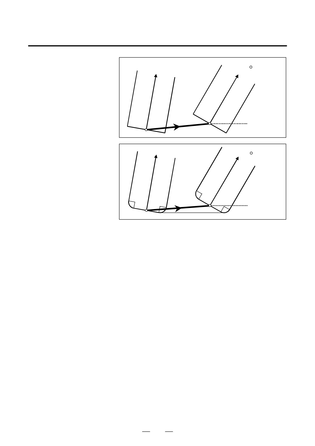
On a five-axis machine having two rotation axes that turn a tool, tool
length compensation can be performed momentarily even in the middle
of a block.
This tool length compensation is classified into one of two types based
on the programming method. In the explanation of this function, the two
rotation axes are assumed to be the B- and C-axes.
(1) Type 1
The rotation axis position (B, C) is specified.
The CNC applies tool length compensation according to the
compensation amount along the tool axis whose orientation is
calculated from the specified rotation axis position. This means that
compensation is performed by moving the three linear axes.
(2) Type 2
The tool axis orientation (I, J, K) is specified.
The CNC controls the two rotation axes so that the tool is oriented as
specified, and performs tool length compensation in tool axis
direction according to the compensation amount. This means that
compensation is performed by moving the two rotation axes and three
linear axes.
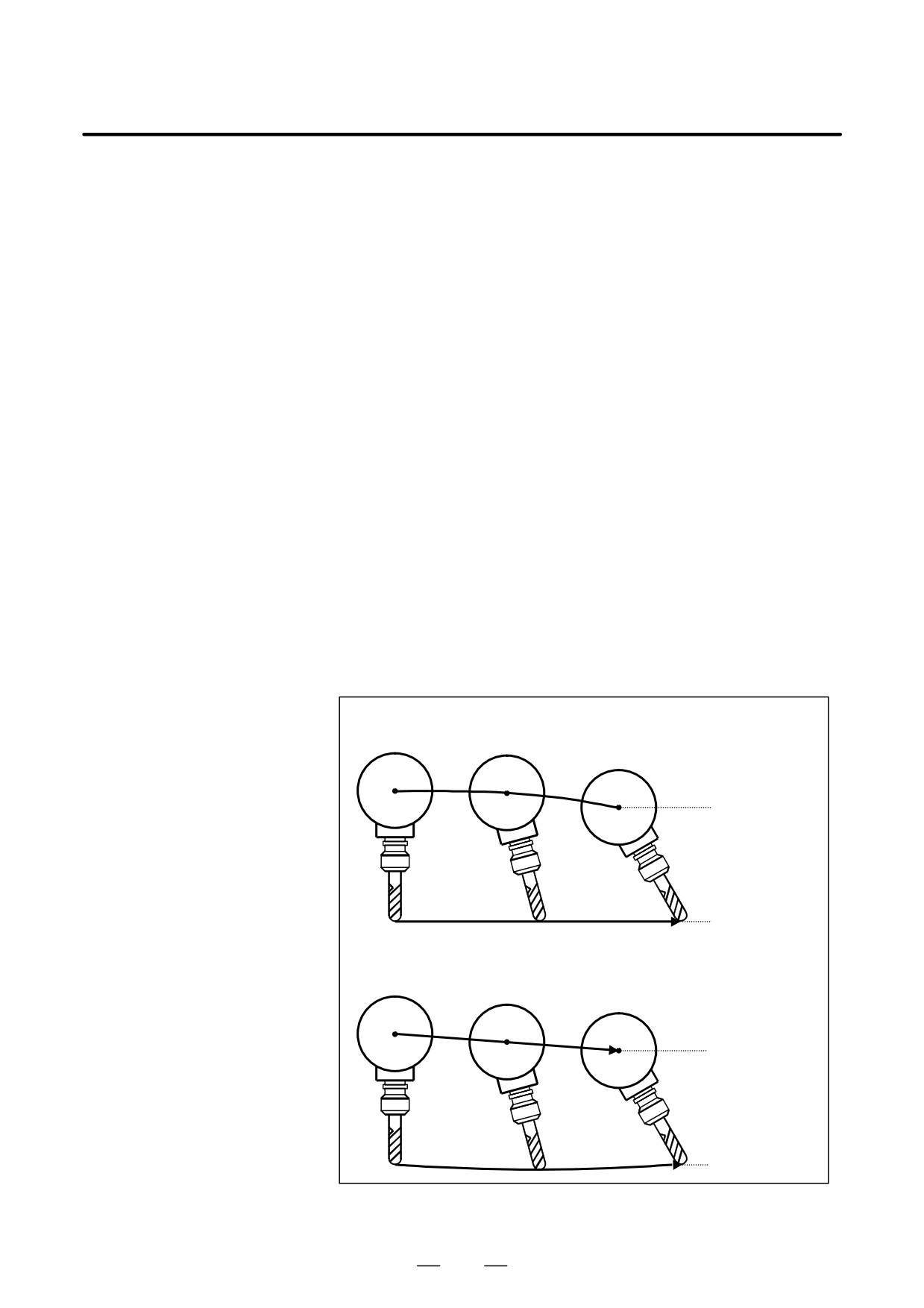
Tool center point control (type 1) differs from tool length compensation
in tool axis direction as shown below:
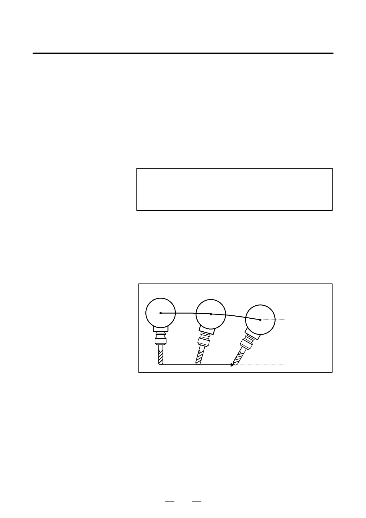
Pivot tool length compensation (type 1)
The path of the tool tip center is linear as specified.
Tool pivot point
=interpolation
path
(not linear)
Tool tip center path
(linear)
Tool length compensation along the tool axis
The path of the tool tip center is not linear.
Tool pivot point
= interpolation path
(linear)
Tool tip center path
(not linear)
Fig. 22.3 (a) Difference between Tool Center Point Control and Tool
Length Compensation in Tool Axis Direction
643

22. RISC PROCESSOR
PROGRAMMING
B-63534EN/02
NOTE
The length from the tool tip to tool pivot point must equal the
sum of the tool length compensation amount and tool holder
offset value.
Format
D Specifying tool center
point control (type 1)
G43.4 H_;
H
: Offset number
D Specifying tool center
point control (type 2)
G43.5 I_ J_ K_ H_ Q_;
I,J,K
: Tool axis orientation
H
: Offset number
Q
: Tool inclination angle (degrees)
NOTE
1
When I, J, and K are all omitted from a block, the
compensation vector in the previous block is used.
2
When any of I, J, and K is omitted, the omitted I, J, or K is
assumed to be 0.
3
Movement of the rotation axes is controlled by shortcut
control so that the amount of movement does not exceed
180_.
D Canceling tool center
point control
G49 ;
Description
D Specification of tool
The tool compensation vector changes in the following cases:
center point control
Type 1 : The offset value is changed, or the rotation axis position (B,
C) is specified.
Type 2 : The offset value is changed, or the tool axis orientation (I, J,
K) is specified.
As the tool compensation vector changes, movement is performed along
the X-, Y-, and Z-axes by an amount equal to the change. The time at
which the tool compensation vector is calculated is as follows:
Tool center point control : Calculated momentarily even in the middle
of a block.
Tool length compensation in tool axis direction: Calculated only at the
end point of a block.
644
B-63534EN/02
PROGRAMMING
22. RISC PROCESSOR
When only the rotation axis position is specified in tool center point
control (type 1) mode, and when only I, J, and K are specified in tool
center point control (type 2) mode, the tool tip center position remains
unchanged before and after the specification.
(Also, while the rotation
axes are being moved, the tool tip center does not move.)
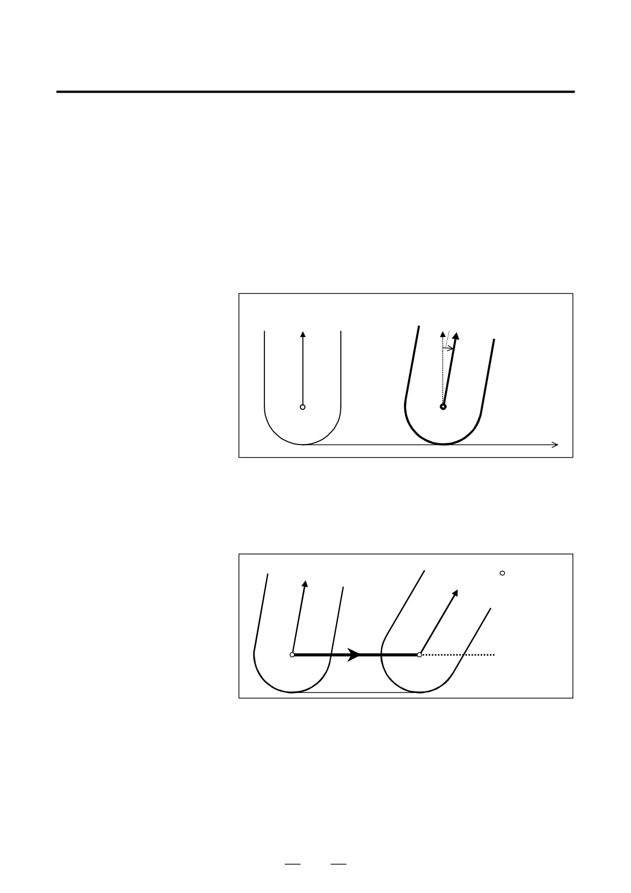
D Inclination of the tool
For tool center point control (type 2), the inclination angle of the tool can
be specified with address Q of G43.5. The inclination angle of the tool
is the difference in the angle between the tool orientation specified by (I,
J, K) and the tool orientation set for actual machining.
If the tool orientation specified by (I, J, K) matches the tool orientation
set for actual machining, Q need not be specified.
Tool orientation specified by (I,J,K)
Tool orientation during actual machining
Inclination angle of the tool
Machining direction
Example: For machining with the tool tilted toward the machining
direction by 2 degrees, specify the following:
G43.5 I_ J_ K_ H_ Q2.0
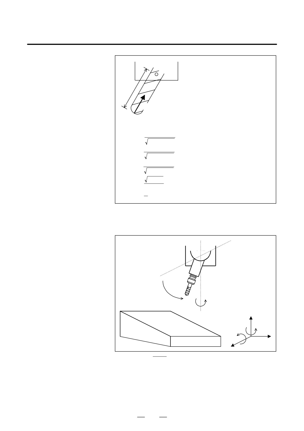
D Programmed point
In programming, the position of the tool tip center is specified.
Ball-end mill
Tool tip center
Programmed path
645
22. RISC PROCESSOR
PROGRAMMING
B-63534EN/02
Flat-end mill
Tool tip center
Programmed path
Corner-radius-endmill
Tool tip center
Programmed path
D Linear interpolation
When linear interpolation (G01) is specified in tool center point control
(G01)
mode, the feedrate is controlled so that the tool tip center moves at a
specified feedrate.
D Specification of rotation
axes
(1) Type 1
When only the rotation axes are specified in tool center point control
(type 1) mode, the feedrate of the rotation axes is set to the maximum
cutting feedrate (parameter No. 1422 or No.1430 or No.1432).
(2) Type 2
In tool center point control (type 2) mode, the rotation axes cannot be
specified. If the rotation axes are specified, alarm (5421) occurs.
646
B-63534EN/02
PROGRAMMING
22. RISC PROCESSOR
D Positioning (G00)
NOTE
1
Set the following parameters:
(1)Bit 1 (LRP) of parameter No.1401 = 1: Linear-type rapid
traverse
(2)Bit 5 (FRP) of parameter No.19501 = 1: Acceleration/
deceleration before interpolation is used in rapid traverse
(3) Parameter No.1620: Time constant used for acceleration/
deceleration for rapid traverse
(4)Parameter No.1621: Time constant T2 used for bell-
shaped acceleration/deceleration for rapid traverse
2
If the above settings are not made, or if look-ahead
acceleration/deceleration before interpolation is not valid,
axis movement may be performed at a higher feedrate than
the rapid traverse rate.
D Operation at start and
cancellation
(1) Type 1
When tool center point control (type 1) starts (G43.4H_) and when it
is canceled (G49), the CNC calculates the compensation vector only
at the end of the block.
(2) Type 2
When tool center point control (type 2) starts (G43.5H_) and when it
is canceled (G49), the CNC calculates the compensation vector only
at the end of the block.
D Operation of tool center
The following items are the same as for tool length compensation in tool
point control (type 1)
axis direction:
- Machine configuration example and equation for rotation axis
calculation
- Tool holder offset
- Specification of angular displacement in a parameter
- Zero-point compensation for the rotation axes
- Rotation axis offset
D Operation of tool center
The following item is the same as for tool length compensation in tool axis
point control (type 2)
direction :
- Tool holder offset
Positioning(G00) and linear interpolation(G01) is made on all five axes
simultaneously to the position (x, y, z, b, c) calculated as shown below.,
647
22. RISC PROCESSOR
PROGRAMMING
B-63534EN/02
x, y,z
: Tool center position
(x, y
,z
)
b,
c
: Rotation axis position
X,Y,Z
: tip position
(programmedposition)
l
I,
J,
K
: Tool axis direction
l
: Tool offset value
(I,J
,K
)
All positions are represented by absolute
coordinates.
(X,Y
,Z
)
I
x
=
X
+
l
2
2
I
+
J
2 +
K
J
y
=Y
+
l
2
2
I
+
J
2 +
K
K
z
=
Z
+
l
2
2
I
+
J
2 +
K
2
2
1
I
+
J
b
=
tan−
K
1
J
c
=
tan−
I
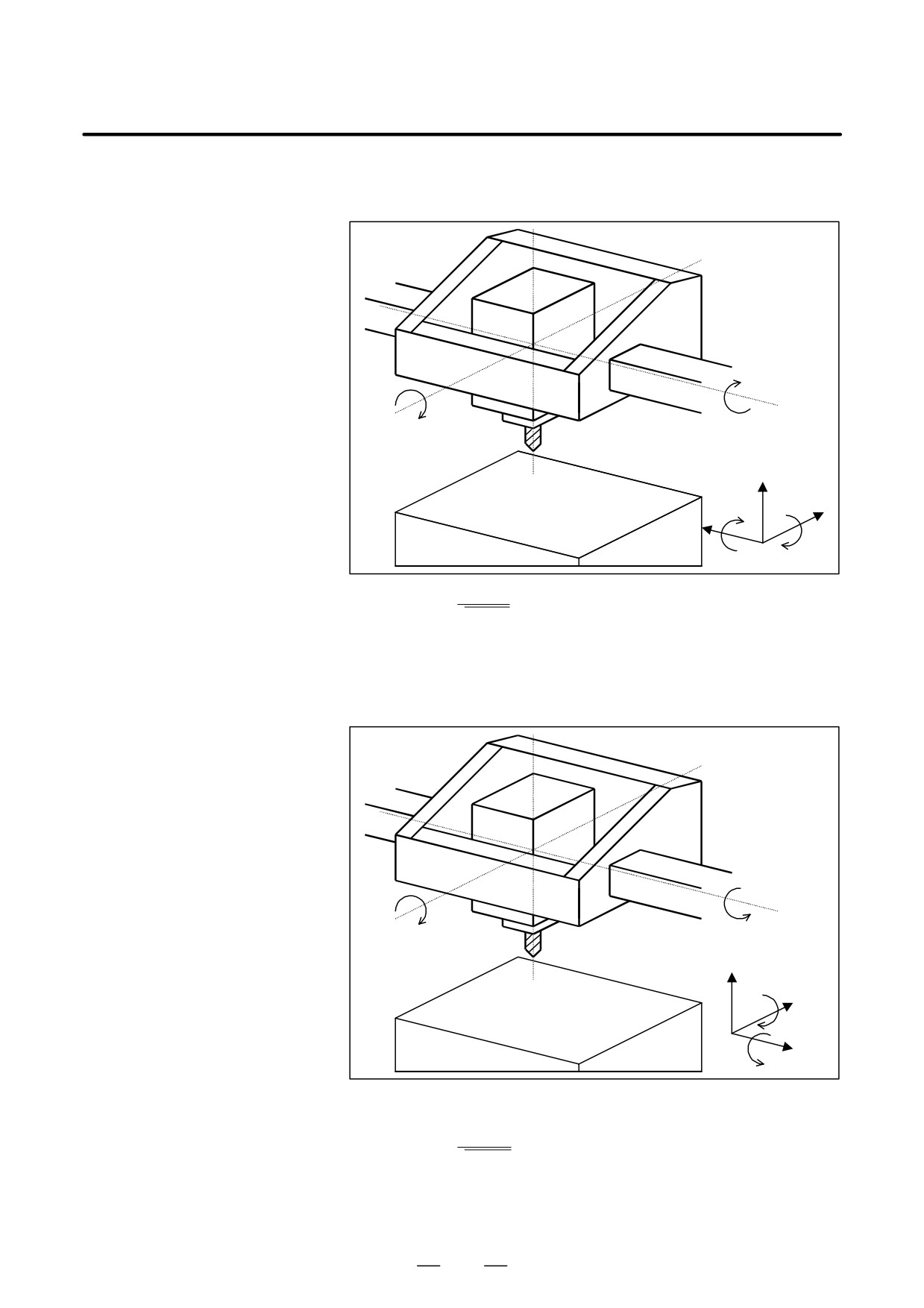
D Example of machine
configuration and
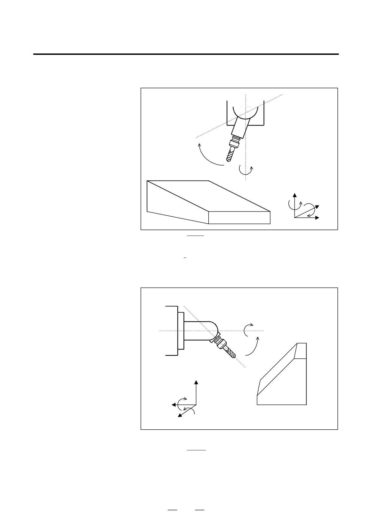
(1) When the rotation axes are the A- and C-axes, and the tool axis is the
expression for rotation
Z-axis
axis calculation
A
C
Z
Workpiece
C
A
Y
X
Ǹ
2
I2 ) J
a + tan*1
K
I
c + tan*1
-J
648
B-63534EN/02
PROGRAMMING
22. RISC PROCESSOR
(2) When the rotation axes are the B- and C-axes, and the tool axis is the
Z-axis
B
C
Z
C
Workpiece
B
Y
X
Ǹ
2
I2 ) J
b + tan*1
K
c + tan*1J
I
(3) When the rotation axes are the A- and B-axes, and the tool axis is the
X-axis
A
B
Z
Workpiece
A
X
B
Y
J
a + tan*1
-K
Ǹ
2
J2 ) K
b + tan*1
I
649
22. RISC PROCESSOR
PROGRAMMING
B-63534EN/02
(4) When the rotation axes are the A- and B-axes, and the tool axis is the
Z-axis (master axis : B-axis)
B
A
Z
B
X
Workpiece
Y
A
*J
a + tan*1
ǸI2 ) K2
I
b + tan*1
K
(5) When the rotation axes are the A- and B-axes, and the tool axis is the
Z-axis (master axis : A-axis)
A
B
Z
Y
B
Workpiece
X
A
a + tan*1-J
K
I
b + tan*1
ǸJ2 ) K2
D Tool life management
When tool life management is used, the tool length compensation amount
of the tool used is used for tool center point control.
650
B-63534EN/02
PROGRAMMING
22. RISC PROCESSOR
D Three-dimensional
Tool center point control and three-dimensional cutter compensation can
cutter compensation
be used at the same time.
Three-dimensional cutter compensation is applied to a specified tool tip
point.
Three-dimensional cutter compensation, however, is not
performed momentarily in the middle of a block; it is performed only at
the end of a block.
D Three-dimensional
When tool center point control (type 2) is used during three-dimensional
coordinate conversion
coordinate conversion, the tool axis orientation (I, J, K) is also subjected
to three-dimensional coordinate conversion.
D Rotation axis rollover
NOTE
Whenever using tool center point control (type 2), set bit 2
(ROAx) of parameter No. 1008 to 1 to perform rotation axis
rollover.
Restrictions
D Look-ahead
When using tool center point control, also use look-ahead acceleration/
acceleration/deceleration
deceleration before interpolation. If look-ahead acceleration/deceleration
before interpolation
before interpolation is not used, the feedrate may exceed the maximum
cutting feedrate as a result of tool center point control, which will cause
alarm P/S5422 to be issued.
Example:
Interpolation path
Tool tip center path
In the above example, the feedrate is controlled so that the tool tip center
moves at a specified feedrate. As a result, a higher feedrate than the
specified feedrate is detected on the interpolation path. In such a case, if
look-ahead acceleration/deceleration before interpolation is used, the
feedrate is clamped so that the feedrate on the interpolation path does not
exceed the maximum cutting feedrate. If look-ahead acceleration/
deceleration before interpolation is not used, the feedrate on the
interpolation path may become higher than the maximum cutting
feedrate, resulting in alarm P/S5422 being issued.
651
22. RISC PROCESSOR
PROGRAMMING
B-63534EN/02
D Functions resulting in
When the following functions are used in tool center point control mode,
the same operation as
the same operation as tool length compensation in tool axis direction
tool length
results:
compensation in tool
- Specification of an axis not related to tool center point control
axis direction
- The following G functions of group 01:
Circular interpolation, helical interpolation (G02, G03)
Involute interpolation (G2.2, G3.2)
Three-dimensional circular interpolation (G2.4, G3.4)
- Inverse time feed (G93)
D Restriction of commands
The following functions can be used but the state can not be changed in
tool center point control mode.
S Inch/metric conversion (An alarm(P/S5000) is issued if the state is
changed by G20 or G21)
S Mirror image (Do not change the state of the signal).
S Tool life management function
The tool length compensation use the amount of the tool specified by
tool life management function. The command for the tool life
management function have to command before tool axis direction tool
length compensation mode.
S F1 digit feed (Feedrate can not be changed by using the manual pulse
generator.)
D Unavailable commands
The following commands can not be used in tool center point control
mode. The alarm is issued if the function was used.
S
Custom macro
S
Exponential interpolation
-G02.3,G03.3
S
Dwell
-G04
S
High Speed Cutting Function relation
-G05
(G05P10000 and G05P0 are excluded)
S
AI contour control
-G05.1Q1,G5.1Q0
S
Hypothetical axis interpolation
-G07
S
Cylindrical interpolation
-G07.1
S
Advanced preview control
-G08
(Please use AI High Precision Contour Control)
S
Polar coordinate interpolation
-G12.1,G13.1
S
Polar coordinate command
-G15,G16
S
Reference position return check
-G27
S
Reference point return
-G28
S
2nd. Reference point return
-G30
S
3rd/4th reference point return
-G30
S
Skip
-G31
S
Thread cutting
-G33
S
Automatic tool length measurement
-G37
S
Normal direction control
-G40.1,G41.1,G42.1
S
Cutter compensation B
-G41,G42,G39
(Cutter compensation C is available)
652
B-63534EN/02
PROGRAMMING
22. RISC PROCESSOR
S
3-dimensional tool compensation
-G41
S
Wheel wear compensation
-G41
S
Tool offset
-G45,G46,G47,G48
S
Programmable mirror image
-G50.1,G51.1
S
Local coordinate system
-G52
S
Machine coordinate system
-G53
S
Single direction positioning
-G60
S
Automatic corner override
-G62
S
Tapping mode
-G63
S
Macro call
-G65,G66,G67
(SubProgram call is available)
S
Figure copying
-G72.1,G72.2
S
Canned cycle
-G73-G70,G80,G81-G89,
G98,G99
S
Simple electric gear box
-G80,G81
S
Functions for hobbing machine
-G80,G81
S
External operation function
-G81
S
Chopping function
-G81.1
S
Small hole peck drilling cycle
-G83
S
Setting a workpiece coordinate
-G92
system
S
Workpiece coordinate system
-G92.1
preset
S
Feed per revolution
-G95
S
Constant surface speed control
-G96,G97
S
Infeed control
-G160,G161
S
Workpiece coordinate system
-G54 to G59, G54.1
selection
S
M,S,T and B functions with motion command
S
Conical / spiral interpolation
In tool center point control mode, the functions listed below cannot be
used.
If these functions are used, the compensation vector of the previous block
is used as is.
- The following G functions of group 01:
S Spline interpolation (G06.1)
S Smooth interpolation (G05.1 Q2)
S NURBS interpolation (G06.2)
In the mode for this function, the following functions cannot be used, The
D Unavailable functions
warning message is displayed on the screen when the following functions
are used. :
S MDI operation
653

22.
RISC PROCESSOR
PROGRAMMING
B-63534EN/02
In the mode for this function, the following functions cannot be used, The
alarm(P/S5196) is issued when the following functions are used. :
- Manual interruption operation
- Tool retract and recover
The following functions can not be used in tool center point control mode.
S Flexible synchronous control
S Sequence number comparison and stop
It is not possible to stop by the sequence number in tool center point
control mode.
S Index table indexing
S Retrace function
Do not use retrace function in the program which uses tool center
point control mode.
S Rotary axis control
S Gentle curve normal direction control
S Tool life management
Tool life value is counted in tool center point control mode.
However , do not use the command related to the tool life
management function.
S Macro executor (Execution macro)
S Manual handle interruption
S External deceleration ( external deceleration is not effected )
D Other Restrictions
When the following function is used, tool center point control cannot be
used.
S Angular axis control
S Arbitary angular axis control
The limitation may be attached about the combination of the NC
instructions occasionaly.
Refer the description of the each functions.
Alarms
Number
Message
Description
5425
ILLEGAL OFFSET VAL-
The offset number is illegal.
UE
5420
ILLEGAL PARAMETER
There is an illegal parameter relating to
IN G43.4/G43.5
tool center point control.
5421
ILLEGAL COMMAND
Rotation axes are specified in tool cen-
IN G43.4/G43.5
ter point control (type 2).
5422
EXCESS VELOCITY IN
As a result of tool center point control,
G43.4/G43.5
the feedrate along an axis exceeds the
maximum cutting feedrate.
654
B-63534EN/02
PROGRAMMING
22. RISC PROCESSOR
22.4
TOOL AXIS
COMPENSATION IN
TOOL AXIS
DIRECTION
General
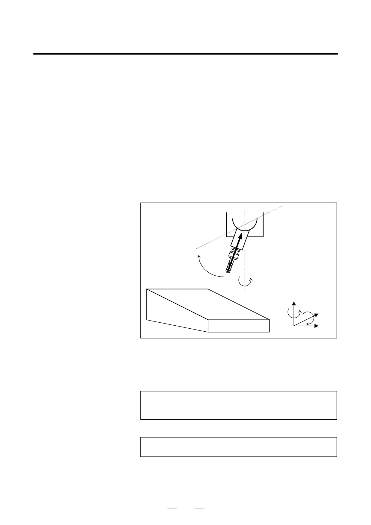
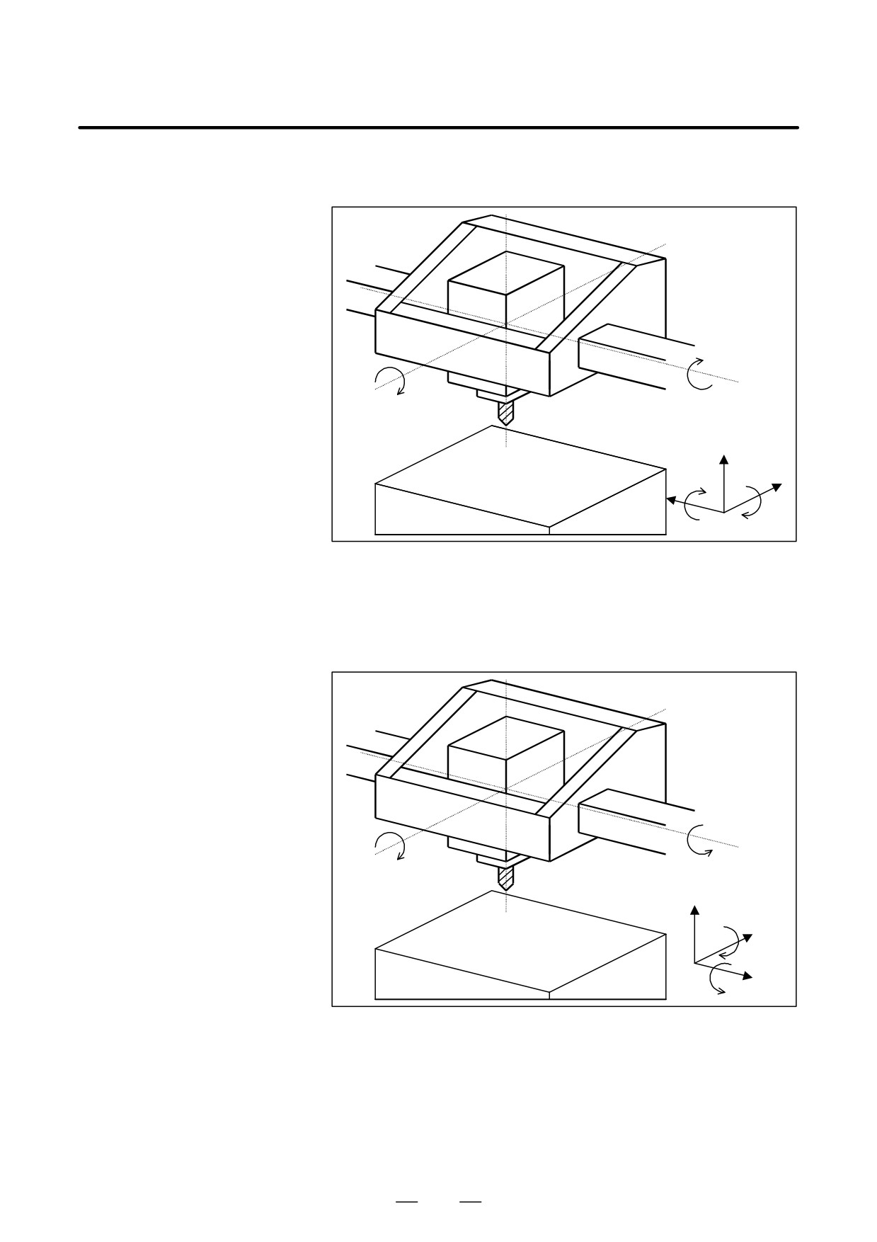
When a 5-axis machine that has two axes for rotating the tool is used, tool
length compensation can be performed in a specified tool axis direction
on a rotation axis. When a rotation axis is specified in tool length
compensation in tool axis direction mode, tool length compensation is
applied in a specified tool axis direction on the rotation axis by the
compensation value specified in the H code. That is, movement is made
along the three linear axes (Xp, Yp, Zp).
Unless otherwise noted in the explanation of this function, the two
rotation axes are assumed to be the B-axis and C-axis.
Tool axis direction
B
C
Z
Workpiece
C
B
Y
X
Fig. 22.4 (a) Tool Length Compensation in Tool Axis Direction
Format
D Command for tool length
compensation in tool
axis direction
G43.1 Hn ;
n : Offset number
D Command for
cancellation of tool
length compensation in
G49 ;
tool axis direction
655
22. RISC PROCESSOR
PROGRAMMING
B-63534EN/02
Explanations
D Command for tool length
The tool compensation vector changes as the offset value changes or
compensation in tool
movement is made on a rotation axis. When the tool compensation vector
axis direction
changes, movement is made according to the change value along the
X-axis, Y-axis, and Z-axis.
When the command specifies movement on a rotation axis only, the
position of the tool tip is the same both before and after execution of the
command.
(During rotation axis movement, however, the tool tip
moves.)
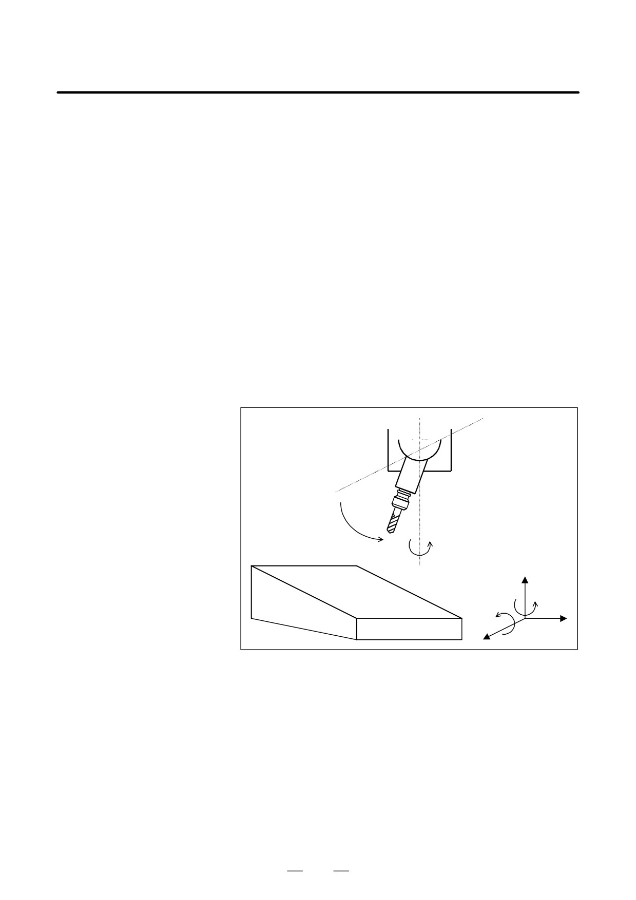
D Examples of machine
Let Vx, Vy, Vz, Lc, a, b, and c be as follows :
configuration and
Vx,Vy,Vz
: Tool compensation vectors along the X-axis, Y-axis,
rotation axis calculation
and Z-axis
formats
Lc
: Offset value
a,b,c
: Absolute coordinates on the A-axis, B-axis and
C-axis
Then, the tool compensation vector on each axis in each machine
configuration is indicated below.
(1) A-axis and C-axis, with the tool axis on the Z-axis
A
C
Z
Workpiece
C
A
Y
X
Vx = Lc * sin(a) * sin(c)
Vy = -Lc * sin(a) * cos(c)
Vz = Lc * cos(a)
656
B-63534EN/02
PROGRAMMING
22. RISC PROCESSOR
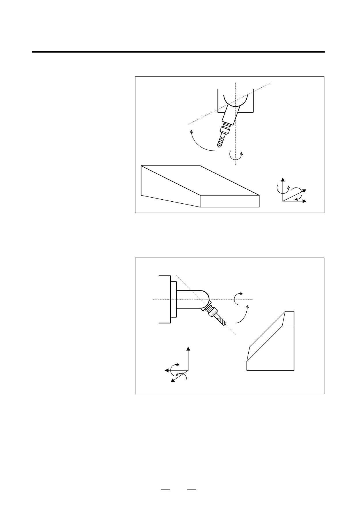
(2) B-axis and C-axis, with the tool axis on the Z-axis
B
C
Z
Workpiece
C
B
Y
X
Vx = Lc * sin(b) * cos(c)
Vy = Lc * sin(b) * sin(c)
Vz = Lc * cos(b)
(3) A-axis and B-axis, with the tool axis on the X-axis
A
B
Z
Workpiece
A
X
B
Y
Vx = Lc * cos(b)
Vy = Lc * sin(b) * sin(a)
Vz = -Lc * sin(b) * cos(a)
657
22. RISC PROCESSOR
PROGRAMMING
B-63534EN/02
(4) A-axis and B-axis, with the tool axis on the Z-axis, and the B-axis
used as the master
B
A
Z
B
X
Workpiece
Y
A
Vx = Lc * cos(a) * sin(b)
Vy = -Lc * sin(a)
Vz = Lc * cos(a) * cos(b)
(5) A-axis and B-axis, with the tool axis on the Z-axis, and the A-axis
used as the master
A
B
Z
Y
B
Workpiece
X
A
Vx = Lc * sin(b)
Vy = -Lc * sin(a) * cos(b)
Vz = Lc * cos(a) * cos(b)
658
B-63534EN/02
PROGRAMMING
22. RISC PROCESSOR
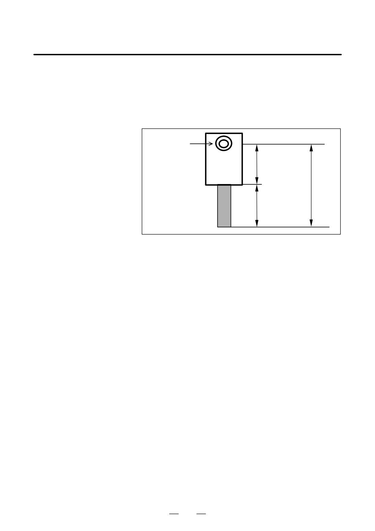
D Tool holder offset
The machine-specific length from the rotation center of the tool rotation
axes (A- and B-axes, A- and C-axes, and B- and C-axes) to the tool
mounting position is referred to as the tool holder offset. Unlike a tool
length offset value, a tool holder offset value is set in parameter No.
19666. When tool length compensation in tool axis direction is applied,
the sum of the tool holder offset and tool length offset is handled as a tool
length for compensation calculation.
Rotation
center
Tool holder
offset
Tool
length
Tool length offset
Fig. 22.4 (b) Tool Holder Offset
D Parameter-based
A tool compensation vector is found from the coordinates on the rotation
rotation angle
axes for controlling the tool axis direction. However, the configuration
specification
of some machines is such that the tool axis is inclined using a fixed
attachment. In such a case, the rotation angles of the rotation axes can be
set using parameters.
Set bit 1 (RAP) of parameter No. 19650 to 1, and set the coordinates in
parameter No. 19658.
D Rotation axis origin
This function compensates for a slight shift of the rotation axis origin
compensation
caused, for example, by thermal displacement. Specify a compensation
value in parameter No. 19660.
When the tool axis is on the Z-axis, and the rotation axes are the B-axis
and C-axis, a compensation vector is calculated as follows :
Xp = Lc * sin(B-Bz) * cos(C-Cz)
Yp = Lc * sin(B-Bz) * sin(C-Cz)
Zp = Lc * cos(B-Bz)
Xp,Yp,Zp
: Compensation pulse on each axis after origin shift
compensation
Lc
: Offset value
B,C
: Machine position on B-axis and C-axis
Bz,Cz
: Origin compensation value on B-axis and C-axis
D Rotation axis offset
Set offsets relative to the rotation angles of the rotation axes in parameter
No. 19659. The compensation vector calculation formula is the same as
that used for rotation axis origin compensation, except that Bp and Cp are
changed to rotation axis offsets.
When rotation axis origin compensation and rotation offsetting are set at
the same time, both compensations are performed.
When the tool axis is on the Z-axis, and the rotation axes are the B-axis
and C-axis, compensation vector calculation is performed as follows :
659
22. RISC PROCESSOR
PROGRAMMING
B-63534EN/02
Xp = Lc * sin(B-(Bz+Bo)) * cos(C-(Cz+Co))
Yp = Lc * sin(B-(Bz+Bo)) * sin(C-(Cz+Co))
Zp = Lc * cos(B-(Bz+Bo))
Bz,Cz
: B-axis and C-axis origin compensation values
Bo,Co : B-axis and C-axis rotation axis offset values
D Control Point
Normally, the control point of tool length compensation in tool axis
Compensation of Tool
direction is the point of intersection of the centers of two rotation axes.
Length Compensation in
The machine coordinates also indicate this control point.
Tool Axis Direction
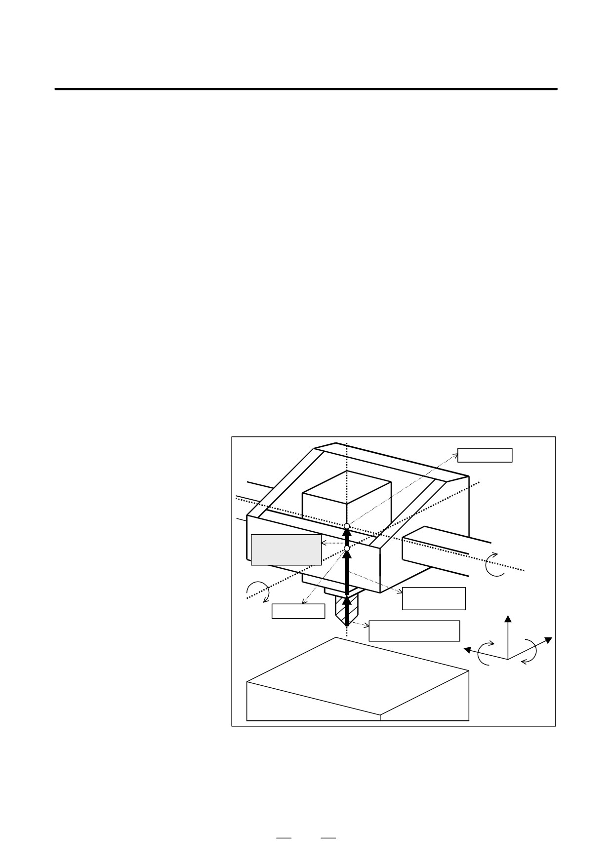
This section explains the compensation performed when the centers of the
two rotation axes do not intersect and also explains how to place the
control point at a convenient position on the machine.
Explanation
D Compensation of the
Compensation when the rotation centers of two rotation axes do not match
rotation centers of two
is performed.
rotation axes
The length from the tool mounting position to the first rotation axis center
is set as the tool holder offset value in parameter No. 19666.
The vector from the first rotation axis center to the second rotation axis
center is set as the rotation center compensation vector in parameter No.
19661. Since parameter No. 19661 is an axis type parameter, the
compensation amount for three axes (X, Y, and Z) can be set in this
parameter.
B axis center
Rotation center
compensation
B
vector
Tool holder
offset
A
Z
A axis center
Tool length
B
X
compensationamount
Y
A
Workpiece
Fig. 22.4 (c) Compensation of Rotation Centers of Two Rotation Axes
660

B-63534EN/02
PROGRAMMING
22. RISC PROCESSOR
According to the machine type, set the values listed in the following table:
Table 22.4 (a) Setting the Tool Holder Offset and Rotation Center
Compensation Vector
Machine type
Tool holder offset
Rotation center
Parameter No. 19666
compensation vector
Parameter No. 19661
(1)A- and C- axes.
Length from tool mounting
Vector from A-axis center
Tool axis is Z-
position to A-axis center
to C-axis center
axis.
(2)B- and C-axes.
Length from tool mounting
Vector from B-axis center
Tool axis is Z-
position to B-axis center
to C-axis center
axis.
(3)A- and B-axes.
Length from tool mounting
Vector from B-axis center
Tool axis is X-
position to B-axis center
to A-axis center
axis.
(4)A- and B-axes.
Length from tool mounting
Vector from A-axis center
Tool axis is Z-
position to A-axis center
to B-axis center
axis.
B-axis is master.
(5)A- and B-axes.
Length from tool mounting
Vector from B-axis center
Tool axis is
position to B-axis center
to A-axis center
Z-axis.
A-axis is master.
NOTE
When using the spindle center compensation described
below, set the length from the tool mounting position to the
spindle center as the tool holder offset.
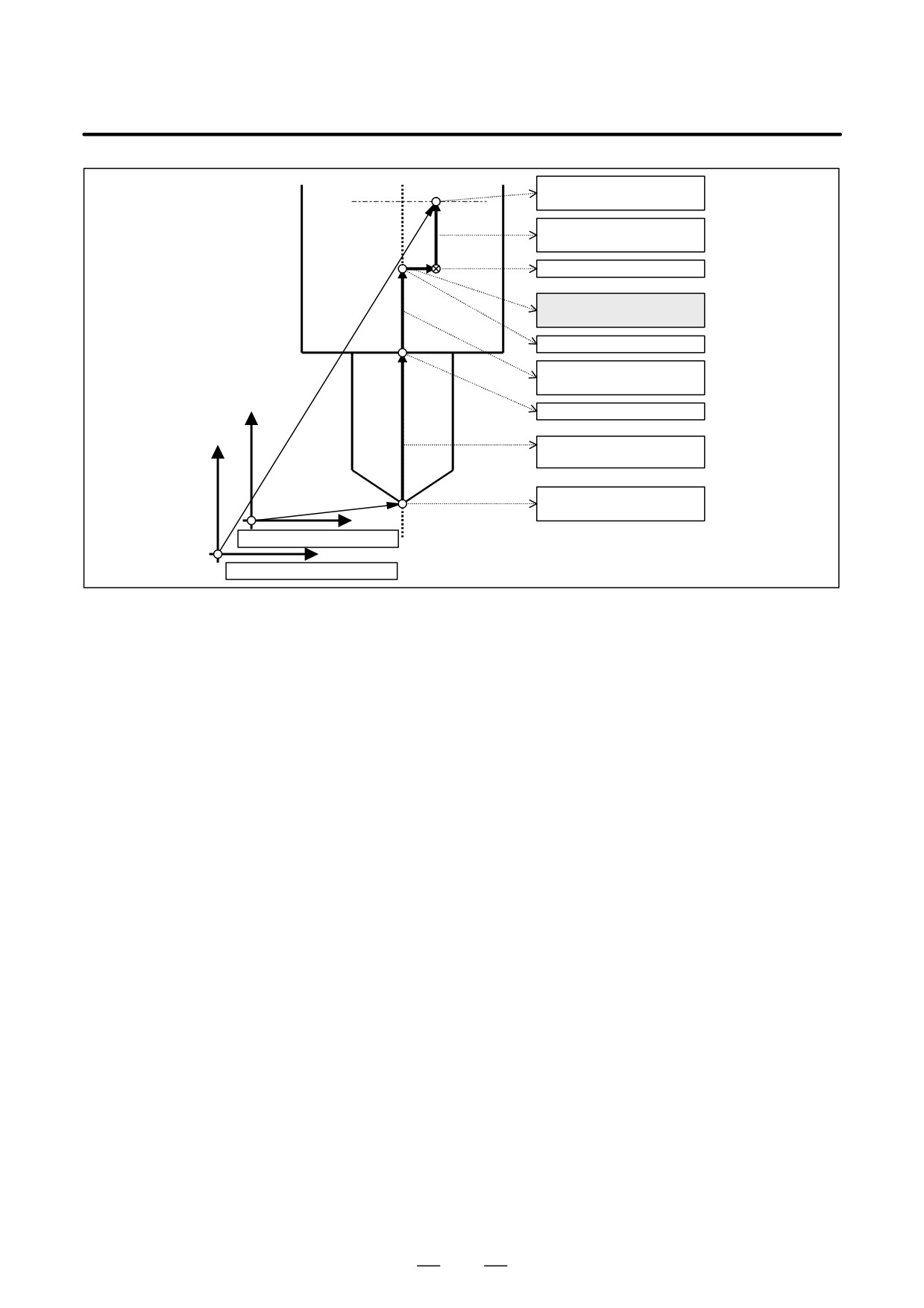
D Spindle center
Compensation of the spindle center is performed.The amount of spindle
Compensation
center compensation is set in parameter No. 19662. Since parameter No.
19662 is an axis type parameter, the compensation amount for three axes
(X, Y, and Z) can be set in this parameter.
661
22. RISC PROCESSOR
PROGRAMMING
B-63534EN/02
Second rotation axis
center (control point)
Rotation center compensation
vector parameter (No. 19661)
First rotation axis center
Spindle center compensation
vector parameter (No. 19662)
Spindle center
Tool holder offset
parameter (No. 19666)
Tool mounting position
Tool length
compensationamount
Tool tip
(programmedpoint)
Workpice coordinate origin
Machine coordinate origin
Fig. 22.4 (d) Spindle Center Compensation
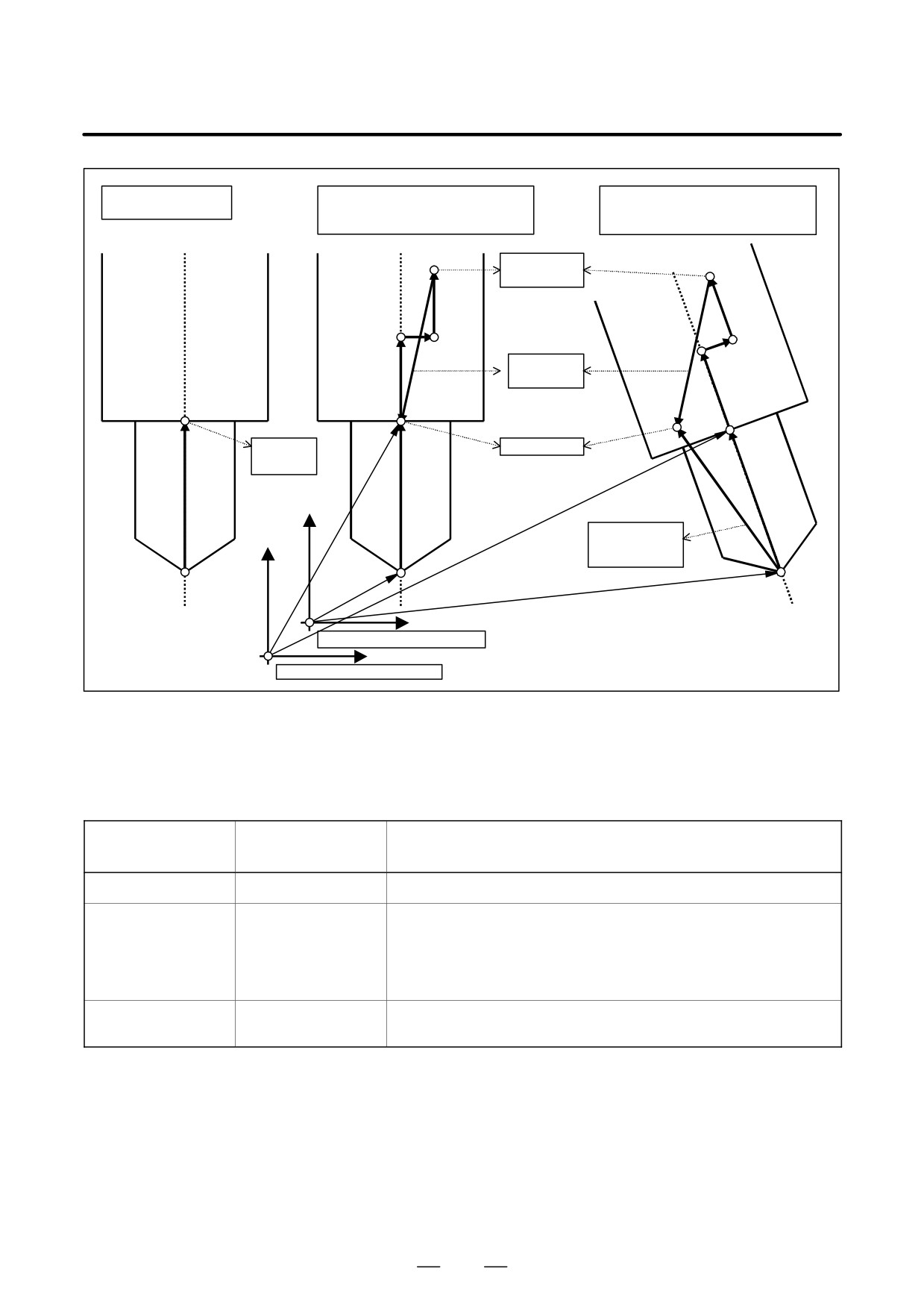
Conventionally, the center of a rotation axis was used as the control point.
Shifting the control point
The control point can now be shifted as shown in the figure below.
Then, when the rotation axis is at the 0-degree position also in tool length
compensation in tool axis direction (G43.1), the control point can be set
to the same position as that for ordinary tool length compensation (G43).
The control point here is indicated with machine coordinates.
When linear interpolation is specified, for example, this control point
moves linearly.
662
B-63534EN/02
PROGRAMMING
22. RISC PROCESSOR
Ordinary tool length
Tool length compensation in tool axis
Tool length compensation in tool axis
compensation (G43)
direction(G43.1) :
direction (G43.1) :
When tool is not tilted
When tool is tilted
Control point
before shift
Shift
vector
Control
Control point
point
Tool length
compensation
vector
Workpiece coordinate origin
Machine coordinate origin
Fig. 22.4 (e) Shift of the Control Point
The method of shifting the control point can be selected using the
following parameters:
Table 22.4 (b) Methods of Shifting the Control Point
Bit 5 (SVC) of
Bit 4 (SPR) of
Shift of control point
parameter No. 19665
parameter No. 19665
0
-
As in the conventional case, the control point is not shifted.
1
0
The control point is shifted, and the shift vector is calculated automati-
cally as follows:
- (rotation center compensation vector (parameter No. 19661))
+ spindle center compensation vector (parameter No. 19662))
+ tool holder offset along tool axis (parameter No. 19666))
1
1
The control point is shifted, and the shift vector is the vector set in pa-
rameter No. 19667.
D Equation for each
machine type
Vx, Vy, Vz : Tool length compensation vector
A, B, C
: Absolute coordinates of A-, B-, and C-axes
To
: Tool offset value
Ho
: Tool holder offset value
Jx, Jy, Jz
: Rotation center compensation vector
Cx, Cy, Cz : Spindle center compensation vector
Sx, Sy, Sz : Shift vector
663
22.
RISC PROCESSOR
PROGRAMMING
B-63534EN/02
Suppose the above. Then, the tool length compensation vector for each
axis is calculated depending on the machine type, as follows:
(1) A- and C-axes. The tool axis is the Z-axis.
Vx
cos C
* sin C
0
1
0
0
Cx
Jx
Sx
Vy
sin C
cos C
0
0
cos A
* sin A
Cy
Jy
ƪ
ƫ
+ƪ
ƫȡ
ƪ
ƫƪ
ƫ
)ƪ
ƫȣ
Syƫ
Vz
0
0
1
0 sin A cos A
To ) Ho ) Cz
Jz
Sz
Ȣ
Ȥ) ƪ
(2) B- and C-axes. The tool axis is the Z-axis.
Vx
cos C
* sin C
0
cos B
0
sin B
Cx
Jx
Sx
Vy
sin C
cos C
0
0
1
0
Cy
Jy
ƪ
ƫ
+ƪ
ƫȡ
ƪ
ƫƪ
ƫ
)ƪ
ƫȣ
Syƫ
Vz
0
0
1
* sin B 0 cos B
To ) Ho ) Cz
Jz
Sz
Ȣ
Ȥ) ƪ
(3) A- and B-axes. The tool axis is the X-axis.
Vx
1
0
0
cos B
0
sin B
To ) Ho ) Cx
Jx
Sx
Vy
0
cos A
* sin A
0
1
0
Cy
Jy
ƪ
ƫ
+ƪ
ƫȡ
ƪ
ƫƪ
ƫ
)ƪ
ƫȣ
Syƫ
Vz
0 sin A cos A
* sin B 0 cos B
Cz
Jz
Sz
Ȣ
Ȥ) ƪ
(4) A- and B-axes. The tool axis is the Z-axis, and the B-axis is the
master.
Vx
cos B
0
sin B
1
0
0
Cx
Jx
Sx
ƪ
Vy
ƫ
+ƪ
0
1
0
ƪ
0
cos A
* sin A
ƫƪ
Cy
ƫ
)ƪ
Jy
Syƫ
ƫȡ
ƫȣ
Vz
* sin B 0 cos B
0 sin A cos A
To ) Ho ) Cz
Jz
Sz
Ȣ
Ȥ) ƪ
(5) A- and B-axes. The tool axis is the Z-axis, and the A-axis is the
master.
Vx
1
0
0
cos B
0
sin B
Cx
Jx
Sx
ƪ
Vy
ƫ
+ƪ
0
cos A
* sin A
ƪ
0
1
0
ƫƪ
Cy
ƫ
)ƪ
Jy
Syƫ
ƫȡ
ƫȣ
Vz
0 sin A cos A
* sin B 0 cos B
To ) Ho ) Cz
Jz
Sz
Ȣ
Ȥ) ƪ
The shift vector (Sx, Sy, Sz) is calculated as follows:
(A) When bit 5 (SVC) of parameter No.19665 = 0, the vector is set to 0.
(B) When bit 5 (SVC) of parameter No.19665 = 1, and bit 4 (SPR) of
parameter No. 19665 = 0:
When the machine type is other than (3)
Sx
Cx ) Jx
Sy
ƪ
ƫ
+*ƪ
Cy ) Jy ƫ
Sz
Cz ) Jz ) Ho
When the machine type is (3)
Sx
Cx ) Jx ) Ho
Sy
ƪ
ƫ
+*ƪ
Cy ) Jy ƫ
Sz
Cz ) Jz
(C) When bit 5 (SVC) of parameter No.19665 = 1, and bit 4 (SPR) of
parameter No. 19665 = 1, the vector specified in parameter No. 19667
is set.
Restriction
D Limitation of Functions
In the mode for this function, the following functions can be used, but the
condition of each function cannot be changed
- Inch/metric conversion
The alarm is issued when the condition is changed by G20 or G21
command.
664
B-63534EN/02
PROGRAMMING
22. RISC PROCESSOR
– Mirror image
The condition of DI signal cannot be changed.
- Tool life management function
The tool length compensation use the amount of the tool specified by
tool life management function. The command for the tool life
management function have to command before tool axis direction tool
length compensation mode.
- One-digit F code feed
The feedrate cannot be changed by using manual pulse generator.
D Commands that cannot
In the mode for this function, the following commands cannot be used.
be specified
The alarm is issued when the following commands are orderd. :
-
Custom macro B
–
Exponentioal interpolation
-G02.3,G03.3
–
Dwell
-G04
–
Function concerning high-speed
-G05
machining
(exclude G05P10000 and 05P0)
-
AI precision control
-G05.1Q1,G5.1Q0
–
Hypothetical axis interpolation
-G07
–
Cylindrical interpolation
-G07.1
–
Advanced preview control
-G08
(Please use AI HPCC function)
-
Polar coordinate interpolation
-G12.1,G13.1
–
Polar coordinate command
-G15,G16
–
Reference position return check
-G27
–
Reference position return
-G28
–
2nd Reference position return
-G30
–
3rd/4th Reference position return
-G30
–
Skip
-G31
–
Threading
-G33
–
Automatic tool length measurement -G37
–
Normal direction control
-G40.1,G41.1,G42.1
–
Cutter compensation B
-G41,G42,G39
(Cutter compensation C is available)
-
3 dimensional cutter compensation
-G41
–
Wheel wear compensaton
-G41
–
Tool offset
-G45,G46,G47,G48
–
Programmable mirror image
-G50.1,G51.1
–
Local coordinate system
-G52
–
Machine coordinate system
-G53
–
Single direction positioning
-G60
–
Automatic corner override
-G62
–
Tapping mode
-G63
–
Macro call
-G65,G66,G67
(Sub program call is available)
665
22. RISC PROCESSOR
PROGRAMMING
B-63534EN/02
– Figure copy
-G72.1,G72.2
– Canned cycles
-G73-G79,G80,G81-G89,
G98,G99
- Electric gear box
-G80,G81
– Function for hobbing machine
-G80,G81
– External motion function
-G81
– Chopping
-G81.1
– Small-hole peck drilling cycle
-G83
– Changing workpiece coordinate system
-G92
- workpiece coordinate system preset -G92.1
- Feed per revolution
-G95
– Constant surface speed control
-G96,G97
– Infeed control
-G160,G161
– NURBS interpolation
-G06.2
– Workpiece coordinate system
-G54,G54.1,G55,G56,G57,
G58,G59
- M,S,T and B functions with motion command
D Function that cannot be
In the mode for this function, the following functions cannot be used, The
specified
warning message is displayed on the screen when the following functions
are used. :
- MDI intervention
In the mode for this function, the following functions cannot be used, The
alarm(P/S5196) is issued when the following functions are used. :
- Manual interruption operation
- Tool retract and recover
And , in the mode for this function, the following functions cannot be
used.
- Flexible synchronous control
- Sequence number comparison and stop
(The program is not stop at the specified sequence block in tool axis
direction tool length compensation mode.)
- Index table indexing
- Retrace function
Retrace function cannot be used by the program which uses tool axis
direction tool length compensation.
- Rotary axis control
- Gentle normal direction control
- Thc command for the tool life management function
(Tool life time is able to be counted in this mode, but the command for
the tool life management function cannot be used.)
- Macro executor ( Execution macro )
- Manual handle interruption operation
666

B-63534EN/02
PROGRAMMING
22. RISC PROCESSOR
– External deceleration
External decelaration is not available in this mode.
D Others
tool axis direction tool length compensation function cannot be used with
the following function.
- Angular axis control
- Arbitrary angular axis contol
The limitation attaches about the combination of other NC instructions
occasionally.
Please refer to the manual of the each function.
Alarms
Number
Message
Contents
5196
ILLEGAL AXIS OPERA-
A function which cannot be used during
TION
HPCC function ¡¡or 5-axis control func-
tion is being executed was commanded.
5435
PARAMETER OUT OF
Illegal parameter setting. (Set value is
RANGE (TLAC)
out of range.)
5436
PARAMTER SETTING
Illegal parameter setting. (axis of rota-
ERROR 1 (TLAC)
tion setting)
5437
PARAMETER SETTING
Illegal parameter setting (tool axis set-
ERROR 2 (TLAC)
ting)
667
22. RISC PROCESSOR
PROGRAMMING
B-63534EN/02
22.5
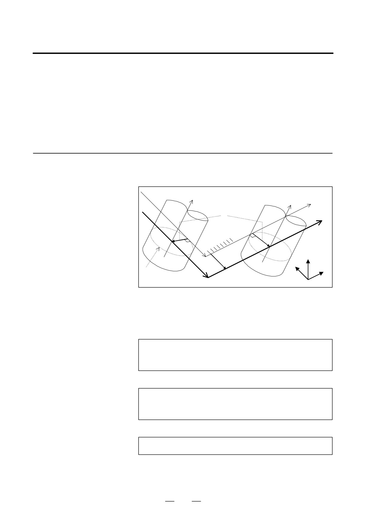
The 3-dimensional cutter compensation function is used with machines
that can control the direction of tool axis movement by using rotation axes
3-DIMENSIONAL
(such as the B- and C-axes). This function performs cutter compensation
CUTTER
by calculating a tool vector from the positions of the rotation axes, then
COMPENSATION
calculating a compensation vector in a plane (compensation plane) that
is perpendicular to the tool vector.
There are two types of cutter compensation : Tool side compensation and
leading edge compensation. Which is used depends on the type of
machining.
22.5.1
Tool side compensation is a type of cutter compensation that performs
3-dimensional compensation on a plane
(compensation plane)
Tool Side
perpendicular to a tool direction vector.
Compensation
Programmed tool path
Tool vector
(before compensation)
Cutter compensa-
tion vector
Tool center
path(after
compensa-
tion)
Z
Y
X
Compensation
Cutter
plane
compensation amount
Fig. 22.5.1 (a) Tool side compensation
Format
D Tool side
compensation(left)
G41.2 X_ Y_ Z_ D_ ;
If type C of cancellation operation is selected at start-up, never
specify a move command such as X_Y_Z_ in the G41.2 block.
D Tool side
compensation(right)
G42.2 X_ Y_ Z_ D_ ;
If type C of cancellation operation is selected at start-up, never
specify a move command such as X_Y_Z_ in the G42.2 block.
D Tool side offset cancel
G40 X_ Y_ Z_ ;
668
B-63534EN/02
PROGRAMMING
22. RISC PROCESSOR
Explanations
D Operation at
compensation start-up
and cancellation
(1) Type A
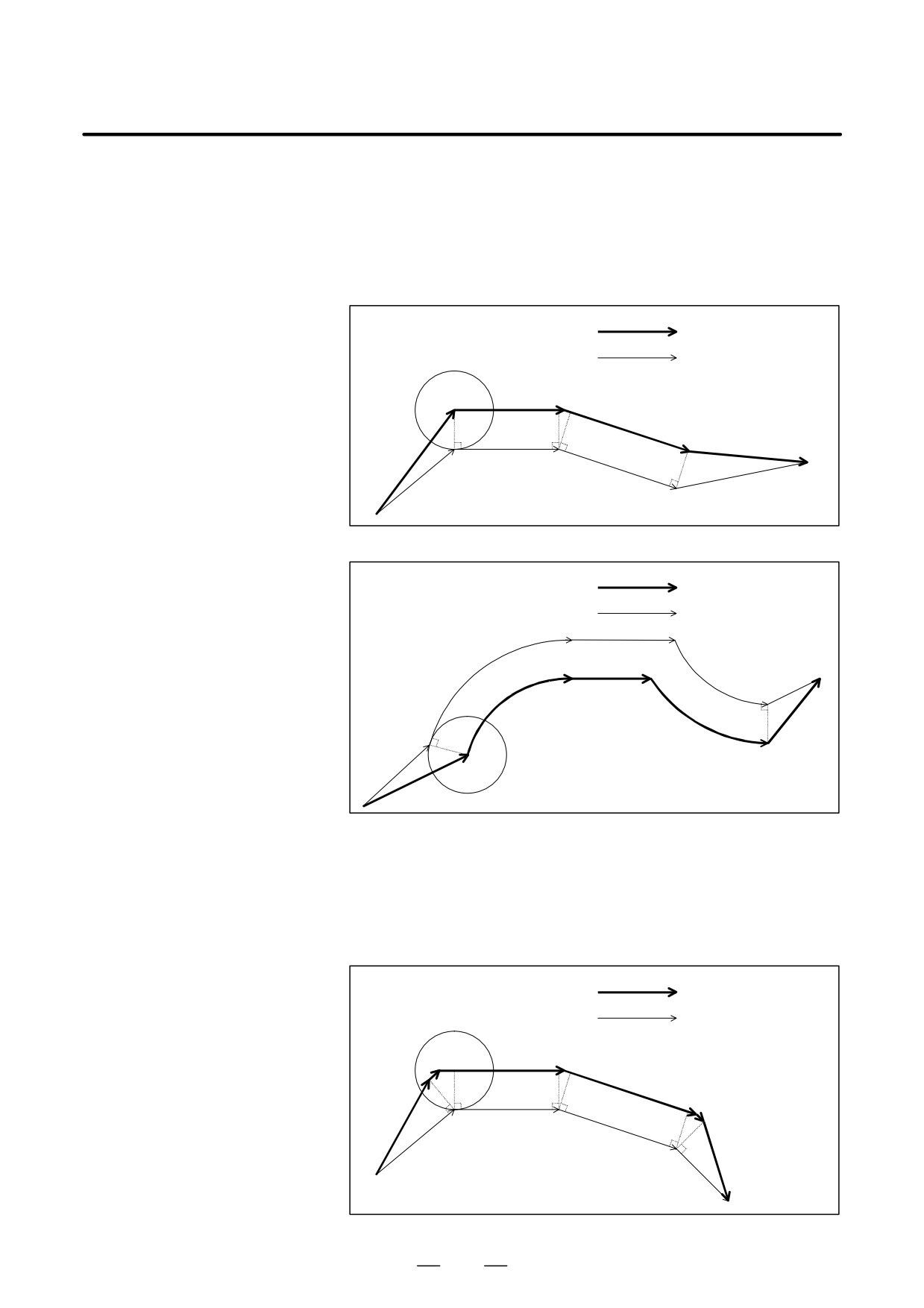
Type A operation is similar to cutter compensation as shown below.
Operation in linear interpolation
:Tool center path
:Programmed tool path
Tool
G40
G41.2
Operation in circular interpolation
:Tool center path
:Programmed tool path
G40
G42.2
Tool
Fig. 22.5.1 (b) Operation at compensation start-up and cancellation
(Type A)
(2) Type B
Type B operation is similar to cutter compensation as shown below.
Operation in linear interpolation
:Tool center path
:Programmed tool path
Tool
G40
G41.2
669