FANUC Series 30i/300i/300is-MODEL A. Machining Center System. User's manual - page 182
 

  Index      Manuals     FANUC Series 30i/300i/300is-MODEL A. Machining Center System. User's manual (B-63944EN/03)


Search            copyright infringement  


Content      ..     180      181      182      183     ..


FANUC Series 30i/300i/300is-MODEL A. Machining Center System. User's manual - page 182


11.PROGRAM MANAGEMENT

 OPERATION 

B-63944EN/03


- 1412 - 

11.12 

PROGRAM COPY FUNCTION


A program is copied or moved from folder to folder.


Procedure for copying a program compact


Press function key 

Press chapter selection soft key [FOLDER]. 
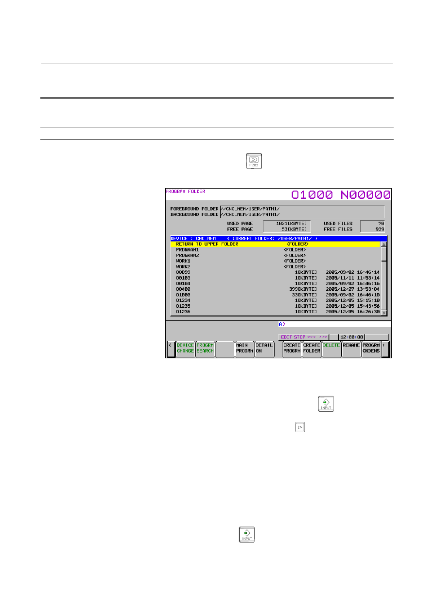
The following program folder screen appears: 


Press the soft key [(OPRT)]. 

4  Display the folder from which the program to be copied or 

moved.  Move the cursor to the folder (indicated by 
<FOLDER>) on the screen and press 

 to move to the 

folder. 

5  Press the continuous menu key 

 until soft key [SELECT 

START] appears. 


Press the soft key [SELECT START]. 

Move the cursor to the program that you want to select, and press 
soft key [SELECT].  The background color of the selected 
program changes to blue to indicate that the program is selected.   
To select multiple programs, repeat this procedure. 

Press the soft key [SELECT END].  The selected program is 
determined. 

8  Display the folder to which the program is to be copied or moved. 

Move the cursor to the folder (indicated by <FOLDER>) on the 
screen and press 

  to move to the folder. 

B-63944EN/03

 OPERATION 

11.PROGRAM MANAGEMENT


- 1413 - 

9  Press soft key [COPY] in the folder to which the selected 

program is copied to copy the program.    If just one program is 
selected, pressing soft key [COPY] after typing a program name 
performs a copy operation with the entered name. 

10  To move the program, press soft key [MOVE].  The selected 

file is then moved.    If just one program is selected, pressing soft 
key [MOVE] after typing a program name performs a move 
operation with the entered name. 


Explanation 

Operations are accepted only when the data protection key is set to 
ON. 
 
If the program storage capacity on the copy destination side is 
insufficient, the copy operation is not accepted. 
 
A selected program can be deselected by pressing [SELECT] again or 
by pressing [CANCEL]. 
 
If a program with the same name is present in the copy or move 
destination, soft keys [NO] and [REWRITE] are displayed together 
with the "REWRITE: FILE NAME" message to ask whether to 
overwrite the existing program.  Pressing [REWRITE] performs 
overwriting, and pressing [NO] does not perform the copy or move 
operation of that program. 
 
Pressing soft key [DELETE] deletes all the files currently selected. 
 
A program can be neither copied nor moved to the same folder as the 
selected folder. 
However, when only one program is selected, if the name of the 
program is entered, the program is copied or moved with the specified 
name to the same folder. 
 

NOTE 

Once a copy or move operation starts, it cannot be 
canceled.    So, start the operation very carefully. 


12.SETTING AND DISPLAYING DATA

 OPERATION 

B-63944EN/03


- 1414 - 

12 

SETTING AND DISPLAYING DATA 

 
To operate a CNC machine tool, various data must be set on the MDI 
panel for the CNC. The operator can monitor the state of operation 
with data displayed during operation. 
This chapter describes how to display and set data for each function. 


Chapter 12, "SETTING AND DISPLAYING DATA", consists of the 
following sections: 

 
12.1  SCREENS DISPLAYED BY FUNCTION KEY 

......1429 

12.2  SCREENS DISPLAYED BY FUNCTION KEY 

......1465 

12.3  SCREENS DISPLAYED BY FUNCTION KEY 

......1571 

12.4  SCREENS DISPLAYED BY FUNCTION KEY 

......1721 

12.5  SCREENS DISPLAYED BY FUNCTION KEY 

......1881 

12.6  DISPLAYING THE PROGRAM NUMBER/NAME, 

SEQUENCE NUMBER, AND STATUS, AND WARNING 
MESSAGES FOR DATA SETTING OR INPUT/OUTPUT 
OPERATION........................................................................1882 

12.7  SCREEN ERASURE FUNCTION AND AUTOMATIC 

SCREEN ERASURE FUNCTION.......................................1892 

12.8  LOAD METER SCREEN ....................................................1894 
 

Explanation 
  - Screen transition chart 

The screen transition for when each function key on the MDI panel is 
pressed is shown below. The subsections referenced for each screen 
are also shown. See the appropriate subsection for details of each 
screen and the setting procedure on the screen. See other chapters for 
screens not described in this chapter. 
See Chapter 7 for the screen that appears when function key 

 is 

pressed.  In general, function key 


 or 


  is prepared by the 

machine tool builder and used for macros. Refer to the manual issued 
by the machine tool builder for the screen that appears when function 
key 


 or 


 is pressed. 


  - Data protection key 

The machine may have a data protection key to protect part programs, 
tool compensation values, setting data, and custom macro variables. 
Refer to the manual issued by the machine tool builder for where the 
data protection key is located and how to use it. 

B-63944EN/03

 OPERATION 

12.SETTING AND DISPLAYING DATA


- 1415 - 

Screen displayed when the function key 

  is pressed (for 7.2/8.4/10.4-inch 

display unit) 


ABS 

REL 

ALL 

HNDL 

(OPRT)

Page 1 

+

(1) (2) (3) (4) (5) 


Ø


Ø


Ø


Ø


Position 
display in
the 
workpiece 
coordinate 
system 

 See III-12.1.1

Position 
display in
the 
workpiece 
coordinate 
system 

 See III-12.1.1

Position 
display in
the 
workpiece 
coordinate 
system 

 See III-12.1.1

Manual 
handle 
interruption 

 See III-4.4


Actual 
feedrate 
display 

 See III-12.1.5

Actual 
feedrate 
display 

 See III-12.1.5

Actual 
feedrate 
display 

 See III-12.1.5


Display of
run time 
and parts
count 

 See III-12.1.6

Display of
run time 
and parts
count 

 See III-12.1.6

Display of
run time 
and parts
count 

 See III-12.1.6


MONI 

3-D 
MANUAL


(OPRT)

Page 2 

+

(6) (7) (8) (9) (10) 


Ø


Ø


Operating 
monitor 
display 

 See III-12.1.8

Display of 
three-dime
nsional 
manual 
feed 

 See III-12.1.9


12.SETTING AND DISPLAYING DATA

 OPERATION 

B-63944EN/03


- 1416 - 

Screen displayed when the function key 

  is pressed (for 15-inch display unit) 


Page 


(1) ALL 

Overall position 
display 

 See III-12.1.10

 Actual 

feedrate 

display 

 See 

III-12.1.12 


Display of run 
time and parts 
count 

 See III-12.1.13


(2) HANDLE 

Manual handle 
interruption 

 See III-4.5 


(3) 

MONITO 

Operating 
monitor display 

 See III-12.1.15


(4) 

3-D 
MANUAL 

Display of 
3-dimensional 
manual feed 

 See III-12.1.16


(5) 

VIRTUAL 
AXIS 


(6) 

ABSOLU 
TE 


(7) 

RELATI 
VE 


B-63944EN/03

 OPERATION 

12.SETTING AND DISPLAYING DATA


- 1417 - 

Screen displayed when the function key 

  is pressed (for 7.2/8.4/10.4-inch 

display unit) 


PROGRA
M


FOLDER

NEXT


CHECK


(OPRT)


Page 1 

+

(1) (2) (3) (4) (5) 


Ø


Ø


Ø


Editing 
programs

 See III-10


Current 
block 
display 
screen 

 See III-12.2.5

Program 
check 
screen 

 See III-12.2.6


Next block 
display 
screen 

 See III-12.2.5


RSTR


JOG 


(OPRT) 

Page 2 

+

(6) (7) (8) (9) (10) 


12.SETTING AND DISPLAYING DATA

 OPERATION 

B-63944EN/03


- 1418 - 

Screen displayed when the function key 

  is pressed (for 15-inch display unit) 


Page 


(1) PROGRM

Editing Programs 

 See III-10 


(2) FOLDER 

Program folder 
screen 

 See III-12.2.13 


(3) CHECK 

Program check 
screen 

 See III-12.2.15 


(4) NEXT 

Current block 
display screen 

 See III-12.2.14 

Next block display 
screen 

 See III-12.2.14 


(5) TIME 

Stamping the 
machining time 

 See III-12.2.17 


(6) JOG 


(7) 

RESTAR 


B-63944EN/03

 OPERATION 

12.SETTING AND DISPLAYING DATA


- 1419 - 

Screen displayed when the function key 

  is pressed (for 7.2/8.4/10.4-inch 

display unit) 


OFFSET

SETTIN 


WORK 


(OPRT)


Page 1 

+

(1) (2) (3) (4) (5) 


Ø


Ø


Ø


Setting 
and 
displaying 
the tool 
offset 
value 

 See III-2.1.1

*1

Displaying 
and 
entering 
setting 
data 

 See III-12.3.1

Displaying 
and setting
the 
workpiece 
origin 
offset 
value 

 See III-12.3.4


MACRO

PATTER 
N MENU 

OPR


TOOL M 
ANAGER 

(OPRT) 

Page 2 

+

(6) (7) (8) (9) (10) 


Ø


Ø


Ø


Displaying 
and setting 
custom 
macro 
common 
variables

 See III-12.3.6

Displaying 
and setting 
pattern 
data inputs

 See III-12.3.15

Displaying 
and setting 
the 
software 
operator's 
panel 

 See III-12.3.8

Setting and 
displaying 
tool 
management 
data 

 See III-12.3.9


OFST.2

W.SHFT

GEOM.2


(OPRT) 

Page 3 

+

(11) (12)  (13)  (14) (15) 


Ø


Ø


Ø


Y-axis 
offset 

 See III-2.1.6

*1

Setting the 
workpiece 
coordinate 
system 
shift value

 See III-2.1.4

*1

Setting tool 
compensation
/ second 
geometry 
offset values

 See III-2.1.5

*1


PR-LV 

EXTEND
OFFSET


(OPRT)


Page 4 

+

(16) (17)  (18)  (19)  (20) 


Ø


Ø


Precision 
level 
selection 

 See III-12.3.12

Setting the 
4th/5th 
axis offset

 See III-2.1.8

*1


Content      ..     180      181      182      183     ..