FANUC Series 30i/300i/300is-MODEL A. Machining Center System. User's manual - page 139
 

  Index      Manuals     FANUC Series 30i/300i/300is-MODEL A. Machining Center System. User's manual (B-63944EN/03)


Search            copyright infringement  


Content      ..     137      138      139      140     ..


FANUC Series 30i/300i/300is-MODEL A. Machining Center System. User's manual - page 139


3.MANUAL OPERATION

 OPERATION 

B-63944EN/03


- 1068 - 

 
(Example)  When the tool rotation axes are B-axis and C-axis and the tool axis 

direction is the Z-axis direction 

C


B

Z

Y


X

Tool axis right-angle direction 2


Tool axis direction


B

C

Tool axis right-angle direction 1


Y

X


Z


B

C


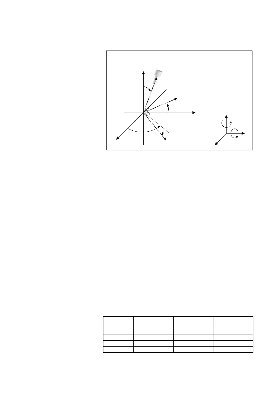
  - Latitude and longitude directions 

When bit 1 (FLL) of parameter No. 12320 is set to 1, the feed direction 
is defined as follows: 
Let a vector perpendicular to a plane formed by the tool axis direction 
vector (

T

r

) and normal axis direction vector (

P

r

) (parameter No. 

12321) be the tool axis right-angle direction 1 (longitude direction) 
vector (

1

r

R

).  When tool axis right-angle direction 1 is selected, a 

movement in the positive direction means a movement in this vector 
direction, and a movement in the negative direction means a movement 
in the direction opposite to the vector direction.    (Longitude direction 
feed) 
Equation:  

T

P

R

r

r

r

×

=

1


Let a vector perpendicular to the tool axis direction vector (

T

r

) and 

tool axis right-angle direction 1 (longitude direction) vector (

1

r

R

) be 

the tool axis right-angle direction 2 (latitude direction) vector (

2

R

r

).  

When tool axis right-angle direction 2 is selected, a movement in the 
positive direction means a movement in this vector direction, and a 
movement in the negative direction means a movement in the direction 
opposite to the vector direction.    (Latitude direction) 
Equation:  

1

2

R

T

R

r

r

r

×

=


When the tool axis direction vector (

T

r

) is parallel to the normal axis 

direction vector (

P

r

) (parameter No. 12321) (when the angle between 

them is not greater than the setting of parameter No. 12322), tool axis 
right-angle direction 1 and tool axis right-angle direction 2 are 
assumed as follows: 


Parameter 

No.12321 

Normal axis 

direction 

Tool axis 

right-angle 

direction 1 

Tool axis 

right-angle 

direction 2 

1   

+X direction 

+Y direction 

+Z direction 

2   

+Y direction 

+Z direction 

+X direction 

+Z direction 

+X direction 

+Y direction 

B-63944EN/03

 OPERATION 

3.MANUAL OPERATION


- 1069 - 

If 0 is set in parameter No. 12321, the normal axis direction is set to 
the reference tool axis direction (parameter No. 19697). 
If a value other than 0 to 3 is specified in parameter No. 12321, alarm 
PS5459 is issued. 


  - Tool axis right-angle direction feed in the tilted working plane command mode 

If bit 0 (TWD) of parameter No. 12320 is set to 1, the feed direction of 
the tool axis right-angle direction feed in the tilted working plane 
command mode is defined as follows: 

Tool axis right-angle direction 1:  X direction in the feature 
coordinate system of the tilted working plane command 
Tool axis right-angle direction 2:  Y direction in the feature 
coordinate system of the tilted working plane command 


  - Tool axis right-angle direction handle feed 

The tool axis right-angle direction handle feed is enabled when the 
following four conditions are satisfied: 
<1>  Handle mode is selected. 
<2>  The tool axis right-angle direction feed mode signal (RGHTH) is 

set to "1" and the table base signal (TB_BASE) is set to "0". 

<3> The state of the first manual handle feed axis selection signals 

(HS1A - HS1E) to make the tool axis right-angle direction 
handle feed mode effective is set in parameter No.12311 or 
No.12312. 

<4>  The value of parameter No.12311 or No.12312 matches the first 

manual handle feed axis selection signals (HS1A - HS1E). 


    Amount of movement 

When the manual pulse generator is rotated, the tool is moved in the 
tool axis right-angle direction by the amount of rotation. 
 

Tool axis 
right-angle direction 1 
(longitude direction): R1

Tool axis 
right-angle direction 2
(latitude direction): R2

Normal axis direction: P 

Tool axis direction: T

3.MANUAL OPERATION

 OPERATION 

B-63944EN/03


- 1070 - 

    Feedrate clamp 

The feedrate is clamped so that the speed of each moving axis dose 
not exceed the manual rapid traverse rate (parameter No.1424).  
Handle pulses generated while the clamp feedrate is exceeded are 
ignored. 
 

  - Tool axis right-angle direction JOG feed/tool axis right-angle direction 

incremental feed 

The tool axis right-angle direction JOG feed or tool axis right-angle 
direction incremental feed is enabled when the following three 
conditions are satisfied: 
<1>  JOG mode or incremental feed mode is selected. 
<2>  The tool axis right-angle direction feed mode signal (RGHTH) is 

set to "1" and the table base signal (TB_BASE) is set to "0". 

<3>  The feed axis direction selection signal (+Jn, -Jn (where n = 1 to 

the number of controlled axes)) is set to "1" for the axis 
corresponding to the direction that is perpendicular to the 
direction specified by parameter No.19697.  (Even when the 
tool axis direction is slant because of the settings of parameters 
No.19698 and No.19699, the signal that activates the tool axis 
right-angle direction JOG feed or tool axis right-angle direction 
incremental feed is determined by parameter No.19697 only.) 
Ex.) No.19697=3 (+Z-axis direction); X-, Y-, and Z-axes are the 

1st, 2nd, and 3rd axes respectively. 


+J1  : Tool axis right-angle direction 1 + 


-J1  : Tool axis right-angle direction 1 - 


+J2  : Tool axis right-angle direction 2 + 


-J2  : Tool axis right-angle direction 2 - 


    Feedrate 

The feedrate is the dry run rate (parameter No.1410).  The manual 
feedrate override feature is available. 
If bit 2 (JFR) of parameter No. 12320 is set to 1, the feedrate is the jog 
feedrate (parameter No. 1423) for a driven feed axis direction 
selection signal.    The manual feedrate override feature is available. 
 

    Feedrate clamp 

The feedrate is clamped so that the speed of each moving axis dose 
not exceed the manual rapid traverse rate (parameter No.1424). 
 

B-63944EN/03

 OPERATION 

3.MANUAL OPERATION


- 1071 - 

3.9.3 

Tool Tip Center Rotation Handle Feed / Tool Tip Center 

Rotation JOG Feed / Tool Tip Center Rotation Incremental 

Feed 


Overview 

In the tool tip center rotation handle feed, tool tip center rotation JOG 
feed, and tool tip center rotation incremental feed, when a rotary axis 
is rotated by manual feed, the linear axes (X, Y, and Z axes) are 
moved so that turning the rotation axis does not change the relative 
relationship between the tool tip position and the workpiece (table). 
 

  The following figure shows an example where the tool is rotated on 

the rotation axis.    In this case, the linear axes are moved so that the 
position of the tool tip is not moved with respect to the workpiece. 


Workpiece

Tool tip position 


 The following figure shows an example where the table is rotated 

on the rotation axis.  As in the previous case, the linear axes are 
moved so that the position of the tool tip is not moved with respect 
to the workpiece (table). 


B


Z

Y


X


B


B


Table

Workpiece


3.MANUAL OPERATION

 OPERATION 

B-63944EN/03


- 1072 - 

  - Tool tip center rotation handle feed 

The tool tip center rotation handle feed is enabled when the following 
four conditions are satisfied: 
<1>  Handle mode is selected. 
<2> The tool tip center rotation feed mode signal (RNDH) is set to 

"1". 

<3> The state of the first manual handle feed axis selection signals 

(HS1A - HS1E) to make the tool tip center rotation handle feed 
mode effective is set in parameter No.12313 or No.12314. 

<4>  The value of parameter No.12313 or No.12314 matches the first 

manual handle feed axis selection signals (HS1A - HS1E). 


    Amount of movement 

When the manual pulse generator is rotated, the rotation axis is moved 
by the amount of rotation.  The linear axes (X, Y, and Z axes) are 
moved so that turning the rotation axis does not change the relative 
relationship between the tool tip position and the workpiece. 
 

    Feedrate clamp 

The feedrate is clamped so that the synthetic speed of the linear axes 
(in the tangential direction) does not exceed the manual rapid traverse 
rate (parameter No.1424) (of any moving linear axis).    The feedrate 
is also clamped so that the speed of the rotation axis does not exceed 
the manual rapid traverse rate (parameter No.1424) (of that particular 
axis).    Handle pulses generated while the clamp feedrate is exceeded 
are ignored. 
 

  - Tool tip center rotation JOG feed/tool tip center rotation incremental feed 

The tool tip center rotation JOG feed or tool tip center rotation 
incremental feed is enabled when the following three conditions are 
satisfied: 
<1>  JOG mode or incremental feed mode is selected. 
<2> The tool tip center rotation feed mode signal (RNDH) is set to 

"1". 

<3>  The feed axis direction selection signal (+Jn, -Jn (where n = 1 to 

the number of controlled axes)) is set to "1" for the rotation axis 
to be rotated. 
Ex.)  When the B-axis (4th axis) is rotated 


+J4  : Tool tip center rotation feed + 


-J4  : Tool tip center rotation feed - 


    Feedrate 

Control is exerted so that the synthetic speed of the linear axes (in the 
tangential direction) is the dry run rate (parameter No.1410).  The 
manual feedrate override feature is available. 
If bit 2 (JFR) of parameter No. 12320 is set to 1, the feedrate of a 
rotation axis is the jog feedrate of the axis to be rotated (parameter No. 
1423).    The manual feedrate override feature is available. 
 

B-63944EN/03

 OPERATION 

3.MANUAL OPERATION


- 1073 - 

    Feedrate clamp 

The feedrate is clamped so that the synthetic speed of the linear axes 
(in the tangential direction) does not exceed the manual rapid traverse 
rate (parameter No.1424) (of any moving linear axis).    The feedrate 
is also clamped so that the speed of the rotation axis does not exceed 
the manual rapid traverse rate (parameter No.1424) (of that particular 
axis). 
 

  - Selection of the tool length offset value 

The tool length in three-dimensional manual feed is determined as 
explained below.    Table 3.9.3 (a)) 
If bit 2 (LOD) of parameter No. 19746 is set to 0, the value set in 
parameter No. 12318 is assumed to be the tool length. 
If the LOD parameter is set to 1, and the tool length offset function is 
performed, the offset data specified for the tool length offset is 
assumed to be the tool length. 
If the LOD parameter is set to 1, and the tool length offset function is 
not performed, the tool length is determined as follows.  If bit 3 
(LOZ) of parameter No. 19746 is set to 0, the value set in parameter 
No. 12318 is assumed to be the tool length in three-dimensional 
manual feed; if LOZ is set to 1, the tool length is assumed to be 0. 
 

Table 3.9.3 (a)    Tool length offset value in three-dimensional manual 

feed 

Parameter No. 19746#2(LOD) 

= 1 


= 0 

Tool length 

offset enabled 

Tool length offset 

canceled 


= 0

Parameter No. 12318


Parameter 

No. 19746#3

(LOZ) 

= 1


Parameter

No. 12318


Offset data 

 
The tool length offset function is enabled when the following two 
conditions are both satisfied: 


The tool length offset function listed below is enabled (modal 
code of group 8 except G49) 
- G43

G44     : Tool length compensation 

- G43.4

G43.5    : Tool center point control 


The H/D code is other than 0. 

 
If bit 6 (CLR) of parameter No. 3402 is set to 0 not to clear the tool 
length offset vector, G codes of group 8, and H codes at the time of a 
reset, the tool length offset status is maintained when a reset is made 
in the tool length offset mode. 


3.MANUAL OPERATION

 OPERATION 

B-63944EN/03


- 1074 - 

3.9.4 

Table Vertical Direction Handle Feed / Table Vertical Direction 

JOG Feed / Table Vertical Direction Incremental Feed 


Overview 

In the table vertical direction handle feed, table vertical direction JOG 
feed, and table vertical direction incremental feed, the tool is moved in 
the table vertical direction. 
 

Explanation 


  - Table vertical direction 

The table vertical direction is a direction vertical to the table.    It is 
equal to the tool axis direction specified in parameter No.19697 when 
all of the rotation axes for controlling the table are at a an angle of 0 
degree.  When the rotation axes for controlling the table rotate, the 
table vertical direction changes according to the rotation axis angle. 
 

B

B

Z

Y

X

Table vertical direction


  - Table-based vertical direction feed in the tilted working plane command mode 

If bit 0 (TWD) of parameter No. 12320 is set to 1, the feed direction of 
the table-based vertical direction feed in the tilted working plane 
command mode is assumed to be the Z direction in the feature 
coordinate system of the tilted working plane command. 


  - Table vertical direction handle feed 

The table vertical direction handle feed is enabled when the following 
four conditions are satisfied: 
<1>  Handle mode is selected. 
<2> Both the tool axis direction feed mode signal (ALNGH) and the 

table base signal (TB_BASE) are set to "1". 

<3> The state of the first manual handle feed axis selection signals 

(HS1A - HS1E) to make the table vertical handle feed mode 
effective is set in parameter No.12310. 

<4> The value of parameter No.12310 matches the first manual 

handle feed axis selection signals (HS1A - HS1E). 


B-63944EN/03

 OPERATION 

3.MANUAL OPERATION


- 1075 - 

    Amount of movement 

When the manual pulse generator is rotated, the tool is moved in the 
table vertical direction by the amount of rotation. 
 

    Feedrate clamp 

The feedrate is clamped so that the speed of each moving axis dose 
not exceed the manual rapid traverse rate (parameter No.1424).  
Handle pulses generated while the clamp feedrate is exceeded are 
ignored. 
 

  - Table vertical direction JOG feed/table vertical direction incremental feed 

The table vertical direction JOG feed or table vertical direction 
incremental feed is enabled when the following three conditions are 
satisfied: 
<1>  JOG mode or incremental feed mode is selected. 
<2> Both the tool axis direction feed mode signal (ALNGH) and the 

table base signal (TB_BASE) are set to "1". 

<3>  The feed axis direction selection signal [+Jn,-Jn (where n = 1 to 

the number of controlled axes)] is set to "1" for the axis 
corresponding to the direction specified by parameter No.19697. 
Ex.)  No.19697 = 3 (+Z-axis direction); Z-axis is the 3rd axis. 


+J3  : Table vertical direction + 


-J3  : Table vertical direction - 


    Feedrate 

The feedrate is the dry run rate (parameter No.1410).  The manual 
feedrate override feature is available. 
If bit 2 (JFR) of parameter No. 12320 is set to 1, the feedrate is the jog 
feedrate (parameter No. 1423) for a driven feed axis direction 
selection signal.    The manual feedrate override feature is available. 
 

    Feedrate clamp 

The feedrate is clamped so that the speed of each moving axis dose 
not exceed the manual rapid traverse rate (parameter No.1424). 


Content      ..     137      138      139      140     ..