FANUC Series 30i/300i/300is-MODEL A. Machining Center System. User's manual - page 101
 

  Index      Manuals     FANUC Series 30i/300i/300is-MODEL A. Machining Center System. User's manual (B-63944EN/03)


Search            copyright infringement  


Content      ..     99      100      101      102     ..


FANUC Series 30i/300i/300is-MODEL A. Machining Center System. User's manual - page 101


21.AXIS CONTROL FUNCTIONS

 PROGRAMMING 

B-63944EN/03


- 764 - 

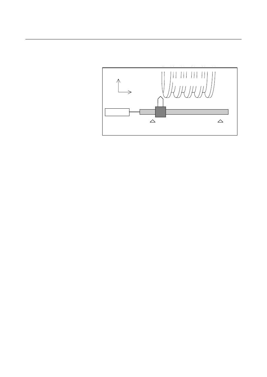
  - Example of use of dressing 

Gear grinder in the following machine configuration 


Limit switch 1

Limit switch 2

V-axis motor

U-axis

V-axis

Rotary whetstone 


O9500 ;   
N01  G01  G91  U

_

    F100 ; 

Dressing axis approach 

N02  M03  S100 ; 

The M03 command causes the PMC to rotate the 
whetstone in the positive direction. 
In accordance with this, the tool moves along the V-axis 
in the + direction.    When the tool reaches the position of 
limit switch 2 on the V-axis, the PMC stops the 
whetstone and returns FIN. 

N02  U

_

    V

_

  ; 

Movement to the next dressing position 

N03  M04  S100 ; 

The M04 command causes the PMC to rotate the 
whetstone in the negative direction. 
In accordance with this, the tool moves along the V-axis 
in the - direction.    When the tool reaches the position of 
limit switch 1 on the V-axis, the PMC stops the 
whetstone and returns FIN. 

N04  U

_

  V

_

  ; 

Movement to the next dressing position 
If required, N02 to N04 are repeated to conduct dressing. 

..........  
..........  


M99 ;   


B-63944EN/03

 PROGRAMMING 

21.AXIS CONTROL FUNCTIONS


- 765 - 

NOTE 


If the V-axis (linear axis) is synchronized with the 
spindle as in dressing, the V-axis travel range is 
determined by the rotation of the spindle.    To 
perform dressing with the tool moving back and 
forth along the V-axis in a certain range, therefore, 
the PMC must perform an operation in which the 
tool is stopped temporarily and is reversed when it 
reaches a certain position on the V-axis. 
In the above example, limit switches are provided to 
determine the range of travel along the V-axis and 
the PMC performs control so that the whetstone 
rotates until the tool reaches the position of each 
limit switch on the V-axis. 
By using the position switch function instead of limit 
switches, dressing can be performed as in the 
following example, without the need to mount limit 
switches to the machine.    By rewriting the 
operating ranges of the position switches 
(parameters Nos. 6930 to 6945 and Nos. 6950 to 
6965) using the G10 programming Parameter input, 
the range of travel along the V-axis can be specified 
using a program. 


  - Command specification for hobbing machines 

Based on the controlled axis configuration described in Fig. 21.7.4.3 
(a), the sample program below sets the C-axis (in parameter 7710) for 
starting synchronization with the spindle according to the command 
specification method for hobbing machines. 
 

O1234 ;   
N0010  M19  ; 

Performs tool axis orientation. 

N0020  G28  G91  C0  ;  Performs reference position return along the workpiece axis. 
N0030  G81  T20  L1 ;  Starts synchronization with the spindle and C-axis at the ratio of 

a 18

°

 rotation about the C-axis to one spindle rotation. 

 
N0040    S300    M03 ; 

Rotates the spindle at 300 min

-1

N0050    G01    X...    F... ; 

Makes a movement along the X-axis (for cutting). 

N0060    G01    Y...    F... ; 

Makes a movement along the Y-axis (for grinding).   


Axes such as the C-axis, X-axis, and Y-axis can be specified as 
required. 

N0100    G01    X...    F... ; 

Makes a movement along the X-axis (for retraction). 

N0110    M05 ; 

Stops the spindle. 

N0120    G80 ; 

Cancels the synchronization between the spindle and C-axis. 

N0130  M30 ; 


21.AXIS CONTROL FUNCTIONS

 PROGRAMMING 

B-63944EN/03


- 766 - 

21.7.4.5 

Synchronization ratio specification range 

 
The programmed ratio (synchronization ratio) of a movement along 
the slave axis to a movement along the master axis is converted to a 
detection unit ratio inside the NC. If such converted data (detection 
unit ratio) exceeds a certain allowable data range in the NC, 
synchronization cannot be established correctly, and an alarm PS1596 
is issued. 
Even when a programmed master axis movement and a programmed 
slave axis movement are within specifiable ranges, a detection unit 
ratio obtained by conversion can exceed the allowable range, thus 
resulting in an alarm. 
Let K be a synchronization ratio. The internal data corresponding K is 
the amount of slave axis movement (Kn) represented in the detection 
unit divided by the amount of master axis movement (Kd) represented 
in the detection unit;   
this fraction is represented as Kn/Kd (reduced to its lowest terms) as 
indicated below. 
 

unit

detection 


in the


d

represente

movement 


axis

master 


of

Amount 

unit

detection 


in the


d

represente

movement 


axis


slave


of

Amount 

Kd

Kn

K

=

=


Kn and Kd must lie within the following ranges: 
 
-2147483648  

 Kn 

 2147483647 

 1 

 Kd 

 65535   

 
When Kn or Kd exceeds its allowable range above, an alarm PS1596 
is issued. 
In conversion to the detection unit, when the CMR (command 
multiplication: parameter 1820) is a fraction or when inch/millimeter 
conversion is used, the fraction is directly converted without 
modification so that no error can occur in the conversion of specified 
amounts of movement. 
During conversion, the amount of movement is multiplied by 254/100 
for inch input on a millimeter machine, and 100/254 for metric input 
on an inch machine. Thus, Kn and Kd can become large numbers. If a 
synchronization ratio cannot be reduced to its lowest terms, an alarm 
condition is likely to occur. 
 

 - Example 1) 

Based on the controlled axis configuration described in Fig. 21.7.4.3 
(a), suppose that the spindle and V-axis are as follows: 
Spindle pulse coder 

: 72000pulse/rev (4 pulses for one 

A/B phase cycle) 

C-axis least command increment  :  0.001deg 
C-axis CMR 

:  5 

V-axis least command increment  :  0.001mm 
V-axis CMR 

:  5 


B-63944EN/03

 PROGRAMMING 

21.AXIS CONTROL FUNCTIONS


- 767 - 

Then, the C-axis detection unit is 0.0002 degree. The V-axis detection 
unit is 0.0002 mm. In this case, the synchronization ratio (Kn, Kd) is 
related with a command as indicated below. Here, let Pm and Ps be 
the amounts of movements represented in the detection unit on the 
master axis and slave axis specified in a synchronization start 
command, respectively. 
 
(1)  When the master axis is the spindle, and the slave axis is the 

C-axis 
(a)  Command : G81.5  T10  C0  L1  ; 
 

Operation : Synchronization between the spindle and C-axis 

is started at the ratio of one rotation about the 
C-axis to ten spindle rotations. 


Pm 

: (Number of pulses per spindle rotation) 

×

 (10 

rotations) 

 72000 

×

 10 


Ps 

: (Amount of movement per rotation about the 

C-axis) 

×

 CMR 

×

 (one rotation) 

 360000 

×

 5 

×

 1 


Kn
Kd = 

360000

×

5

×

1

72000

×

10

 = 

5


Both Kn and Kd are within the allowable range. No alarm is 
output. 

 
(b)  Command : G81.5  T10  C0  L-1  ; 
 

Operation : Synchronization between the spindle and C-axis 

is started at the ratio of one rotation about the 
C-axis to ten spindle rotations. 


  In this case, however, the direction of rotation 

is opposite to that of (a) above. 


Pm 

: (Number of pulses per spindle rotation) 

×

 (10 

rotations) 

 72000 

×

 10   


Ps 

: (Amount of movement per rotation about the 

C-axis) 

×

 CMR 

×

 (one rotation) 

 -360000 

×

 5 

×

 1 


Kn
Kd = 

-360000

×

5

×

1

72000

×

10

 = 

-5

2  


Both Kn and Kd are within the allowable range. No alarm is 
output. 

 
(c)  Command : G81.5  T1  C3.263  ; 
 

Operation : Synchronization between the spindle and C-axis 

is started at the ratio of a 3.263-degree rotation 
about the C-axis to one spindle rotation. 


Pm 

: (Number of pulses per spindle rotation) 

×

 (one 

rotation) 

 72000 

×

 1 


Ps 

: (Amount of C-axis movement) 

×

 CMR 

 3263 

×

 5   


21.AXIS CONTROL FUNCTIONS

 PROGRAMMING 

B-63944EN/03


- 768 - 


Kn
Kd = 

3263

×

5

72000

×

1

 = 

3263

14400 


Both Kn and Kd are within the allowable range. No alarm is 
output. 


In this sample program, when T1 is specified for the master 
axis, the synchronization ratio (fraction) of the CMR of the 
C-axis to the denominator Kd can always be reduced to 
lowest terms, thus Kd falls in the allowable range. So, the 
specifiable range of C is as follows: 
 -99999999 

 C 

 99999999 

 
(d)  Command : G81.5  T10  C3.263  ; 
 

Operation : Synchronization between the spindle and C-axis 

is started at the ratio of a 3.263-degree rotation 
about the C-axis to ten spindle rotations. 


Pm 

: (Number of pulses per spindle rotation) 

×

 (10 

rotations) 

 72000 

×

 10   


Ps 

: (Amount of C-axis movement) 

×

 CMR 

 3263 

×

 5 


Kn
Kd = 

3263

×

5

72000

×

10

 = 

3263

144000 


In this case, an alarm is issued because Kd exceeds the 
specifiable range. 

 
(e)  Command : G81.5  P10000  C-0.214  ; 
 

Operation : Synchronization between the spindle and C-axis 

is started at the ratio of a -0.214 degree rotation 
of the C-axis to 10,000 feedback pulses from 
the pulse coder of the spindle. 


Pm 

: (Specified number of feedback pulses from the 

pulse coder of the spindle) 

 10000   


Ps 

: (Amount of C-axis movement) 

×

 CMR 

 -214 

×

 5 


Kn
Kd = 

-214

×

5

10000  = 

-107

1000 


Both Kn and Kd are within the allowable range. No alarm is 
output. 


(2)  When the master axis is the spindle, the slave axis is the V-axis 

(linear axis), and inch/metric conversion is performed 
(a)  For a millimeter machine and metric input 
 

Command : G81.5  T1  V1.0  ; 

  Operation 

Synchronization between the spindle and 
V-axis is started at the ratio of a 1.0 inch 
movement (25.4 mm) along the V-axis per 
spindle rotation. 


Pm 

: (Number of pulses per spindle rotation) 

×

 (one 

rotation) 

 72000 

×

 1 

B-63944EN/03

 PROGRAMMING 

21.AXIS CONTROL FUNCTIONS


- 769 - 


Ps 

: (Amount of V-axis movement) 

×

 CMR 

 1000 

×

 5 


Kn
Kd = 

1000

×

5

72000  = 

5

72 


Both Kn and Kd are within the allowable range. No alarm is 
output. 

 
(b)  For a millimeter machine and inch input 
 

Command : G81.5  T1  V1.0  ; 

  Operation 

Synchronization between the spindle and 
V-axis is started at the ratio of a 1.0inch 
(25.4mm) movement along the V-axis per 
spindle rotation. 


Pm 

: (Number of pulses per spindle rotation) 

×

 (one 

rotation) 

 72000 

×

 1 


Ps 

: (Amount of V-axis movement) 

×

 CMR 

×

 254 

÷


100 

 10000 

×

 5 

×

 254 

÷

 100 


Kn
Kd = 

10000

×

5

×

254

72000

×

100

 = 

127

72  


Both Kn and Kd are within the allowable range. No alarm is 
output. 

 
(c)  For a millimeter machine and inch input 
 

Command : G81.5  T1  V0.0013  ; 

  Operation 

Synchronization between the spindle and 
V-axis is started at the ratio of a 0.0013 inch 
(0.03302 mm) movement along the V-axis per 
spindle rotation. 


Pm 

: (Number of pulses per spindle rotation) 

×

 (one 

rotation) 

 72000 

×

 1 


Ps 

: (Amount of V-axis movement) 

×

 CMR 

×

 254 

÷


100 

 13 

×

 5 

×

 254 

÷

 100 


Kn
Kd = 

13

×

5

×

254

72000

×

100

 = 

1651

720000 


In this case, an alarm is issued because Kd exceeds the 
specifiable range. 


 - Example 2) 

Based on the controlled axis configuration described in Fig. 21.7.4.3 
(a), suppose that the spindle and V-axis are as follows: 
Spindle pulse coder 

: 72000pulse/rev (4 pulses for one 

A/B phase cycle) 

C-axis least command increment  :  0.001deg 
C-axis CMR  

:  1/2 

V-axis least command increment  :  0.001mm 
V-axis CMR 

:  1/2 


21.AXIS CONTROL FUNCTIONS

 PROGRAMMING 

B-63944EN/03


- 770 - 

Then, the C-axis detection unit is 0.002 degree.    The V-axis detection 
unit is 0.002 mm.   
 
In this case, the synchronization ratio (Kn, Kd) is related with a 
command as indicated below.    Here, let Pm and Ps be the amounts of 
movements represented in the detection unit for the master axis and 
slave axis specified in a synchronization start command, respectively. 
(1)  When the master axis is the spindle, and the slave axis is the 

C-axis 
(a)  Command : G81.5  T1  C3.263  ; 
 

Operation : Synchronization between the spindle and C-axis 

is started at the ratio of a 3.263-degree rotation 
about the C-axis per spindle rotation. 


Pm 

: (Number of pulses per spindle rotation) 

×

 (one 

rotation) 

 72000 

×

 1 


Ps 

: (Amount of C-axis movement)  

×

 CMR 


3263 

×

 1 

÷

 2 


Kn
Kd = 

3263

×

1

72000

×

2

 = 

3263

144000 


In this case, an alarm is issued because Kd exceeds the 
specifiable range. 

 
(b)  Command : G81.5  T1  C3.26  ; 

The value specified for C slightly differs from 
that specified for C in (a). 


Operation : Synchronization between the spindle and C-axis 

is started at the ratio of a 3.26-degree rotation 
about the C-axis per spindle rotation. 


Pm 

: (Number of pulses per spindle rotation) 

×

 (one 

rotation) 

 72000 

×

 1 


Ps 

: (Amount of C-axis movement)  

×

 CMR 


3260 

×

 1 

÷

 2 


Kn
Kd = 

3260

×

1

72000

×

2

 = 

163

7200 


(a) causes an alarm to be output because the values cannot 
be reduced.  (b) causes no alarm because the ratio of the 
travel distances can be reduced to a simple ratio. 


21.7.4.6 

Retract function 

 
See "Retract function" in the Subsection 21.7.4, "Electronic Gear 
Box". 
 

B-63944EN/03

 PROGRAMMING 

21.AXIS CONTROL FUNCTIONS


- 771 - 

21.8 

TANDEM CONTROL 

 
When enough torque for driving a large table cannot be produced by 
only one motor, two motors can be used for movement along a single 
axis.Positioning is performed by the main motor only. The submotor 
is used only to produce torque. With this tandem control function, the 
torque produced can be doubled. 

Table

Ball screw

Main motor

Sub motor


Fig. 21.8 (a)    Example of operation 

 
In general, the NC regards tandem control as being performed for one 
axis. However, for servo parameter management and servo alarm 
monitoring, tandem control is regarded as being performed for two 
axes. 
For details, refer to the relevant manual published by the machine tool 
builder. 


Content      ..     99      100      101      102     ..