FANUC Series 30i/300i/300is-MODEL A. Machining Center System. User's manual - page 91
 

  Index      Manuals     FANUC Series 30i/300i/300is-MODEL A. Machining Center System. User's manual (B-63944EN/03)


Search            copyright infringement  


Content      ..     89      90      91      92     ..


FANUC Series 30i/300i/300is-MODEL A. Machining Center System. User's manual - page 91


 PROGRAMMING 

B-63944EN/03


- 684 - 

20. HIGH-SPEED CUTTING 

FUNCTIONS 

P0

P1

P2

0

1000

2000

3000

4000

5000

6000

7000

0

8000

16000

24000

32000

40000

48000

Speed mm/min

Acceleration mm/sec

2

P5


Fig. 20.4 (h)    Acceleration pattern in case of + move and acceleration 

 
(2)  In case of plus move (up) and deceleration 
 

Because torque of Gravity and friction work forward to the 
output torque of motor, the torque for acceleration/deceleration is 
as follows. 
Maximum torque 

:  130(=100+20+10) (Nm)     


  Speed 0 to 2000(min

-1

)  

Torque at rapid traverse  :  109(=79+20+10) (Nm)   
  

Speed 

3000(min

-1

)  

Minimum torque 

:  88(=58+20+10) (Nm)   


Speed 

4000(min

-1

)  


0

50

100

150

0

1000

2000

3000

4000

Speed(min

-1

)

Torque(Nm)

P0

P1

P5


Fig. 20.4 (i)    Torque for Acc/Dec in case of + move and deceleration 

 
Parameter setting is as follows, 

 Parameter 

No. 

Setting

Unit 

Remarks 

Acceleration 
at P0 

19557 

13514 

0.01% 

Set half the acceleration at P1, or 13514.

Acceleration 
at P1-P2 

19558, 19559 

27027 

0.01% 

At P1 and P2, 130(Nm) can be used for 
the acceleration/ deceleration, so set the 
ratio 11146 (mm/sec

2

) to 4124 (mm/sec

2

).

(2.7027 = 11146 / 4124) 

Acceleration 
at P3-P4 

19560 to 19561 

0.01% 

0 is set because P3 to P4 are skipped. 

Acceleration 
at P5 

19562 22662 

0.01% 

At P5, 109(Nm) can be used for the 
acceleration/deceleration, so set the ratio 
9346 (mm/sec2) to 4124 (mm/sec2). 
(2.2662 = 9346 / 4124) 


B-63944EN/03

 PROGRAMMING 


- 685 - 

20.HIGH-SPEED CUTTING

FUNCTIONS

P0

P1

P2

0

2000

4000

6000

8000

10000

12000

0

8000

16000

24000

32000

40000

48000

Speed mm/min

Acceleration mm/sec

2

P5


Fig. 20.4 (j)    Acceleration pattern in case of + move and deceleration 

 
(3)  In case of minus move (down) and acceleration 
 

Because torque of Gravity works forward to the output torque of 
motor and torque of friction works against the output torque of 
motor, torque for acceleration/deceleration is as follows. 
Maximum torque 

:  110(=100+20-10) (Nm)     


  Speed 0 to 2000(min

-1

Torque at rapid traverse  :  89(=79+20-10) (Nm)   
  

Speed 

3000(min

-1

Minimum torque 

:  68(=58+20-10) (Nm)   


Speed 

4000(min

-1


0

50

100

150

0

1000

2000

3000

4000

Speed(min

-1

)

Torque(Nm)

P0

P1

P5


Fig. 20.4 (k)    Torque for Acc/Dec in case of - move and acceleration 

 
Parameter setting is as follows, 

 Parameter 

No. 

Setting

Unit 

Remarks 

Acceleration at 
P0 

19551 11435 

0.01% 

Set half the acceleration at P1, or 
11435. 

Acceleration at 
P1-P2 

19552,19553 22869 

0.01% 

At P1 and P2, 110(Nm) can be used 
for the acceleration/ deceleration, so 
set the ratio 9431 (mm/sec

2

) to 4124 

(mm/sec

2

). 

(2.2869 = 9431 / 4124) 

Acceleration at 
P3-P4 

19554 to 19555 

0.01% 

0 is set because P3 to P4 are 
skipped. 

Acceleration at 
P5 

19556 18504 

0.01% 

At P5, 89(Nm) can be used for the 
acceleration/deceleration, so set the 
ratio 7631 (mm/sec

2

) to 4124 

(mm/sec

2

). 

(1.8504 = 7631 / 4124) 

 PROGRAMMING 

B-63944EN/03


- 686 - 

20. HIGH-SPEED CUTTING 

FUNCTIONS 


P0

P1

P2

0

1000

2000

3000

4000

5000

6000

7000

8000

9000

10000

0

8000

16000

24000

32000

40000

48000

Speed mm/min

Acceleration mm/sec

2

P5


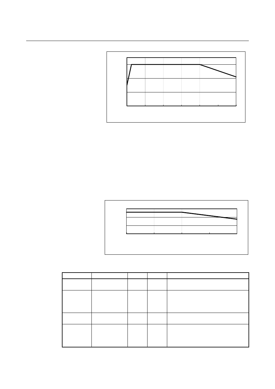
Fig. 20.4 (l)    Acceleration pattern in case of - move and acceleration 


(4)  In case of minus move (down) and deceleration 
 

Because torque of Gravity works against the output torque of 
motor and torque of friction works forward to the output torque 
of motor, torque for acceleration/deceleration is as follows. 
Maximum torque 

:  90(=100-20+10) (Nm)   


  Speed 0 to 2000(min

-1

)  

Torque at rapid traverse  :  69(=79-20+10) (Nm)   
  

Speed 

3000(min

-1

Minimum torque 

:  48(=58-20+10) (Nm)   


Speed 

4000(min

-1


0

20

40

60

80

100

0

1000

2000

3000

4000

Speed(min

-1

)

Torque(Nm)

P0

P1

P5


Fig. 20.4 (m)    Torque for Acc/Dec in case of - move and deceleration 

 
Parameter setting is as follows, 

 Parameter 

No.

Setting

Unit 

Remarks 

Acceleration at 
P0 

19563 

9356 

0.01% 

Set half the acceleration at P1, or 9356. 

Acceleration at 
P1-P2 

19564,19565 18712 0.01% 

At P1 and P2, 90(Nm) can be used for 
the acceleration/ deceleration, so set the 
ratio 7717 (mm/sec

2

) to 4124 (mm/sec

2

). 

  (1.8712 = 7717 / 4124) 

Acceleration at 
P3-P4 

19566 to 
19567 

0.01% 

0 is set because P3 to P4 are skipped. 

Acceleration at 
P5 

19568 14345 

0.01% 

At P5, 69(Nm) can be used for the 
acceleration/deceleration, so set the ratio 
5916 (mm/sec

2

) to 4124 (mm/sec

2

). 

  (1.4345 = 5916 / 4124) 


B-63944EN/03

 PROGRAMMING 


- 687 - 

20.HIGH-SPEED CUTTING

FUNCTIONS

P0

P1

P2

0

1000

2000

3000

4000

5000

6000

7000

8000

9000

0

8000

16000

24000

32000

40000

48000

Speed mm/min

Acceleration mm/sec

2

P5


Fig. 20.4 (n)    Acceleration pattern in case of - move and deceleration 


Limitation 
  - Linear type positioning 

Optimum torque acceleration/deceleration is not enabled unless 
linear-type positioning is set (bit 1 (LRP) of parameter No. 1401 is set 
to 1). 
 

  - Modes and conditions 

Optimum torque acceleration/deceleration is enabled when AI contour 
control mode is active and the conditions under which look-ahead 
acceleration/deceleration before interpolation is performed are 
satisfied. Note, however, that if 1 is set to bit 0 (FAE) of parameter No. 
11240, optimum torque acceleration/deceleration is enabled even if AI 
contour control is disabled. 
 

 - Target axes 

Optimum torque acceleration/deceleration cannot be performed for a 
specific axis only.    All axes operated by programmed commands are 
targeted for optimum torque acceleration/deceleration.  This means 
that the PMC axes are excluded. 
 

 - Acceleration pattern 

In the same direction move, it is necessary that the acceleration during 
deceleration is set 1/3 of one during acceleration at least. 
 
Also, the acceleration pattern data must be set so that the time required 
for the deceleration from the rapid traverse rate to a speed of 0 does 
not exceed 4000 (msec). This does not include the acceleration change 
time of bell-shaped acceleration/deceleration. 
 
If the deceleration acceleration ratio or the time required for the 
deceleration to a speed of 0 exceeds the above range, alarm (DS1710) 
will be issued at the time rapid traverse is executed. 
 
A slight error will occur between the specified acceleration and the 
actual acceleration. 
 

 PROGRAMMING 

B-63944EN/03


- 688 - 

20. HIGH-SPEED CUTTING 

FUNCTIONS 

  - Relationship with the customer board 

Optimum torque acceleration/deceleration cannot be used from the 
customer board. 
 

  - Tool center point control 

Optimum torque acceleration/deceleration is disabled in the tool 
center point control mode (except startup and cancellation).    In this 
case, positioning is accelerated/decelerated with the reference 
acceleration. 
 

B-63944EN/03

 PROGRAMMING 


- 689 - 

20.HIGH-SPEED CUTTING

FUNCTIONS

20.5 

HIGH-SPEED CYCLE MACHINING 

 
This function converts the shape to be machined into a data group that 
can be subject to high-speed pulse distribution, using the macro 
executor, calls the data group with a CNC command (G05 command), 
and executes it. 
 

Format 

G05 P10xxx Lxxx ; 

P10001 to P10999 : Start number of the machining cycle to 

call 

L1 to L999 

: Repeat count of the machining cycle 

(assumed to be L1 if omitted). 

 
Cycle data for up to 999 cycles can be created. Use address "P" to 
specify which cycle to use for machining. It is possible to call multiple 
cycles in succession using connection information (in a header) and 
execute them. 
Use address "L" to specify the repeat count of the machining cycle. It 
is possible to specify the repeat count (in a header) for each cycle. 
Connection of cycles and the repeat count are explained with the 
following example. 
 
Example) 
 If 
 

Cycle 1    Connection information 2    Repeat count 1 


Cycle 2    Connection information 3    Repeat count 3 


Cycle 3    Connection information 0    Repeat count 1 


G05  P10001  L2; 


the following cycles are executed in succession: 

 1,2,2,2,3,1,2,2,2,3 


 PROGRAMMING 

B-63944EN/03


- 690 - 

20. HIGH-SPEED CUTTING 

FUNCTIONS 

NOTE 

1  If an attempt is made to issue the function in the 

modes below, an alarm is issued. 

  Hypothetical axis interpolation (G07) 

  Cylindrical interpolation (G07.1) 

  Polar coordinate interpolation (G12.1) 

  Polar coordinate command (G16) 

  Spindle speed fluctuation detection (G26) 

 Tool radius

Tool nose radius compensation 

(G41/G42) 

  Normal direction control (G41.1/G42.1)   

 Scaling (G51) 

  Programmable mirror image (G51.1) 

  Coordinate system rotation (G68) 

  Canned cycle (G81 to G89) 

  Constant surface speed control (G96) 

  Macro interrupt (M96) 

2  During high-speed cycle machining, single block 

stop is disabled. 

3  During high-speed cycle machining, handle 

interruption is disabled. 


B-63944EN/03

 PROGRAMMING 

21.AXIS CONTROL FUNCTIONS


- 691 - 

21 

AXIS CONTROL FUNCTIONS 

 
Chapter 21, "AXIS CONTROL FUNCTIONS", consists of the 
following sections: 
 
21.1  AXIS SYNCHRONOUS CONTROL ....................................692 
21.2  POLYGON TURNING (G50.2, G51.2).................................709 
21.3  SYNCHRONOUS, COMPOSITE AND SUPERIMPOSED 

CONTROL BY PROGRAM COMMAND (G50.4, G51.4, 
G50.5, G51.5, G50.6, AND G51.6)........................................715 

21.4  ROTARY AXIS ROLL-OVER..............................................719 
21.5  ARBITRARY ANGULAR AXIS CONTROL.......................721 
21.6  TOOL RETRACT AND RECOVER .....................................732 
21.7  ELECTRONIC GEAR BOX ..................................................736 
21.8 TANDEM 

CONTROL ...........................................................771 


Content      ..     89      90      91      92     ..