FANUC Series 30i/300i/300is-MODEL A. Machining Center System. User's manual - page 47
 

  Index      Manuals     FANUC Series 30i/300i/300is-MODEL A. Machining Center System. User's manual (B-63944EN/03)


Search            copyright infringement  


Content      ..     45      46      47      48     ..


FANUC Series 30i/300i/300is-MODEL A. Machining Center System. User's manual - page 47


13.PROGRAM CONFIGURATION

 PROGRAMMING 

B-63944EN/03


- 332 - 

 - Program components 

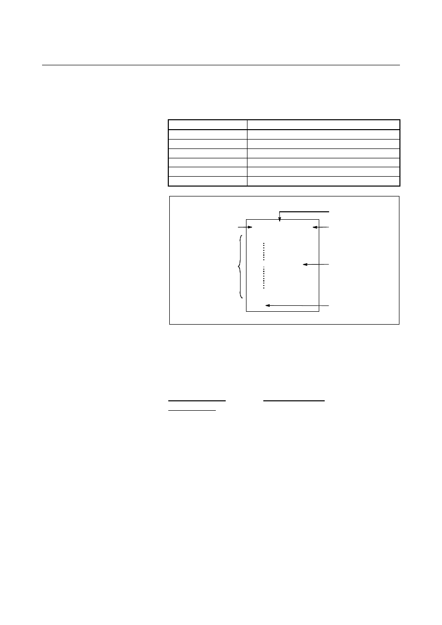
A program consists of the following components: 
 

Table 13 (a)    Program components 

Components Descriptions 

Program code start 

Symbol indicating the start of a program file 

Leader section 

Used for the title of a program file, etc. 

Program start 

Symbol indicating the start of a program 

Program section 

Commands for machining 

Comment section 

Comments or directions for the operator 

Program code end 

Symbol indicating the end of a program file 


Program code start

%

TITLE

;

O0001 ;

M30 ;

%

(COMMENT)

Program section

Leader section

Program start

Comment section

Program code end


Fig. 13 (b)    Program configuration 


  - Program section configuration 

A program section consists of several blocks. A program section starts 
with a program number or file name and ends with a program end 
code. 
 

Program section  

Program section  

configuration 

Program number   

O0001 ; 

Block 1   


N1 G91 G00 X120.0 Y80.0 ; 

Block 2   


N2 G43 Z-32.0 H01 ; 

    :                          : 
Block n   


Nn Z0 ; 

Program end  

M30 ; 

 
A block contains information necessary for machining, such as a move 
command or coolant on/off command.    Specifying a slash (/) at the 
start of a block disables the execution of some blocks (see "optional 
block skip" in II-13.2). 
 

B-63944EN/03

 PROGRAMMING 

13.PROGRAM CONFIGURATION


- 333 - 

13.1 

PROGRAM COMPONENTS OTHER THAN PROGRAM 
SECTIONS 

 
This section describes program components other than program 
sections. See II-13.2 for a program section. 

%

TITLE

;

O0001 ;

M30 ;

%

(COMMENT)

Program code start

Program section

Leader section

Program start

Comment section

Program code end


Fig. 13.1 (a)    Program configuration 


Explanation 
  - Program code start 

The program code start indicates the start of a file that contains NC 
programs. 
The mark is not required when programs are entered using SYSTEM 
P or ordinary personal computers. The mark is not displayed on the 
screen. However, if the file is output, the mark is automatically output 
at the start of the file. 
 

Table 13.1 (a)    Code of a program code start 

Name 

ISO code

EIA code 

Notation in this 

manual 

Program code start 

ER 


 - Leader section 

Data entered before the programs in a file constitutes a leader section.   
When machining is started, the label skip state is usually set by 
turning on the power or resetting the system. In the label skip state, all 
information is ignored until the first end-of-block code is read.  
When a file is read into the CNC unit from an I/O device, leader 
sections are skipped by the label skip function. 
A leader section generally contains information such as a file header. 
When a leader section is skipped, even a TV parity check is not made. 
So a leader section can contain any codes except the EOB code. 

13.PROGRAM CONFIGURATION

 PROGRAMMING 

B-63944EN/03


- 334 - 

 - Program start 

The program start code is to be entered immediately after a leader 
section, that is, immediately before a program section.   
This code indicates the start of a program, and is always required to 
disable the label skip function. 
With SYSTEM P or ordinary personal computers, this code can be 
entered by pressing the return key. 
 

Table 13.1 (b)    Code of a program start 

Name 

ISO code

EIA code 

Notation in this 

manual 

Program start 

LF 

CR 


NOTE 


If one file contains multiple programs, the EOB code 
for label skip operation must not appear before a 
second or subsequent program number.   


 - Comment section 

Any information enclosed by the control-out and control-in codes is 
regarded as a comment. 
The user can enter a header, comments, directions to the operator, etc. 
in a comment section. 
 

Table 13.1 (c)    Codes of a control-in and a control-out 

Name 

ISO code EIA code

Notation in this 

manual 

Meaning 

Control-out ( 

2-4-5  ( 

Start of comment 

section 

Control-in ) 

2-4-7  ) 

End of comment 

section 

When a program is read into memory for memory operation, comment 
sections, if any, are not ignored but are also read into memory. Note, 
however, that codes other than those listed in the code table in 
Appendix A are ignored, and thus are not read into memory. 
When data in memory is output on external I/O device (See III-8), the 
comment sections are also output. 
When a program is displayed on the screen, its comment sections are 
also displayed. However, those codes that were ignored when read 
into memory are not output or displayed. 
During memory operation or DNC operation, all comment sections are 
ignored. 
The TV check function can be used for a comment section by setting 
bit 1 (CTV) of parameter No. 0100. 
 

B-63944EN/03

 PROGRAMMING 

13.PROGRAM CONFIGURATION


- 335 - 

 CAUTION 


If a long comment section appears in the middle of 
a program section, a move along an axis may be 
suspended for a long time because of such a 
comment section. So a comment section should be 
placed where movement suspension may occur or 
no movement is involved. 


NOTE 

1  If only a control-in code is read with no matching 

control-out code, the read control-in code is 
ignored. 

2  The following codes cannot be used in the 

comment section: 
- EOB 
- % (ER for EIA) 


  - Program code end 

A program code end is to be placed at the end of a file containing NC 
programs. 
If programs are entered using the automatic programming system, the 
mark need not be entered.   
The mark is not displayed on the screen. However, when a file is 
output, the mark is automatically output at the end of the file. 
If an attempt is made to execute % when M02 or M30 is not placed at 
the end of the program, the alarm PS5010 is occurred. 
 

Table 13.1 (d)    Code of a program code end 

Name 

ISO code

EIA code 

Notation in this 

manual 

Program code end 

ER 


13.PROGRAM CONFIGURATION

 PROGRAMMING 

B-63944EN/03


- 336 - 

13.2 

PROGRAM SECTION CONFIGURATION 

 
This section describes elements of a program section.    See II-13.1 for 
program components other than program sections. 
 

%

(COMMENT)

%

TITLE  ;

O0001 ;

N1 ... ;

M30 ;

Program section

Program number

Sequence number

Program end


Fig. 13.2 (a)    Program configuration 


 - Program number 

A program number consisting of address O followed by a four-digit 
number is assigned to each program at the beginning registered in 
memory to identify the program.    When the 8-digit number function 
is selected, the program number consists of eight digits. 
In ISO code, the colon ( : ) can be used instead of O. 
When no program number is specified at the start of a program, the 
sequence number (N....) at the start of the program is regarded as its 
program number.    If a five-digit sequence number is used, the lower 
four digits are registered as a program number. If the lower four digits 
are all 0, the program number registered immediately before added to 
1 is registered as a program number.    Note, however, that N0 cannot 
be used for a program number. 
If there is no program number or sequence number at the start of a 
program, a program number must be specified using the MDI panel 
when the program is stored in memory (See III-8.2 or III-9.1) 
 

NOTE 


Program numbers 8000 to 9999 may be used by 
machine tool builders, and the user may not be able 
to use these numbers. 


B-63944EN/03

 PROGRAMMING 

13.PROGRAM CONFIGURATION


- 337 - 

 - File name 

A file name can be assigned instead of a program number. 
When coding a file name, be sure to place the file name enclosed in 
"<" and ">" at the beginning of a program. 
Example) % ; 

 <PARTS_1> 

 N1 

... 


 M30 

 % 


NOTE 


A file name can be coded: 

-  At the beginning of a program 
-  Immediately after M98, G65, G66, G66.1, M96, 

G72.1, or G72.2 


Do not code a file name in other than the above. 


  - Sequence number and block 

A program consists of several commands. One command unit is called 
a block.    One block is separated from another with an EOB of end of 
block code. 
 

Table 13.2 (a)    EOB code 

Name 

ISO code

EIA code

Notation in this manual

End of block (EOB) 

LF 

CR 

 
At the head of a block, a sequence number consisting of address N 
followed by a number not longer than eight digits (1 to 99999999) can 
be placed. Sequence numbers can be specified in a random order, and 
any numbers can be skipped.  Sequence numbers may be specified 
for all blocks or only for desired blocks of the program.    In general, 
however, it is convenient to assign sequence numbers in ascending 
order in phase with the machining steps (for example, when a new tool 
is used by tool replacement, and machining proceeds to a new surface 
with table indexing.) 
 

N300X200.0Z300.0 ;  A sequence number is underlined. 

Fig. 13.2 (b)    Sequence number and block (example) 


NOTE 


N0 must not be used for the reason of file 
compatibility with other CNC systems. 


Program number 0 cannot be used.    So 0 must 
not be used for a sequence number regarded as a 
program number. 


13.PROGRAM CONFIGURATION

 PROGRAMMING 

B-63944EN/03


- 338 - 

  - TV check (Vertical parity check) 

A parity check is made for each block of input data. If the number of 
characters in one block (starting with the code immediately after an 
EOB and ending with the next EOB) is odd, a P/S alarm (No.002) is 
output.   
No TV check is made only for those parts that are skipped by the label 
skip function.    Bit 1 (CTV) of parameter No. 0100 is used to specify 
whether comments enclosed in parentheses are counted as characters 
during TV check.    The TV check function can be enabled or disabled 
by setting on the MDI unit (See III-12.3.1.). 
 

  - Block configuration (word and address) 

A block consists of one or more words.  A word consists of an 
address followed by a number some digits long. (The plus sign (+) or 
minus sign (-) may be prefixed to a number.) 
For an address, one of the letters (A to Z) is used ; an address defines 
the meaning of a number that follows the address.     
 

Word = Address + number (Example : X-1000) 

Table 13.2 (b) indicates the usable addresses and their meanings. 
The same address may have different meanings, depending on the 
preparatory function specification. 
 

Table 13.2 (b)    Major functions and addresses 

Function Address 

Meaning 

Program number 

O

(*)

 Program 

number 

Sequence number 

Sequence number 

Preparatory function 

Specifies a motion mode (linear, 
arc, etc.) 

X, Y, Z, U, V, 

W, A, B, C 

Coordinate axis move command 

I, J, K 

Coordinate of the arc center 

Dimension word 

R Arc 

radius 

Feed function 

Rate of feed per minute,   
Rate of feed per revolution 

Spindle speed function

Spindle speed 

Tool function 

Tool number 

On/off control on the machine tool 

Auxiliary function 

Table indexing, etc. 

Program number 
designation 

P Subprogram 

number 

Number of repetitions

P, L 

Number of subprogram repetitions 

Parameter 

P, Q 

Canned cycle parameter 


M


Offset number 

D, H 

Offset number 

Dwell 

P, X 

Dwell time 


T


Dwell 

P, X, U 

Dwell time 


B-63944EN/03

 PROGRAMMING 

13.PROGRAM CONFIGURATION


- 339 - 

NOTE 

(*) In ISO code, the colon ( : ) can also be used as the 

address of a program number. 


N_ 

G_ 

X_  Y_ 

F_ 

S_ 

 T_ 

M_ 

;

Sequence 
number 

Preparatory 
function 

Dimension 
word 

Feed-functi
on 

Spindle 
speed 
function 

 Tool 

function 

Auxiliary 
function 

Fig. 13.2 (c)    1 block (example) 


  - Major addresses and ranges of command values 

Major addresses and the ranges of values specified for the addresses 
are shown below. Note that these figures represent limits on the CNC 
side, which are totally different from limits on the machine tool side. 
For example, the CNC allows a tool to traverse up to about 100 m (in 
millimeter input) along the X axis. 
However, an actual stroke along the X axis may be limited to 2 m for 
a specific machine tool. 
Similarly, the CNC may be able to control a cutting feedrate of up to 
240 m/min, but the machine tool may not allow more than 3 m/min. 
When developing a program, the user should carefully read the 
manuals of the machine tool as well as this manual to be familiar with 
the restrictions on programming. 
 

Table 13.2 (c)      Major addresses and ranges of command values 

Function 

Address 

Input in mm 

Input in inch


Program number 

O

 (*1)


1 to 99999999 

1 to 99999999 

Sequence number 

1 to 99999999 

1 to 99999999 

Preparatory function 

0 to 99.9 

0 to 99.9 

Increment system IS-A 

±

999999.99 mm 

±

999999.99 deg. 

±

99999.999 inch

 *3


±

999999.99 deg. 

Increment system IS-B 

±

999999.999 mm 

±

999999.999 deg. 

±

99999.9999 inch

 *3


±

999999.999 deg. 

Increment system IS-C 

±

99999.9999 mm 

±

99999.9999 deg. 

±

9999.99999 inch

 *3


±

99999.9999 deg. 

Increment system IS-D 

±

9999.99999 mm 

±

9999.99999 deg. 

±

999.999999 inch

 *3


±

9999.99999 deg. 

Dimension 
word 

Increment system IS-E 

X,Y,Z,U,V,
W,A,B,C,I,J
,K,R 

(*2)


±

999.999999 mm 

±

999.999999 deg. 

±

99.9999999 inch

 *3


±

999.999999 deg. 

Increment system IS-A 

0.01 to 999000.00mm/min 

0.001 to 96000.000inch/min 

Increment system IS-B 

0.001 to 999000.000mm/min 

0.0001 to 9600.0000inch/min 

Increment system IS-C 

0.0001 to 99999.9999mm/min 

0.00001 to 4000.00000inch/min 

Increment system IS-D 

0.00001 to 9999.99999mm/min 

0.000001 to 400.000000inch/min 

Feed per 
minute 

Increment system IS-E 

0.000001 to 999.999999mm/min

0.0000001 to 40.0000000inch/min

Feed per revolution 

0.001 to 50000mm/rev 

0.0001 to 50.0000inch/rev 

Spindle speed function 

(*4)


0 to 99999999 

0 to 99999999 

Tool function 

(*4)


0 to 99999999 

0 to 99999999 

(*4)


0 to 99999999 

0 to 99999999 

Auxiliary function 

(*4)


0 to 99999999 

0 to 99999999 

Offset number (M series only) 

H, D 

0 to 999 

0 to 999 


Content      ..     45      46      47      48     ..