FANUC Series 30i/300i/300is-MODEL A. Machining Center System. User's manual - page 31
 

  Index      Manuals     FANUC Series 30i/300i/300is-MODEL A. Machining Center System. User's manual (B-63944EN/03)


Search            copyright infringement  


Content      ..     29      30      31      32     ..


FANUC Series 30i/300i/300is-MODEL A. Machining Center System. User's manual - page 31


7.COORDINATE SYSTEM

 PROGRAMMING 

B-63944EN/03


- 204 - 

7.2.7 

Workpiece Coordinate System Shift 


T


Explanation 

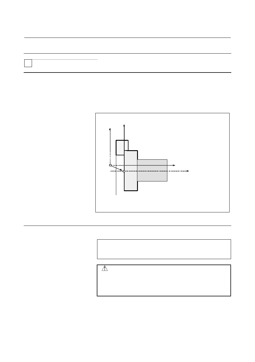
When the coordinate system actually set by the G50 command or the 
automatic system setting deviates from the programmed workpiece 
system, the set coordinate system can be shifted (see III-3.1). 
Set the desired shift amount in the workpiece coordinate system shift 
memory. 
 

Z

X

z

x

X-Z : Coordinate system in programming
x-z : Current set coordinate system with shift amount 0

(coordinate system to be modified by shifting)

O

O’

Set the shift amount from O' to O in the workpiece coordinate system shift memory.

Shift


Fig. 7.2.7 (a)      Workpiece coordinate system shift 


Format 
  - Changing the workpiece coordinate system shift amount 

G10 P0 

IP

_; 

IP

  : Settings of an axis address and a workpiece coordinate 

system shift amount 


 CAUTION 


A single block can contain a combination of X, Y, Z, 
C, U, V, W, and H (in G code system A).    In this 
case, if commands are specified for the same axis, 
whichever appears later becomes valid. 


B-63944EN/03

 PROGRAMMING 

7.COORDINATE SYSTEM


- 205 - 

Limitation 
  - Shift amount and coordinate system setting command 

Specifying a coordinate system setting command (G50 or G92) 
invalidates the shift amount that has already been set. 
Example) 
 

When G50X100.0Z80.0; is specified, a coordinate system is set 
so that the current base position of the tool is at X =100.0 and Z 
= 80.0, regardless of which value has been set for the workpiece 
coordinate system shift amount. 


  - Shift amount and coordinate system setting 

After a shift amount is set, when automatic coordinate system setting 
is performed upon manual reference position return, the set coordinate 
system is immediately shifted by the set amount. 
 

  - Diameter and radius values 

The workpiece coordinate system shift amount depends on diameter 
programming or radius programming. 
 
Example) 
 

Although the base point should be positioned at X = 

φ

120.0 

(diameter value) and Z = 70.0 from the workpiece origin, the 
actual position is at X = 

φ

121.0 and Z = 69.0 from the origin.  

Set a shift amount as shown below: 

 X=1.0, 

Z=-1.0 

Z

X

69.0

Start point = base
point

φ

121.

0


7.COORDINATE SYSTEM

 PROGRAMMING 

B-63944EN/03


- 206 - 

7.3 

LOCAL COORDINATE SYSTEM 

 
When a program is created in a workpiece coordinate system, a child 
workpiece coordinate system can be set for easier programming.  
Such a child coordinate system is referred to as a local coordinate 
system. 
 

Format 

G52 

IP

_; 

Setting the local coordinate system


      : 
G52 

IP

 0 ; 

Canceling of the local coordinate system


IP

_  : Origin of the local coordinate system 


Explanation 

By specifying G52 IP_;, a local coordinate system can be set in all the 
workpiece coordinate systems (G54 to G59).  The origin of each 
local coordinate system is set at the position specified by IP_ in the 
workpiece coordinate system. 
Once a local coordinate system is established, the coordinates in the 
local coordinate system are used in an axis shift command.    The local 
coordinate system can be changed by specifying the G52 command 
with the origin of a new local coordinate system in the workpiece 
coordinate system.   
To cancel the local coordinate system or specify the coordinate value 
in the workpiece coordinate system, match the origin of the local 
coordinate system with that of the workpiece coordinate system. 
 

(Local coordinate system)

(Local coordinate system)

(Machine coordinate system)

Machine coordinate system zero point

Reference position

(G59: Workpiece coordinate

system 6)

(G54:  Workpiece coordinate system 1)

G55

G56

G57

G58

IP

_

IP

_


Fig. 7.3 (a)    Setting the local coordinate system 

B-63944EN/03

 PROGRAMMING 

7.COORDINATE SYSTEM


- 207 - 

 CAUTION 

1  When ZCL (bit 2 of parameter No.1201) is set to 1 

and an axis returns to the reference position by the 
manual reference position return function, the 
origin of the local coordinate system of the axis 
matches that of the workpiece coordinate system.   
The same is true when the following command is 
issued: 


    G52

α

0; 


α

:    Axis which returns to the reference position 

2  The local coordinate system setting does not 

change the workpiece and machine coordinate 
systems. 

3  Whether the local coordinate system is canceled at 

reset depends on the parameter setting.    The local 
coordinate system is canceled when either bit 6 
(CLR) of parameter No.3402 or bit 3 (RLC) of 
parameter No.1202 is set to 1.    In 
three-dimensional coordinate conversion mode, 
however, the local coordinate system is not 
canceled when bit 2 (D3R) of parameter No. 5400 
is set to 1. 

4  When a workpiece coordinate system is set with 

the G92 (G50 for G code system A in the T series) 
command, the local coordinate system is canceled.   
However, the local coordinate system of an axis for 
which no coordinate system is specified in a G92 
(G50 for G code system A in the T series) block 
remains unchanged. 

5  G52 cancels the offset temporarily in tool radius 


tool nose radius compensation. 

6  Command a move command immediately after the 

G52 block in the absolute mode. 


7.COORDINATE SYSTEM

 PROGRAMMING 

B-63944EN/03


- 208 - 

7.4 

PLANE SELECTION 

 
Select the planes for circular interpolation, cutter compensation, and 
drilling by G-code. 
The following table lists G-codes and the planes selected by them. 
 

Explanation 

Table 7.4 (a)    Plane selected by G code 

G code 

Selected plane

Xp 

Yp 

Zp 

G17 

Xp Yp plane 

G18 

Zp Xp plane 

G19 

Yp Zp plane 

X-axis or an 

axis parallel to 

it 

Y-axis or an 

axis parallel to 

it 

Z-axis or an 

axis parallel to 

it 

Xp, Yp, Zp are determined by the axis address appeared in the block 
in which G17, G18 or G19 is commanded. 
When an axis address is omitted in G17, G18 or G19 block, it is 
assumed that the addresses of basic three axes are omitted. 
Parameter No. 1022 is used to specify that an optional axis be parallel 
to the each axis of the X-, Y-, and Z-axes as the basic three axes. 
The plane is unchanged in the block in which G17, G18 or G19 is not 
commanded. 
The movement instruction is irrelevant to the plane selection. 

M


When the power is turned on or the CNC is reset, G17 (XY plane), 
G18 (ZX plane), or G19 (YZ plane) is selected by bits 1 (G18) and 2 
(G19) of parameter No. 3402). 
 

T


When the power is turned on, G18 (ZX plane) is selected. 

NOTE 


U-, V-, and W-axes can be used with G-codes B 
and C. 


Example 

Plane selection when the X-axis is parallel with the U-axis.   
 G17X_Y_ XY 

plane, 


 G17U_Y_ UY 

plane 

 G18X_Z_ ZX 

plane 


      X_Y_ 

Plane is unchanged (ZX plane) 

 G17 

  XY 

plane 

 G18 


  ZX 

plane 


G17 U_ 

UY plane 


G18Y_ ; 

ZX plane, Y axis moves regardless without any 


relation to the plane. 

B-63944EN/03

 PROGRAMMING 

8.COORDINATE VALUE AND DIMENSION


- 209 - 

COORDINATE VALUE AND DIMENSION 

 
Chapter 8, "COORDINATE VALUE AND DIMENSION", consists 
of the following sections: 
 
8.1  ABSOLUTE AND INCREMENTAL PROGRAMMING .......210 
8.2  INCH/METRIC CONVERSION (G20, G21)...........................212 
8.3  DECIMAL POINT PROGRAMMING ....................................216 
8.4  DIAMETER AND RADIUS PROGRAMMING .....................218 
8.5  DYNAMIC SWITCHING OF DIAMETER/RADIUS 

SPECIFICATION .....................................................................219 


8.COORDINATE VALUE AND DIMENSION

 PROGRAMMING 

B-63944EN/03


- 210 - 

8.1 

ABSOLUTE AND INCREMENTAL PROGRAMMING 

 
There are two ways to command travels of the tool; the absolute 
programming, and the incremental programming. In the absolute 
programming, coordinate value of the end position is programmed. 
The incremental programming is used to program the amount of a tool 
movement. 
 

M


G90 and G91 are used to programming absolute or incremental 
programming, respectively. 
 

T


Absolute programming or incremental programming is used 
depending on the programming used. See following tables. 

G code system 

B or C 

Command method 

Address word 

G90, G91 


Format 

M


Absolute programming

 G90 

IP_ 

Incremental programming

 G91 

IP_ 


T


  - G code system A 


Absolute 

programming 

Incremental 

programming 

X axis move command

X   

U   

Z axis move command

Z   

W   

Y axis move command

Y   

V   

C axis move command

C   

H   


  - G code system B or C 

Absolute programming

 G90 

IP_ 

Incremental programming

 G91 

IP_ 


B-63944EN/03

 PROGRAMMING 

8.COORDINATE VALUE AND DIMENSION


- 211 - 

Example 

M


Absolute programming 

Incremental programming 

G90 X40.0 Y70.0 ;

G91 X-60.0 Y40.0 ;

Y

70.0

30.0

40.0

100.0 

End point 

Start point 


T


Tool movement from point P to point Q (diameter programming is 
used for the X-axis) 


G code system A 

G code system B or C

Absolute programming

X400.0 Z50.0 ; 

G90 X400.0 Z50.0 ; 

Incremental 

programming 

U200.0 W-400.0 ; 

G91 X200.0 Z-400.0 ; 


φ

400

φ

200

50

450

P

(200, 450)

Q

(400, 50)

Z

X


NOTE 

1  Absolute programming and incremental 

programming can be used together in a block. 


In the above example, the following command can 
be specified : X400.0 W-400.0 ; (in the G code 
system A) 

2  When both X and U or Z and W are used together 

in a block, the one specified later is effective. 

3  Incremental programming cannot be used when 

names of the axes are A and B during G code 
system A is selected. 


Content      ..     29      30      31      32     ..