FANUC Robot M-710iC MECHANICAL UNIT. OPERATOR'S MANUAL (B-82274EN/09) - page 4
B-82274EN/09
6.AXIS LIMIT SETUP
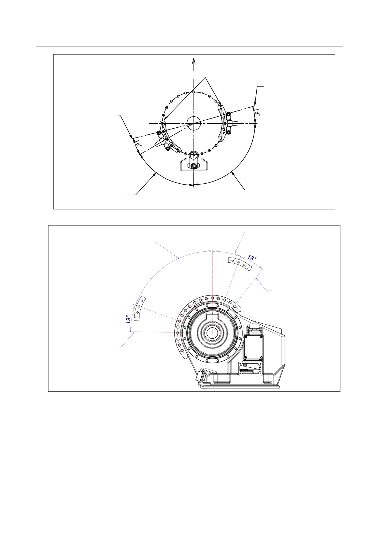
Front of robot
J1 movable stopper
The maximum stopping
distance (position)
The maximum stopping
distance (position)
Specified motion range
Specified motion range
or minus side
of plus side
Fig. 6.2(g) The maximum stopping distance of movable mechanical stopper(J1-axis of M-710iC/70)
Specified motion range
of minus side
Specified motion range
of plus side
The maximum stopping
distance (position)
The maximum stopping
distance (position)
Fig. 6.2(h) The maximum stopping distance of movable mechanical stopper
(J2-axis of M-710iC/50, /50H, /50E)
- 71 -
6.AXIS LIMIT SETUP
B-82274EN/09
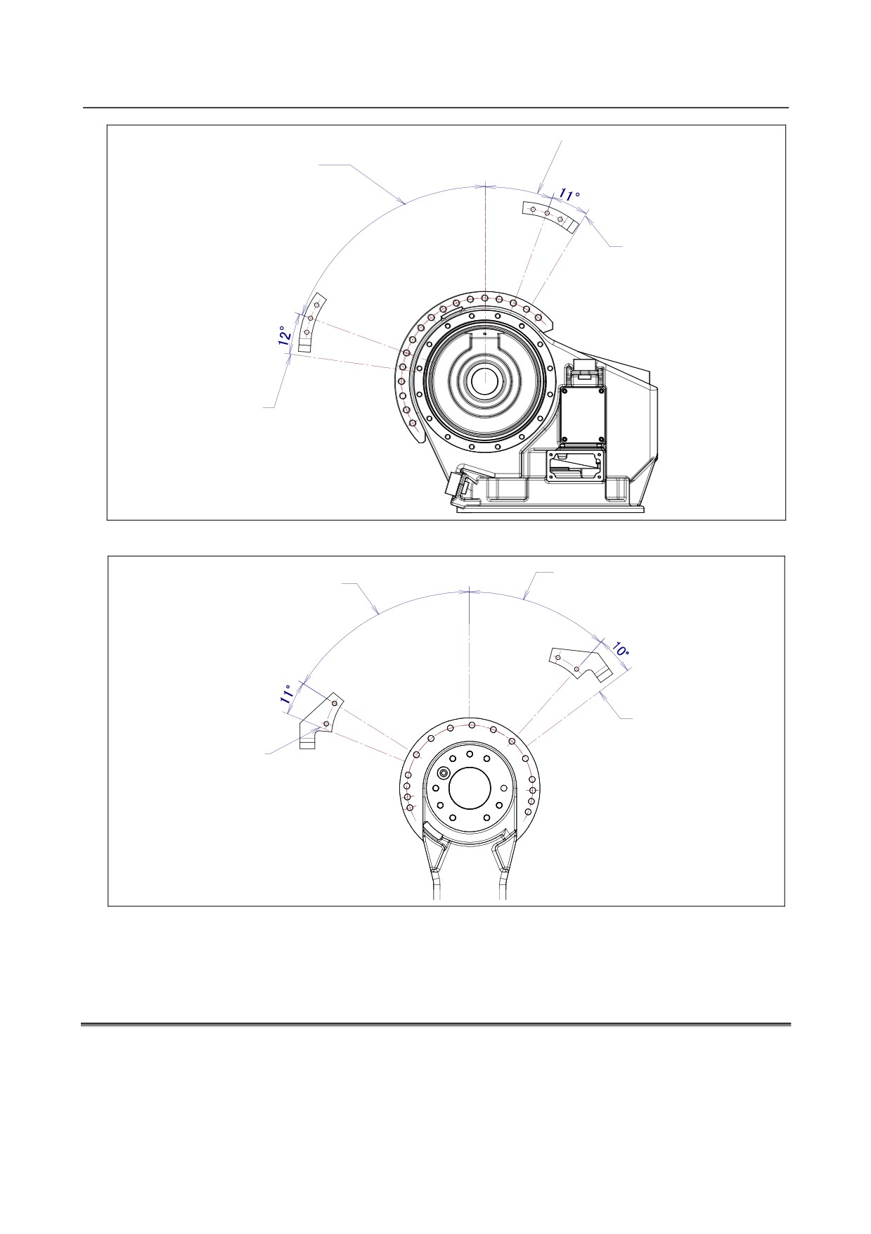
Specified motion range
of minus side
Specified motion range
of plus side
The maximum stopping
distance (position)
The maximum stopping
distance (position)
Fig. 6.2(i) The maximum stopping distance of movable mechanical stopper(J2-axis of M-710iC/70)
Specified motion range
Specified motion range
of minus side
of plus side
The maximum stopping
distance (position)
The maximum stopping
distance (positon)
Fig. 6.2(j) The maximum stopping distance of movable mechanical stopper
(J3-axis of M-710iC/50, /70, /50H ,/50E)
6.3
CHANGING THE MOTION RANGE BY THE LIMIT SWITCH
(OPTION)
The limit switch is an over travel switch, which interrupts power to the servo motor and stops the robot
when turned on. The limit switch is optionally provided for the J1-axis.
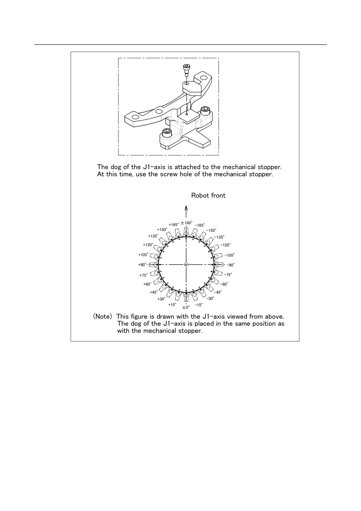
To change the motion range by the limit switch, move the dog. The following figure shows the
relationship between the dog position and the motion range.
The dog of the J1-axis is placed in the same position as with the mechanical stopper.
- 72 -
B-82274EN/09
6.AXIS LIMIT SETUP
Fig. 6.3 J1-Axis Dog Position and Motion Range (Option)
- 73 -
6.AXIS LIMIT SETUP
B-82274EN/09
6.4
ADJUSTING LIMIT SWITCH (OPTION)
After the motion range is changed by the limit switch, be sure to make adjustment.
ADJUSTING PROCEDURE
1
Set the $MOR_GRP.$CAL_DONE system parameter to FALSE. This disables the motion limit
specified by the software. As a result, the operator can rotate the robot by a jog feed which goes
beyond the motion limit.
2
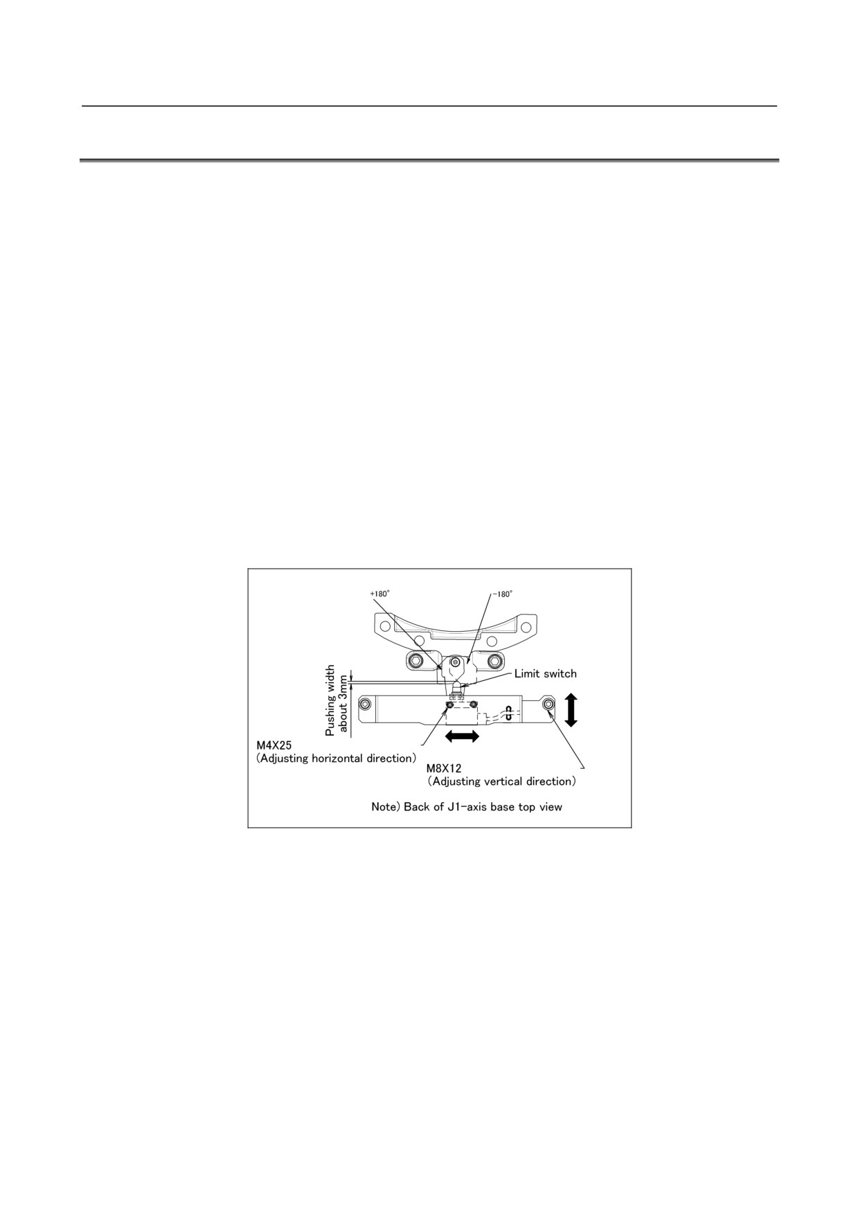
Loosen the following bolts.
M8×12
2 pcs M4×25
2 pcs
3
Move the limit switch so that the robot activates it at about 1.0° degree before the stroke end. Step
on the dog, and position the limit switch in such a place that only one of the step-on allowance
indication lines at the tip of the switch is hidden.
4
When the limit switch operates and detects overtravel (OT), the robot stops, and an error message,
“OVERTRAVEL”, is displayed. To restart the robot, hold on the SHIFT key and press the RESET
key. Then, while holding on the SHIFT key, move the adjusting axis off the OT limit switch by
jogging in joint mode.
5
Check that the robot also activates the limit switch when the robot is approx. 1.0° degrees from the
opposite stroke end in the same way as above. If the limit switch does not operate at the position,
adjust the position of the switch again.
6
Set the $MOR_GRP.$CAL_DONE system parameter to TRUE.
7
Turn off the power, then turn it on again to restart the controller.
Fig. 6.4 Adjusting J1-axis limit switch (option)
- 74 -

B-82274EN/09
7.CHECKS AND MAINTENANCE
7 CHECKS AND MAINTENANCE
Optimum performance of the robot can be maintained by performing the periodic maintenance procedures
presented in this chapter.(See the Appendix A PERIODIC MAINTENANCE TABLE.)
NOTE
The periodic maintenance procedures described in this chapter assume that the
FANUC robot is used for up to 3840 hours a year. When using the robot
beyond this total operating time, correct the maintenance frequencies shown in
this chapter by calculation in proportion to the difference between the actual
operating time and 3840 hours/year.
7.1
PERIODIC MAINTENANCE
7.1.1
Daily Checks
Clean each part, and visually check component parts for damage before daily system operation. Check the
following items as the occasion demands.
(1) Before turning on power
Item
Check items
Check points
1
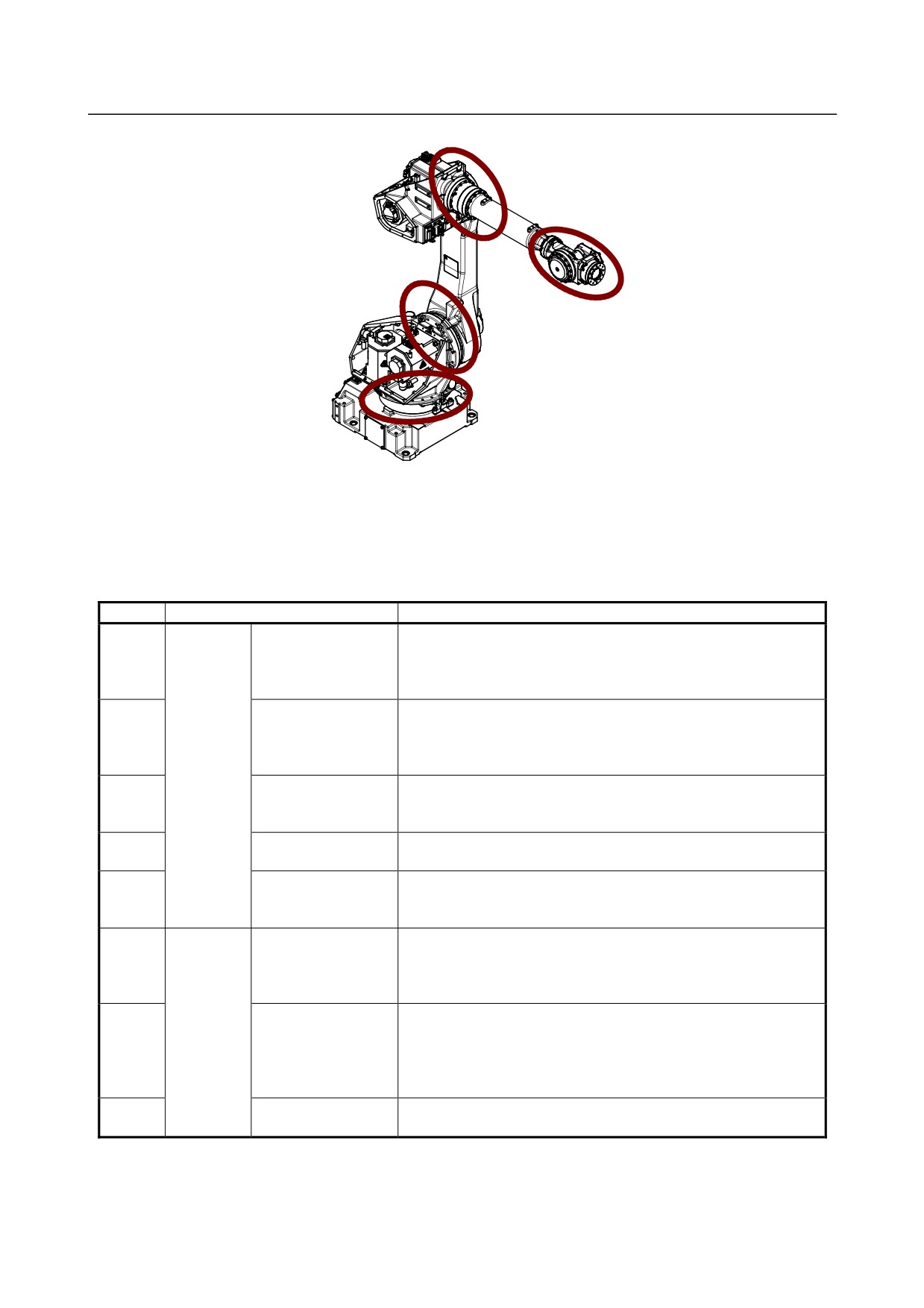
Oil exudation
Check there is oil exudation on sealed part of each joint parts.
NOTE
1 Oil exudation may be attached (Slightly a loot oil stick) to outside of lip depend
on the movement condition or environment of the circumference. If this oil
contents change to a state of dew, it may fail depend on the movement.
You can prevent oil spot from falling down by wiping the oil contents which is
accumulated to under part of oil seal before operation.
2 Also, motors may become the high temperature and the internal pressure of
grease bath may rise by frequent repetition movement and use in the high
temperature environment.
In these cases, you can return internal pressure by releasing grease out let just
after operation of robot. (When opening grease outlet, pay attention grease is
not scattered referring to Subsection 7.2.2.)
- 75 -
7.CHECKS AND MAINTENANCE
B-82274EN/09
Fig.7.1.1 (a) Check parts of oil exudation
Check items
Wipe off the oil contents of each joint part which has oil seal.
When air control set is combined
Item
Check items
Check points
1
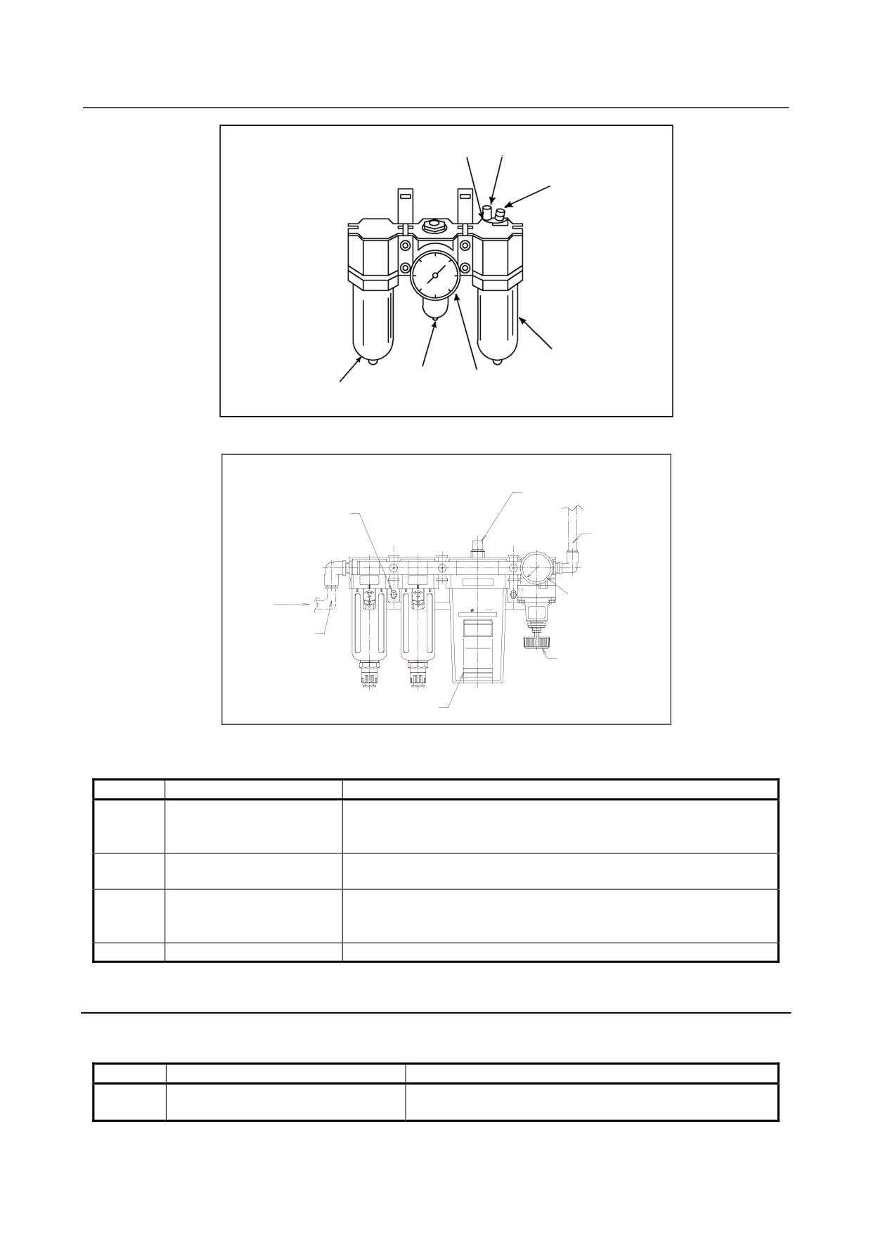
Air pressure
Check air pressure using the pressure gauge on the air regulator
as shown in Fig.7.1.1 (a). If it does not meet the specified pressure
of 0.49 to 0.69 MPa (5-7 kgf/cm2), adjust it using the regulator
pressure-setting handle.
2
Lubricator oil mist
Check the drop quantity during wrist or hand motion. If it does not
quantity
meet the specified value (1 drop/10-20 sec), adjust it using the
lubricator control knob. Under normal usage, the lubricator
In case of
becomes empty in about 10 to 20 days under normal operation.
air control
3
Lubricator oil level
Check to see that the lubricator level is within the specified level
set
shown meet the specified pressure of 10 KPa (0.1kgf/cm2), adjust
it using the regulator pressure-setting handle.
4
Leakage from hose
Check the joints, tubes, etc. for leaks. Repair leaks, or replace
parts, as required.
5
Drain
Check drain and release it. When quantity of the drain is
remarkable, examine the setting of the air dryer to the air supply
side.
6
Supply pressure
Check the supply pressure using the air
purge kit shown in Fig.7.1.1 (b). If it does not
meet the specified pressure of 10 KPa (0.1
kgf/cm2), adjust it using the regulator pressure setting handle.
7
In case of
Dryer
Check whether the color of the dew point
air purge
checker is blue. When it is not blue, identify
kit
the cause and replace the dryer. Maintenance
for air purge kit, refer to the operator’s
manual attached kit.
8
Drain
Check drain, When quantity of the drain is remarkable, examine
the setting of the air dryer to the air supply side.
- 76 -
B-82274EN/09
7.CHECKS AND MAINTENANCE
Lubricator
Adjusting knob
Oil inlet
Lubricator
mist amount check
Lubricator
Regulator
Filter
Pressure
pressure
setting
Fig.7.1.1 (b) Air control set
Dew point checker
2-7x11
Length round hole
Air outlet
(O6 Air tube)
Pressure gauge
Pneumatic
air outlet
Air inlet
(O10 air tube)
Pressure adjustment knob
S
S
Dryer unit
Fig.7.1.1 (c) Air purge kit (option)
(2) After automatic operation
Item
Check items
Check points
1
Vibration, abnormal noises,
Check whether the robot moves along and about the axes smoothly
and motor heating
without unusual vibration or sounds. Also, check whether the
temperatures of the motors are excessively high.
2
Changing repeatability
Check to see that the stop positions of the robot have not deviated from
the previous stop positions.
3
Peripheral devices for
Check whether the peripheral devices operate properly according to
proper operation
commands
from the robot.
4
Brakes for each axis
Check that the end effector drops within 0.5 mm when the power is cut.
7.1.2
First 1-Month (320 hours operating) Check
Check the following items after the first one-month operation (or 320 hours operating)
Item
Check items
Check points
1
Ventilation portion of controller
If the ventilation portion of the controller is dusty, turn off
power and clean the unit.
- 77 -
7.CHECKS AND MAINTENANCE
B-82274EN/09
7.1.3
First 3-month (960 hours) Checks
Check the following items at the first quarterly inspection, then every year thereafter.(See the
Subsection 7.1.5.)
Item
Check items
Check points
1
Retightening external main bolts
Further, tighten the end-effecter mounting bolts and external
main bolts. (Note 1)
2
Check the mechanical stopper and
Check the looseness of mounting bolts of mechanical stopper
adjustable mechanical stopper
and adjustable
mechanical stopper. Particular, check swing stopper of
J1-axis rotates smoothly (Note 2)
3
Cleaning and checking each part
Clean each part (remove chips, etc.) and check component
parts for cracks and flaws.(Note 3)
4
Check the end effector (hand) cable
Confirm whether there is wound in the coating of cable
5
Check the fan.
Confirm whether the fan operates normally when fan is
attached,
6
Check the teach pendant cable,
Check whether the cable connected to the teach pendant and
operation box connecting cable and robot
robot is unevenly twisted.
connecting cable
Note 1) Points to be retightened
• The end effecter mounting bolts, robot installation bolts, and bolts to be removed for inspection need
to be retightened.
• The bolts exposed to the outside of the robot need to be retightened.
For the tightening torque, see the recommended bolt tightening torque shown in the Appendix.
A loose prevention agent (adhesive) is applied to some bolts. If the bolts are tightened with greater than
the recommended torque, the loose prevention agent may be removed. So, follow the recommended
tightening torque when retightening them.
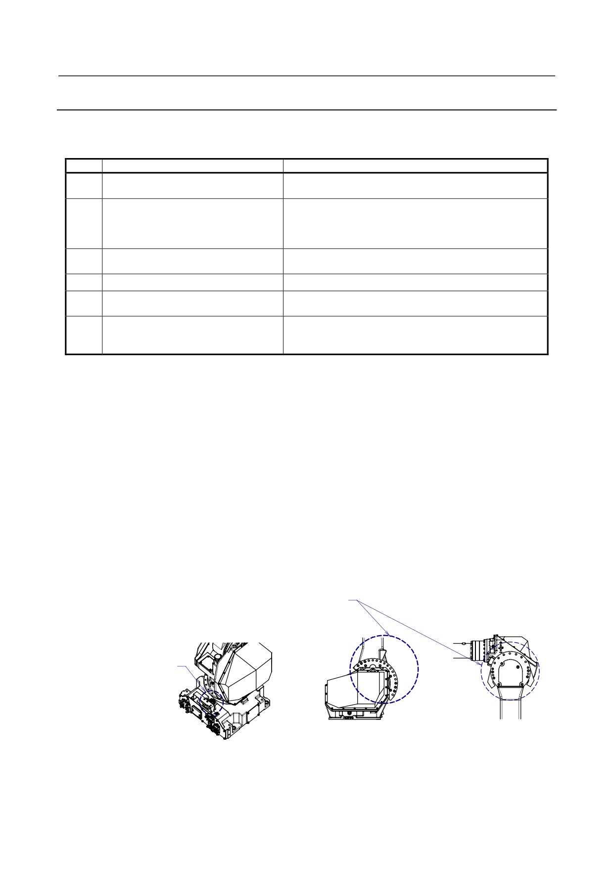
Note 2) Check of mechanical stopper and adjustable mechanical stopper.
-
Check the looseness of stopper mounting bolts. If they are loose, they are needed to be retightened.
Especially, check the looseness of mounting bolts of J1-axis swing stopper.
-
Check that J1-axis swing stopper rotates smoothly.
Check the looseness
of bolts.
Check the looseness of bolts
and stopper rotate smoothly.
Fig.7.1.3 (a) Check of mechanical stopper and adjustable mechanical stopper.
- 78 -
B-82274EN/09
7.CHECKS AND MAINTENANCE
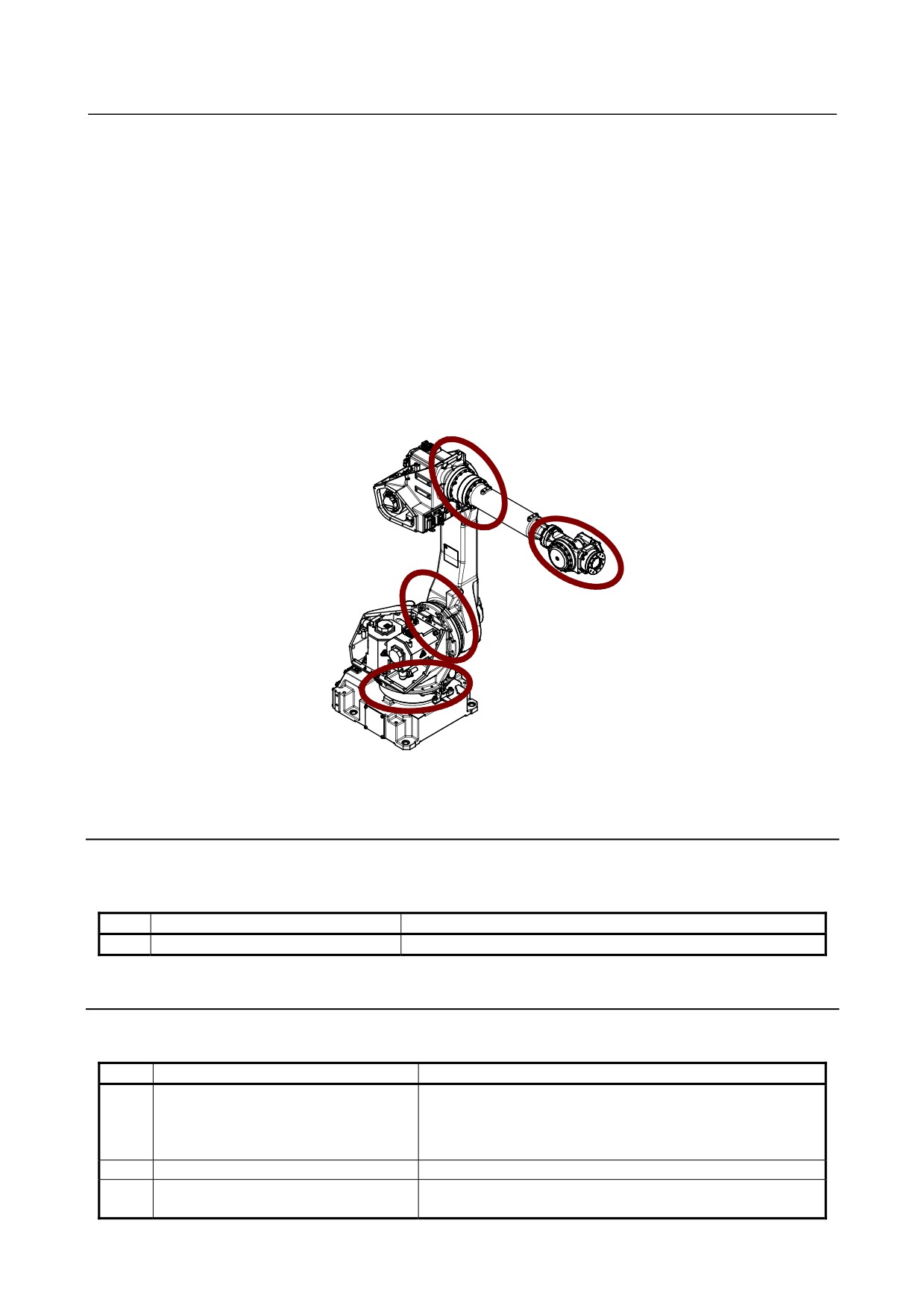
Note 3) Cleaning
• Necessary cleaning points, dust on the flat part, sedimentation of spatters
Clean sediments periodically. In particular, clean the following points carefully.
Vicinity of the wrist axis and oil seal
→ If chippings or spatters are attached to the oil seal, an oil leak may be caused.
• Check if the vicinity of the necessary inspection points, wrist part, and J3 arm significantly wears
due to rubbing against the welding cable or hand cable.
• Check if there is a trace of a collision around the gun or hand.
• Check the reducer or grease bath for an oil leak.
→ If oil can be found a day after wiping oil, an oil leak may be caused.
Vicinity of the welding torch and wrist flange (When ARC welding application is specified.)
→The insulation failure occurs when the spatter has collected around the wrist flange or welding torch,
and there is a possibility of damaging the robot mechanism by the welding current. (See Appendix C)
Fig.7.1.3 (b) Cleaning part
7.1.4
3-month (960 hours) Checks
Check the following item at the first one-months (320 hours), then every 3-month thereafter. (See the
Subsection 7.1.3.)
Item
Check items
Check points
1
Ventilation portion of controller
(See Section 7.1.2.)
7.1.5
1-year (3,840 hours) Checks
Check the following items about once every year (3,840 hours).
Item
Check items
Check points
1
Cables used in mechanical unit
Check whether the jackets of the mechanical unit cables are
damaged. Also, check whether the cables are excessively bent
or unevenly twisted. Check that the connectors of the motors
and connector panels are securely engaged.(Note 4)
2
Retightening external main bolts
(See Section 7.1.3.)
3
Check the mechanical stopper and
(See Section 7.1.3.)
adjustable mechanical stopper
- 79 -
7.CHECKS AND MAINTENANCE
B-82274EN/09
Item
Check items
Check points
4
Cleaning each parts and inspection
(See Section 7.1.3.)
5
Check the end effector (hand) cable
(See Section 7.1.3.)
6
Check the fan
(See Section 7.1.3.)
7
Check the teach pendant cable,
(See Section 7.1.3.)
operation box connecting cable and
robot connecting cable
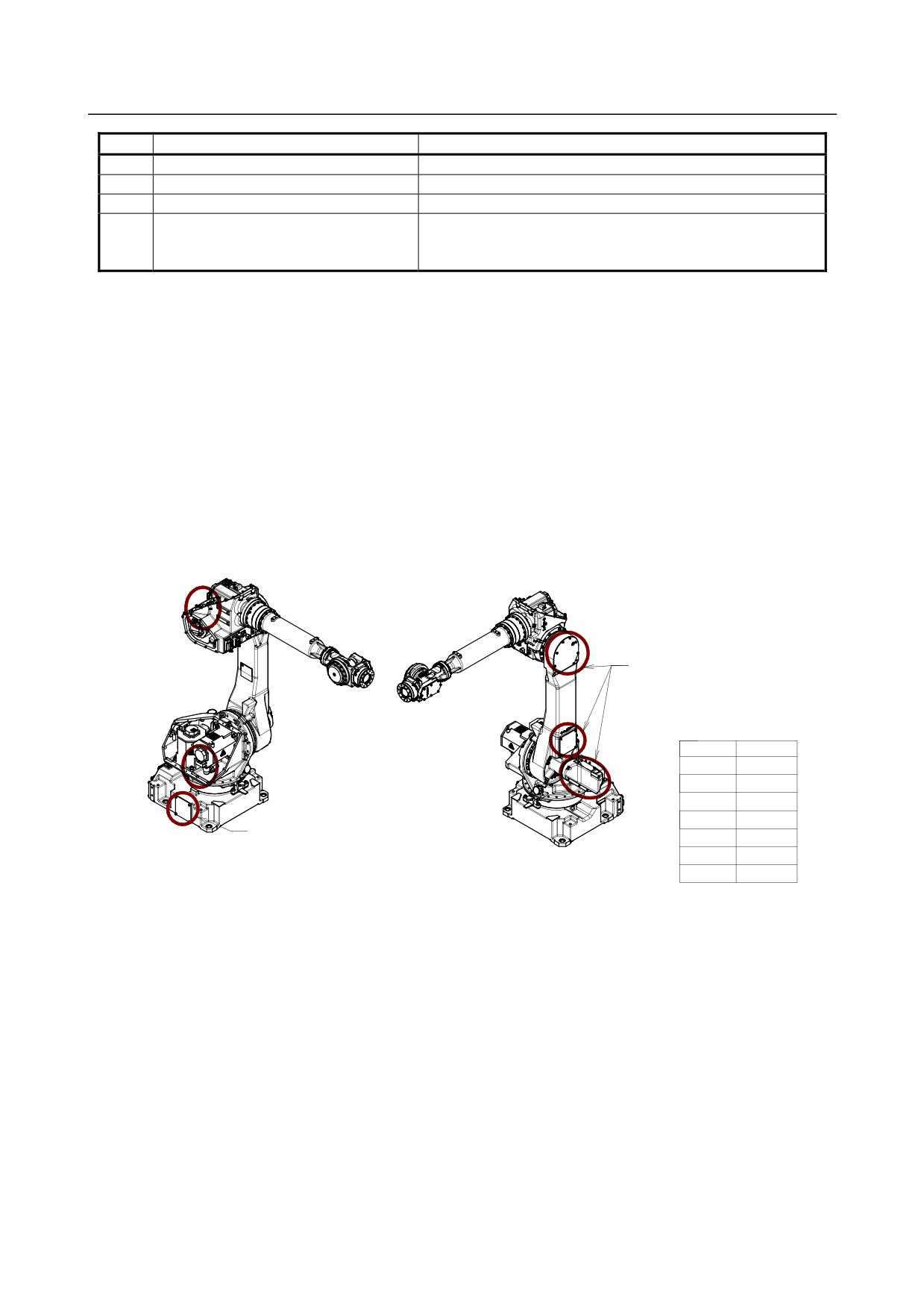
Note 1) Inspection points and check items of the mechanical unit cables and
connectors
Inspection points of the mechanical unit cables
For the J1-axis and J2-axis,check cables after remove J2 motor cover.
For the J3-axis,check cables after remove cover of J3 casing.
When severe dust/liquid protection option is selected, packing is attached to the cover. If you remove
covers, exchange packing for the new article absolutely.
Check items
For cables with a cable protection sheet, open the protection sheet before making the check.
Check the cables for a sheath break and wear.
If wires of the cable appear, replace it.
Please remove
these cover,too.
Spec. of gasket
(When severe dust/liquid
option is selected)
use part
spec
side of J1 base
A290-7125-X801
J1 motor cover
A290-7125-X806
side of J2 base
A290-7125-X805
below side of
A290-7125-X808
J2 arm
Please remove
upper side of
A290-7125-X809
J2 arm
this cover,too.
J3 motor cover
A290-7125-X810
side of J3 casing
A290-7125-X815
Fig 7.1.5 (a) Check items of Mechanical unit cable
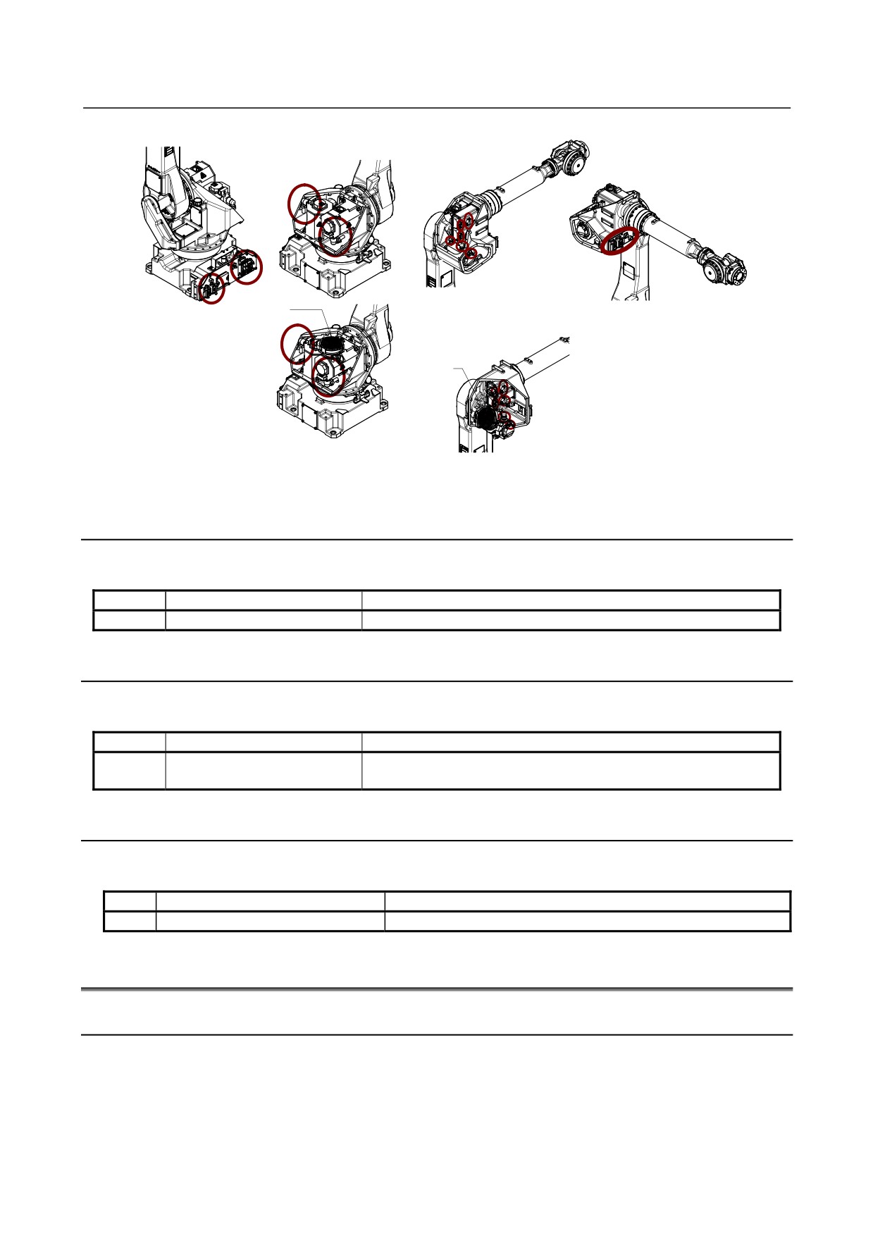
Inspection points of the connectors
•
Power/brake connectors of the motor
•
Robot connection cables and user cables
Check items
• Circular connector: Check the connector for looseness by turning it manually.
• Square connector: Check the connector for disengagement of its lever.
• Earth terminal: Check the connector for looseness.
When severe dust/liquid protection option is selected, packing is attached to the cover. If you remove
covers, exchange packing for the new article absolutely.
- 80 -
B-82274EN/09
7.CHECKS AND MAINTENANCE
Fan motor
Fan motor
M-710iC/50H
Fig 7.1.5 (b) Check items of connector
7.1.6
1.5-year (5,760 hours) Checks
Check the following item once every 1.5-year (5,760 hours).
Item
Check items
Check points
1
Battery
Replace battery in the mechanical unit. (See Section 7.2)
7.1.7
3-year (11,520 hours) Checks
Check the following items about once every 3 years (11,520 hours).
Item
Check items
Check points
1
Replacing grease of each axis
(See Section 7.2)
reducer and gearbox
7.1.8
4-year (15,360 hours) Checks
Check the following items once every 4 years (15,360 hours).
Item
Check items
Check points
1
Replace the mechanical unit cable
Contact FANUC about replacing method
7.2
MAINTENANCE
7.2.1
Replacing the Batteries (1.5 Years checks)
The position data of each axis is preserved by the backup batteries. The batteries need to be replaced
every 1.5 years. Also, use the following procedure to replace when the backup battery voltage drop alarm
occurs.
- 81 -
7.CHECKS AND MAINTENANCE
B-82274EN/09
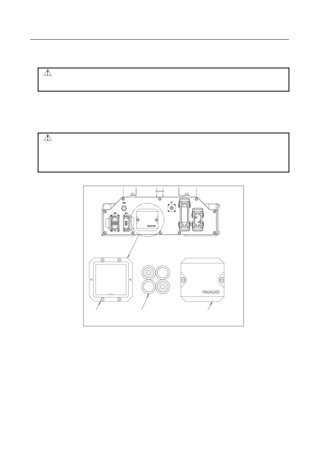
Procedure of replacing the battery
1
Keep the power on. Press the EMERGENCY STOP button to prohibit the robot motion.
CAUTION
Replacing the batteries with the power supply turned off causes all current
position data to be lost. Therefore, mastering will be required again.
2
Remove the battery case cap.( Fig. 7.2.1 (a))
3
Take out the old batteries from the battery case.
4
Insert new batteries into the battery case. Pay attention to the direction of batteries.
5
Close the battery case cap.
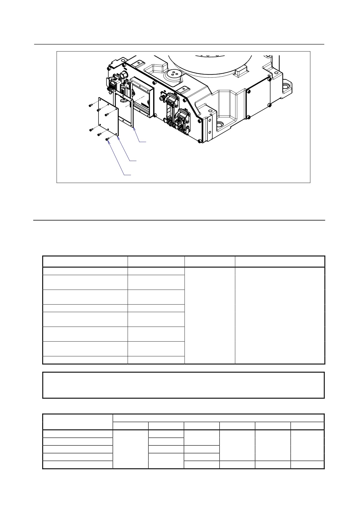
CAUTION
When using a robot with the severe dust/liquid protection option, remove the
cover from the battery case as shown in Fig. 7.2.1 (b) to replace the battery. After
replacing the battery, reinstall the cover. In this time, please be sure to replace
packing to new one for effects of severe dust/liquid protection.
Battery case
Battery
Case cap
(1.5V size D, 4pcs)
Fig. 7.2.1 (a) Replacing the battery
- 82 -
B-82274EN/09
7.CHECKS AND MAINTENANCE
Packing
A290-7125-X820
Plate
Seal bolt
Fig. 7.2.1 (b) Removing the plate
7.2.2
Replacing the Grease of the Drive Mechanism (3 years
(11,520 hours) checks)
Replace the grease of the reducers of J1, J2, and J3 axes, the J4-axis gearbox and the wrist every three
years or 11,520 hours by using the following procedures.
Table 7.2.2 (a) Grease for 3-year periodical replacement
Supply position
Quantity
Gun tip pressure
Grease name
J1-axis reducer
2950g (3300ml)
J2-axis reducer
1500g (1660ml)
(M-710iC/50, /70, /50S, /50E)
J2-axis reducer
1260g (1400ml)
(M-710iC/50H)
J3-axis reducer
950g(1060ml)
Kyodo Yushi
0.1MPa
J4/J5/J6-axis gearbox
VIGOGREASE RE0
810g (920ml)
or less (NOTE)
(M-710iC/50, /70, /50S, /50E)
Spec.:A98L-0040-0174
J4/J5-axis gearbox
580g (650ml)
(M-710iC/50H)
Wrist
580g (650ml)
(M-710iC/50, /70 ,/50H, 50S)
Wrist (M-710iC/50E)
510g (580ml)
NOTE
When using a hand pump, apply grease approximately once per two seconds. For
grease replacement or replenishment, use the postures indicated below.
Table 7.2.2 (b) Postures for greasing
Posture
Supply position
J1
J2
J3
J4
J5
J6
J1-axis reducer
Arbitrary
Arbitrary
J2-axis reducer
0°
Arbitrary
Arbitrary
Arbitrary
J3-axis reducer
Arbitrary
0°
0°
J4-axis gearbox
0°
Arbitrary
Wrist
0°
0°
0°
0°
- 83 -
7.CHECKS AND MAINTENANCE
B-82274EN/09
CAUTION
If greasing is performed incorrectly, the internal pressure of the grease bath may
suddenly increase, possibly causing damage to the seal, which would in turn
lead to grease leakage and abnormal operation. When performing greasing,
therefore, observe the following cautions.
1 Before starting to grease, open the grease outlet (remove the plug or bolt from
the grease outlet).
2 A grease inlet may optionally have a plug. Replace the plug with the attached
grease nipple and then start greasing.
3 A grease inlet may optionally have a plug. Replace the plug with the attached
grease nipple and then start greasing.
4 Whenever possible, avoid using an air pump, which is powered by the factory air
supply.
If the use of an air pump is unavoidable, supply grease with the pump at a
pressure lower than or equal to the gun tip pressure (see Table 7.2.3 (a)).
5 Use grease only of the specified type. Grease of a type other than that specified
may damage the reducer or lead to other problems.
6 After greasing, release remaining pressure from the grease bath using the
procedure given in Section 7.2.6, and then close the grease outlet.
7 To prevent accidents caused by slipping, completely remove any excess grease
from the floor or robot.
7.2.3
Grease Replacement Procedure of the J1, J2, J3-Axis
Reducer
1
Move the robot to the greasing posture described in Table 7.2.2 (b).
2
Turn off the controller power.
3
Remove the seal bolt from grease outlet.(Fig.7.2.3 (a)~7.2.3 (d))
4
Supply new grease through the grease inlet until new grease is output from grease outlet.
5
After greasing, release remaining pressure as the Subsection 7.2.6.
- 84 -
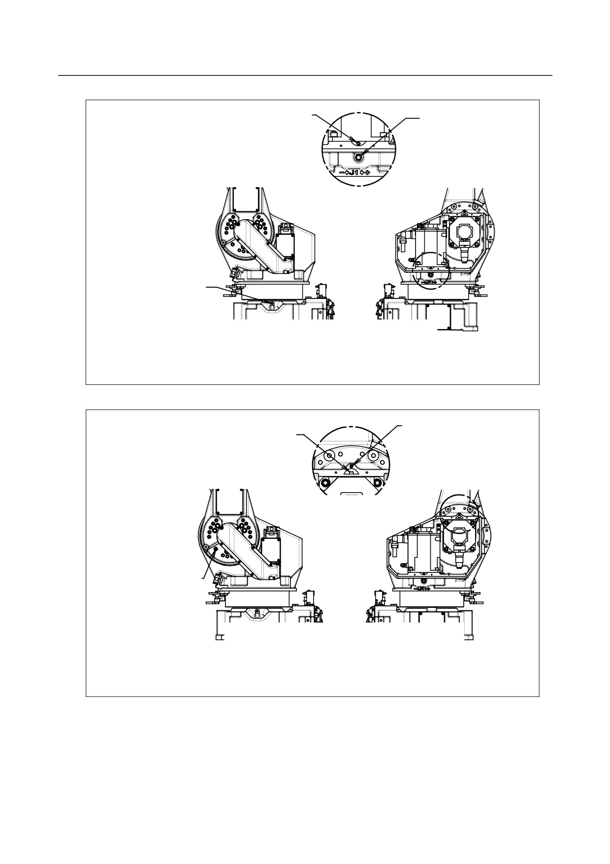
B-82274EN/09
7.CHECKS AND MAINTENANCE
Note)Don't remove
J1-axis reducer
this bolt.
outlet
M12X20(seal bolt)
Detail A
J1-axis reducer inlet
A
Grease nipple
Left side
Right side
Left side
Right side
Fig. 7.2.3 (a) Replacing grease of the J1-axis reducer
J2-axis reducer inlet
Note)Don't remove
Grease nipple
this bolt.
Detail B
B
Detail B
J2-axis reducer
outlet
M12X20(seal bolt)
Left side
Right side
Left side
Right side
Fig. 7.2.3 (b) Replacing grease of the J2-axis reducer
- 85 -
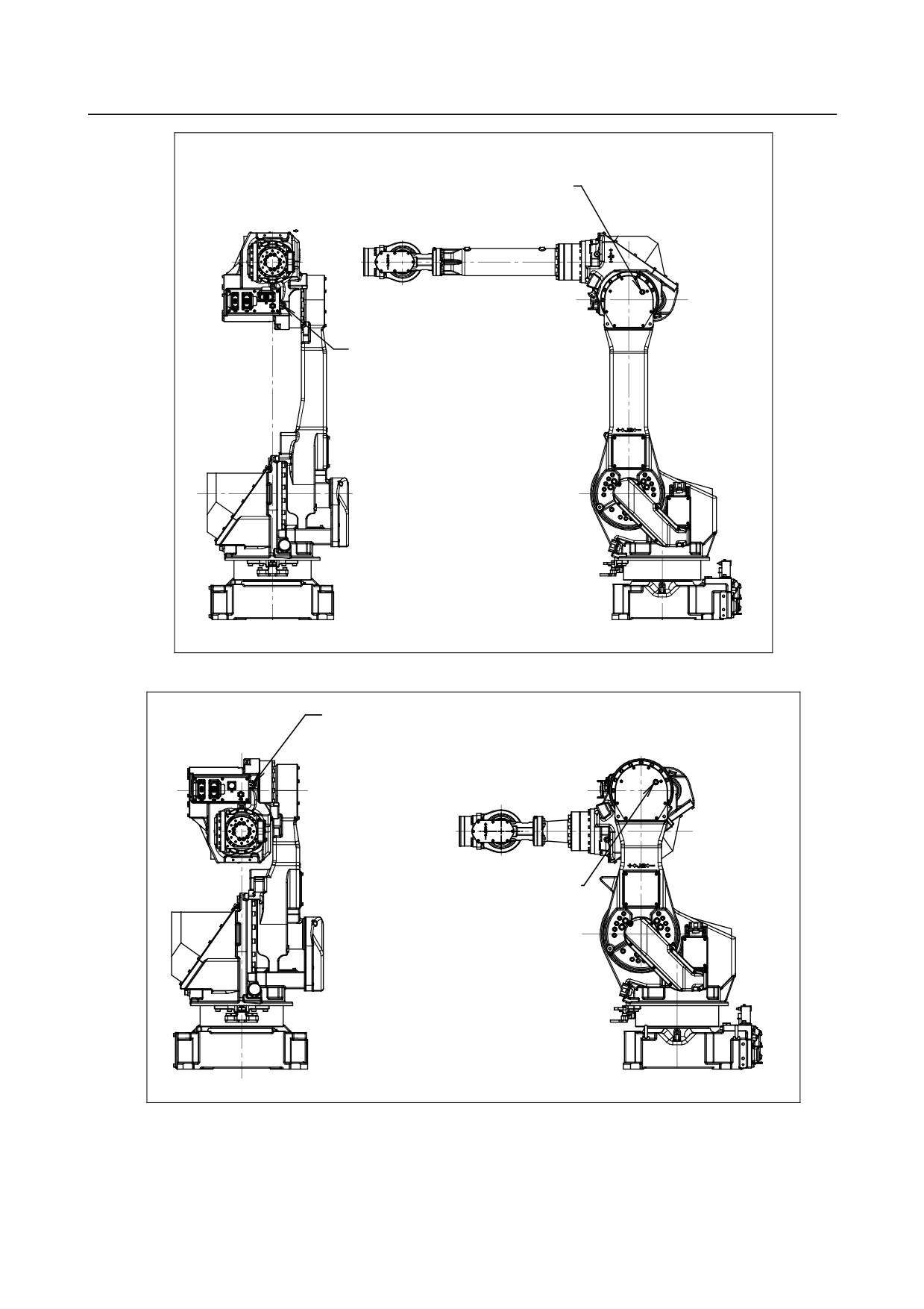
7.CHECKS AND MAINTENANCE
B-82274EN/09
J3-axis reducer
outlet
M12X20(seal bolt)
J3-axis reducer inlet
Grease nipple
Fig. 7.2.3 (c) Replacing grease of the J3-axis reducer(M-710iC/50, /70, /50H, /50E)
J3-axis reducer inlet
Grease nipple
J3-axis reducer
outlet
M12X20(seal bolt)
Fig. 7.2.3 (d) Replacing grease of the J3-axis reducer(M-710iC/50S)
- 86 -
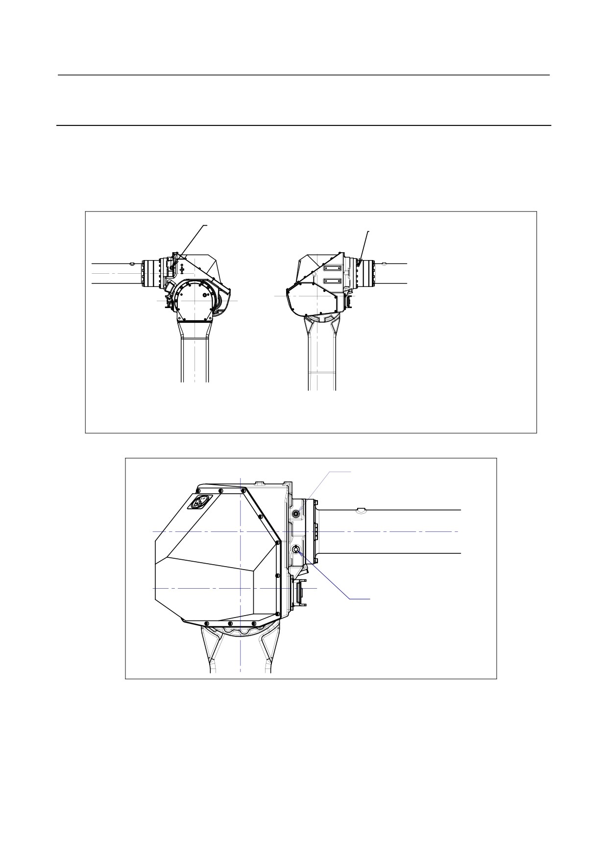
B-82274EN/09
7.CHECKS AND MAINTENANCE
7.2.4
Grease Replacement Procedure for the J4/J5/J6-Axis
Gearbox (J4/J5-axis gearbox)
1
Move the robot to the greasing posture described in Table 7.2.2 (b).
2
Turn off the controller power.
3
Remove the seal bolt from the grease outlet.(Fig. 7.2.4 (a), 7.2.4 (b))
4
Supply new grease until new grease is output from the grease outlet.
5
After greasing, release remaining pressure as the Subsection 7.2.6.
J4/J5/J6-axis gearbox inlet
J4/J5/J6-axis gearbox outlet
Grease nipple
R 1/8(taper plug)
Left side
Right side
Fig. 7.2.4 (a) Replacing grease of the J4/J5/J6-axis gearbox (M-710iC/50, /70, /50E)
J4/J5-axis gearbox outlet
M8X10 (seal bolt)
J4/J5-axis gearbox inlet
Grease nipple
Fig. 7.2.4 (b) Replacing grease of the J4/J5-axis gearbox(M-710iC/50H)
- 87 -
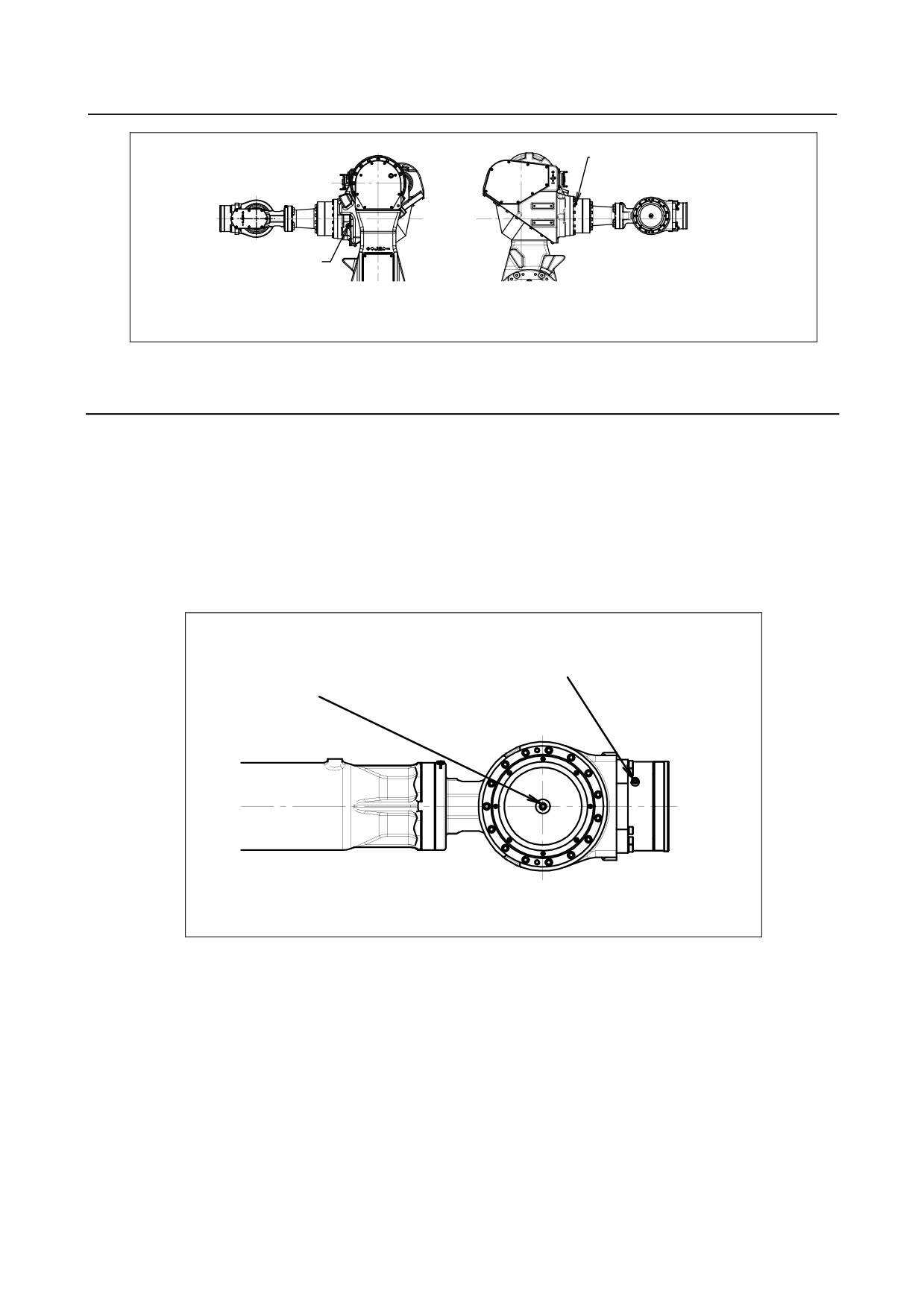
7.CHECKS AND MAINTENANCE
B-82274EN/09
J4/J5/J6-axis gearbox outlet
R 1/8(taper plug)
J4/J5/J6-axis gearbox inlet
Grease nipple
Left side
Right side
Fig. 7.2.4 (c) Replacing grease of the J4/J5/J6-axis gearbox(M-710iC/50S)
7.2.5
Grease Replacement Procedure for the Wrist
Grease Replacement Procedure for the Wrist (M-710iC/50, /70, /50H, /50S)
1
Move the robot to the greasing posture described in Table 7.2.2 (b).
2
Turn off the controller power.
3
Remove the plug with a sealant from the wrist grease outlet and attach the grease nipple that comes
with the robot (Fig. 7.2.5 (a)).
4
Supply new grease through the wrist grease inlet until new grease is output from wrist grease outlet.
5
After greasing, release remaining pressure as the Subsection 7.2.6.
Wrist unit inlet
Wrist unit outlet
(Remove taper plug and attach the
Rc1/8 (taper plug)
grease nipple then supply grease.)
Fig. 7.2.5 (a) Replacing grease of the wrist (M-710iC/50, /70, /50H, /50S)
Grease Replacement Procedure for the Wrist (M-710iC/50E)
1
Move the robot to the greasing posture described in table 7.2.2 (b).
2
Turn off the controller power.
3
Remove the seal bolt of wrist grease outlet 1 (Fig. 7.2.5 (b) ).
4
Supply grease to the wrist grease inlet until new grease outputs from wrist grease outlet 1.
5
Attach the seal bolt to wrist grease outlet 1.
6
Next, remove the seal bolt of wrist grease outlet 2.
7
Supply new grease through the wrist grease inlet until new grease is output from wrist grease outlet
2
8
Release remaining pressure using the procedure given in Section 7.2.6.
- 88 -
B-82274EN/09
7.CHECKS AND MAINTENANCE
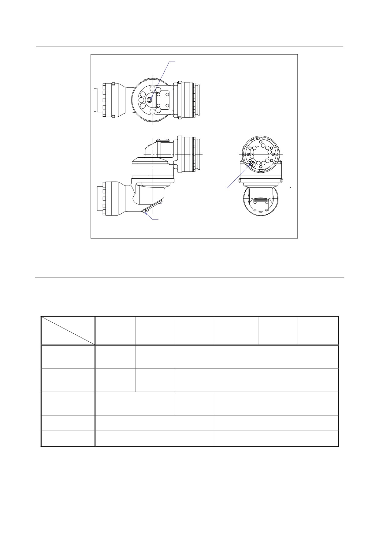
Grease inlet for the
wrist unit
grease nipple
Grease outlet 2 for the
wrist unit
seal bolt M6X8
Grease outlet 1 for the
wrist unit
seal bolt M6X8
Fig. 7.2.5 (b) Replacing grease of the wrist (M-710iC/50E)
7.2.6
Procedure for Releasing Remaining Pressure within the
Grease Bath
After greasing, operate the robot for 20 minutes or more with the grease nipple of the grease inlet and the
seal bolt of the grease outlet uncapped to release remaining pressure within the grease bath.
Attach the reclaim bags under the grease inlet and grease outlet to prevent spilled grease from splattering.
Operating axis
J1-axis
J2-axis
J3-axis
J4-axis
J5-axis
J6-axis
Grease
replacement part
Axis angle of
J1-axis reducer
60° or more
Arbitrary
OVR 80%
Axis angle of
J2-axis reducer
Arbitrary
60° or more
Arbitrary
OVR 100%
Axis angle of
J3-axis reducer
Arbitrary
60° or more
Arbitrary
OVR 100%
Axis angle of 60° or more
J4-axis gearbox
Arbitrary
OVR 100%
Axis angle of 60° or more
Wrist axis
Arbitrary
OVR 100%
If the above operations cannot be performed due to local circumstances, the same count operation is
necessary.
(When the maximum allowable axis angle is 30°, perform twice the operation for 40 minutes
or more.)
When multiple axes are greased at the same time, the axes can be run at the same time.
- 89 -
7.CHECKS AND MAINTENANCE
B-82274EN/09
After the above operation is performed, attach the grease nipple to the grease inlet and the seal bolt to the
grease outlet. When the seal bolt or grease nipple is reused, be sure to seal it with seal tape.
7.3
STORAGE
To store the robot, set it to the same posture as that used for transportation. (See Section 1.1.)
- 90 -
B-82274EN/09
8.MASTERING
8 MASTERING
Mastering is an operation performed to associate the angle of each robot axis with the pulse count value
supplied from the absolute Pulsecoder connected to the corresponding axis motor. To be specific,
mastering is an operation for obtaining the pulse count value corresponding to the zero position.
8.1
GENERAL
The current position of the robot is determined according to the pulse count value supplied from the
Pulsecoder on each axis.
Mastering is factory-performed. It is unnecessary to perform mastering in daily operations. However,
mastering becomes necessary after:
・ Motor replacement.
・ Pulsecoder replacement
・ Reducer replacement
・ Cable replacement
・ Batteries for pulse count backup in the mechanical unit have gone dead
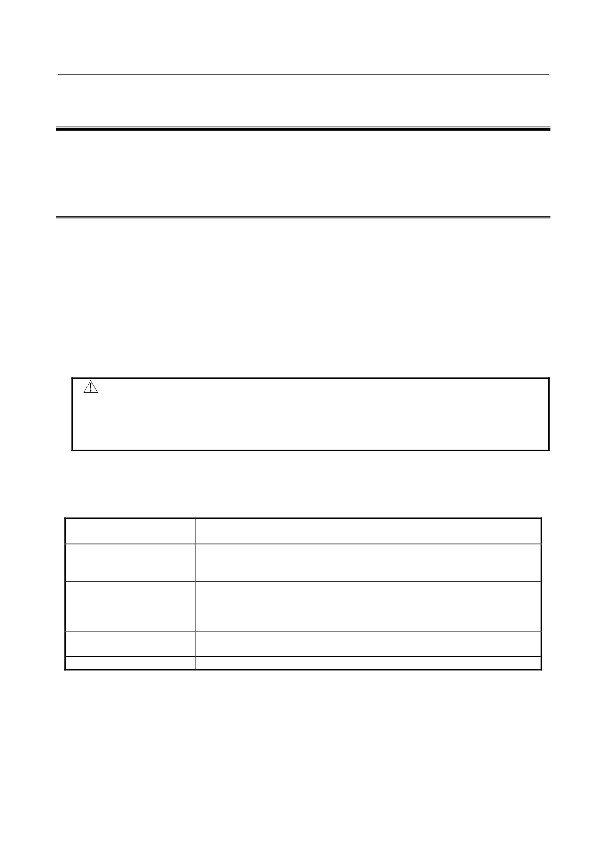
CAUTION
Robot data (including mastering data) and Pulsecoder data are backed up by
their respective backup batteries. Data will be lost if the batteries go dead.
Replace the batteries in the control and mechanical units periodically. An alarm
will be issued to warn the user of a low battery voltage.
Types of Mastering
There are five methods of the following mastering.
Table 8.1 Type of mastering
Fixture position mastering
This is performed using a mastering Fixture before the machine is shipped from
the factory.
Zero-position mastering
This is performed with all axes set at the 0-degree position. A zero-position mark
(witness mark mastering)
(witness mark) is attached to each robot axis. This mastering is performed with all
axes aligned to their respective witness marks.
Quick mastering
This is performed at a user-specified position. The corresponding count value is
obtained from the rotation speed of the Pulsecoder connected to the relevant
motor and the rotation angle within one rotation. Quick mastering uses the fact that
the absolute value of a rotation angle within one rotation will not be lost.
Single-axis mastering
This is performed for one axis at a time. The mastering position for each axis can
be specified by the user. This is useful in performing mastering on a specific axis.
Mastering data entry
Mastering data is entered directly.
Once mastering is performed, it is necessary to carry out positioning, or calibration. Positioning is an
operation in which the controller reads the current pulse count value to sense the current position of the
robot.
This section describes zero-position mastering, quick mastering, single-axis mastering, and mastering data
entry. For more detailed mastering (Fixture position mastering), contact FANUC.
- 91 -
8.MASTERING
B-82274EN/09
CAUTION
If mastering is performed incorrectly, the robot may behave unexpectedly. This is
very dangerous. Therefore, the positioning screen is designed to appear only
when the $MASTER_ENB system variable is 1 or 2. After performing positioning,
press F5 [DONE] on the positioning screen. The $MASTER_ENB system
variable is reset to 0 automatically, thus hiding the positioning screen.
CAUTION
It is recommended that the current mastering data be backed up before
mastering is performed.
8.2
RESETTING ALARMS AND PREPARING FOR
MASTERING
Before performing mastering because a motor is replaced, it is necessary to release the relevant alarm and
display the positioning menu.
Alarm displayed
“Servo 062 BZAL” or “Servo 075 Pulse not established”
Procedure
Step
1
Display the positioning menu by following steps 1 to 6.
1
Press the screen selection key.
2
Press [0 NEXT] and Select [6 SYSTEM].
3
Press F1 [TYPE], and select [SYSTEM Variable] from the menu.
4
Place the cursor on $MASTER_ENB, then key in “1” and press [ENTER].
5
Press F1 [TYPE] again, and select [Master/Cal] from the menu.
6
Select the desired mastering type from the [Master/Cal] menu.
2
To reset the “Servo 062 BZAL” alarm, follow steps 1 to 5.
1
Press the screen selection key.
2
Press [0 NEXT] and select [6 SYSTEM].
3
Press F1 [TYPE], and select [Master/Cal] from the menu.
4
Press the F3 [RES_PCA], then press F4 [TRUE].
5
Turn off the controller power and on again.
3
To reset the “Servo 075 Pulse not established” alarm, follow steps 1 to 3.
1
When the controller power is turned on again, the message “Servo 075 Pulse not established”
appears again.
2
Move the axis for which the message mentioned above has appeared till alarm disappears when
press [FAULT RESET] in either direction.
- 92 -
B-82274EN/09
8.MASTERING
8.3
ZERO POSITION MASTERING
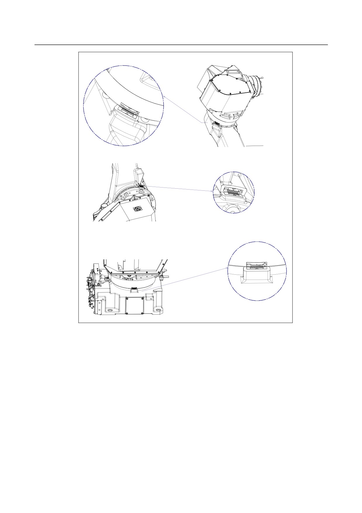
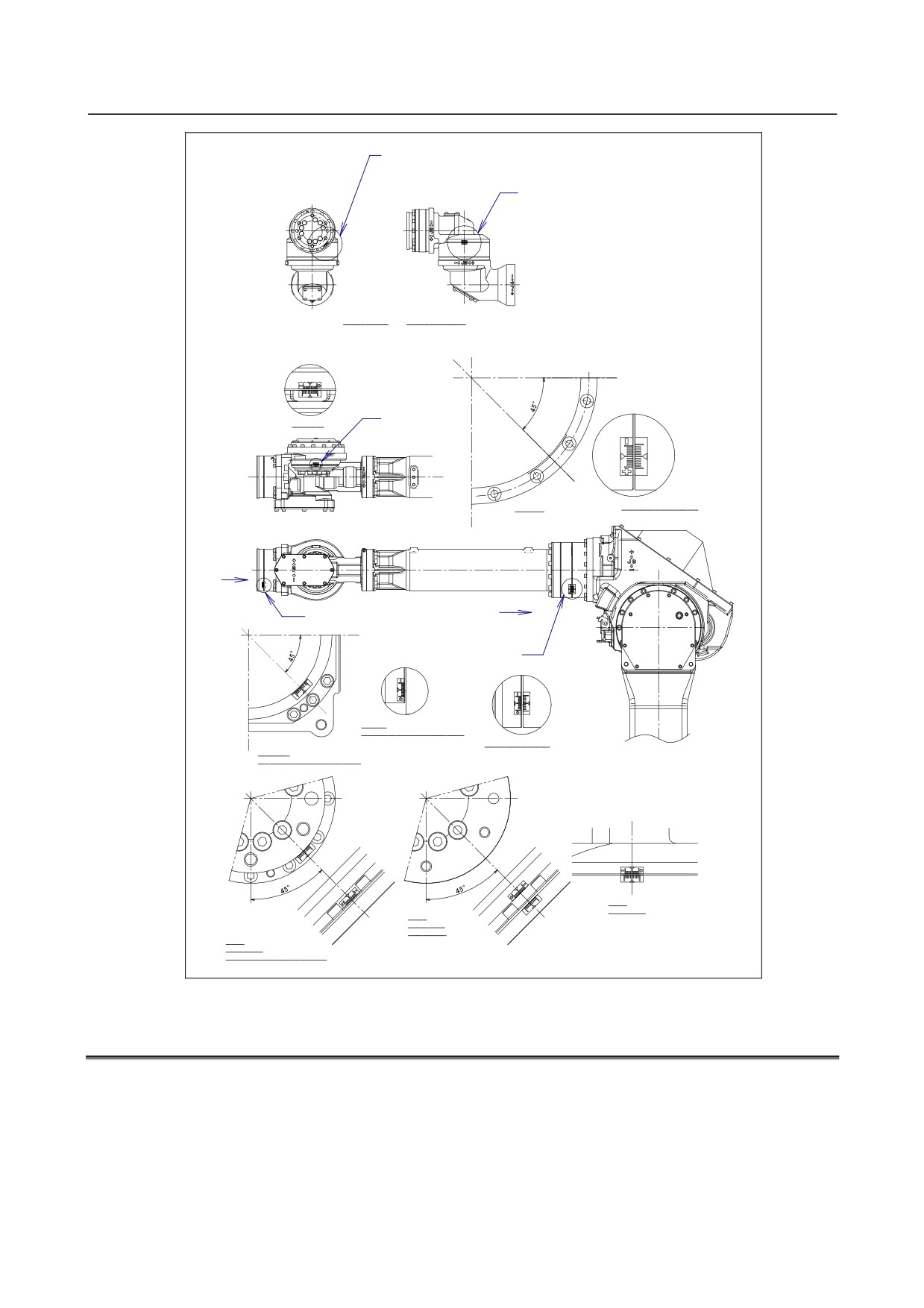
Zero-position mastering (witness mark mastering) is performed with all axes set at the 0-degree position.
A zero-position mark (witness mark) is attached to each robot axis. This mastering is performed with all
axes set at the 0-degree position using their respective witness marks.
Zero-position mastering involves a visual check. It cannot be so accurate. It should be used only as a
quick-fix method.
Procedure of Zero-position Mastering
1.
Press MENUS.
2.
Select NEXT and press SYSTEM.
3.
Press F1, [TYPE].
4.
Select Master/Cal.
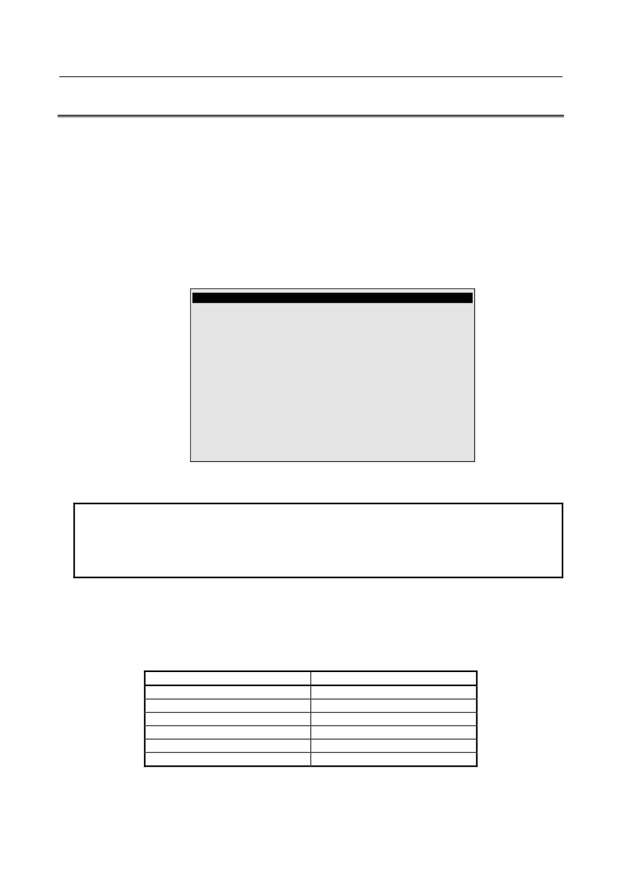
SYSTEM Master/Cal
JOINT 10%
1 FIXTURE POSITION MASTER
2 ZERO POSITION MASTER
3 QUICK MASTER
4 SINGLE AXIS MASTER
5 SET QUICK MASTER REF
6 CALIBRATE
Press 'ENTER' or number key to select.
[ TYPE ] LOAD
RES_PCA
DONE
5.
Release brake control, and jog the robot into a posture for mastering.
NOTE
Brake control can be released by setting the system variables as follows:
$PARAM_GROUP.SV_OFF_ALL: FALSE
$PARAM_GROUP.SV_OFF_ENB[*]: FALSE (for all axes)
After changing the system variables, turn off the controller power and on again.
6.
Select Zero Position Master.
7.
Press F4, YES. Mastering will be performed automatically. Alternatively, turn off the controller
power and on again. Turning on the controller power always causes positioning to be performed.
8.
Return brake control to original setting, and turn off the controller power and on again.
Table 8.3 Posture with position marks (witness mark) aligned
Axis
Position
J1-axis
0 deg
J2-axis
0 deg
J3-axis
0 deg (NOTE) When J2-axis is 0 deg.
J4-axis
0 deg
J5-axis
0 deg
J6-axis
0 deg
- 93 -
8.MASTERING
B-82274EN/09
C
J3
J2
J1
Fig. 8.3 (a) zero-position mark (witness mark) for each axis
- 94 -
B-82274EN/09
8.MASTERING
F (offset wrist)
E (offset wrist)
M-710iC/50E (offset wrist)
DETAIL E
E
VIEW DD
DETAIL D (except 50H)
FF
F
DD
D
Detail F
(FANUC Flange, Special Flange)
Detail F(ISO Flange)
DIetail FF
(FANUC Flange, Special Flange)
Detail
offset wrist
Detail
offset wrist
(ISO flange)
Detail
offset wrist
(FANUC flange, Special Flange)
Fig. 8.3 (b) zero-position mark (witness mark) for each axis
8.4
QUICK MASTERING
Quick mastering is performed at a user-specified position. The corresponding count value is obtained
from the rotation speed of the Pulsecoder connected to the relevant motor and the rotation angle within
one rotation. Quick mastering uses the fact that the absolute value of a rotation angle within one rotation
will not be lost.
Quick mastering is factory-performed at the position indicated in Table 8.3. Do not change the setting
unless there is any problem.
- 95 -
8.MASTERING
B-82274EN/09
If it is impossible to set the robot at the position mentioned above, it is necessary to re-set the quick
mastering reference position using the following method. (It would be convenient to set up a marker that
can work in place of the witness mark.)
CAUTION
1 Quick mastering can be used, if the pulse count value is lost, for example,
because a low voltage has been detected on the backup battery for the pulse
counter.
2 Quick mastering cannot be used, after the Pulsecoder is replaced or after the
mastering data is lost from the robot controller.
Procedure Recording the Quick Mastering Reference Position
1
Select SYSTEM.
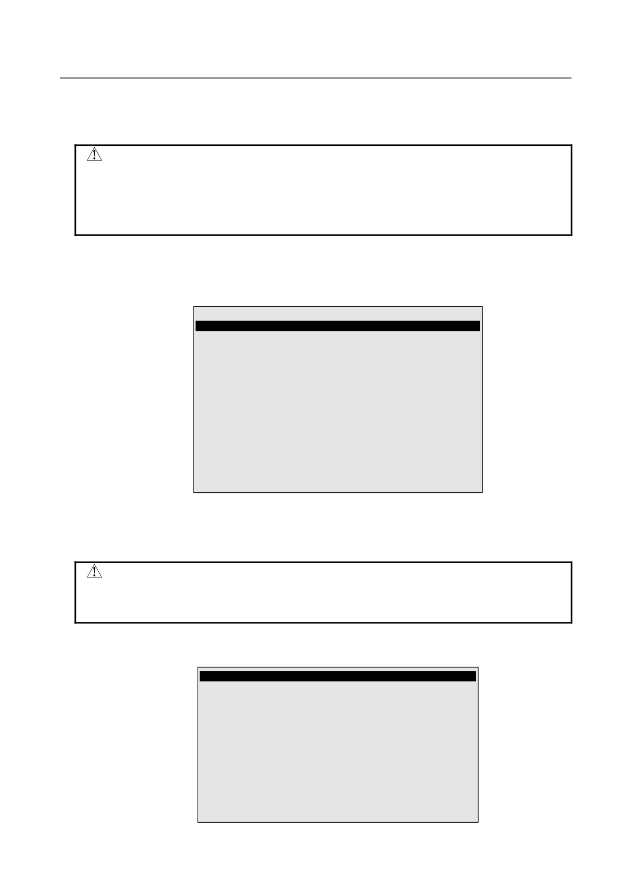
2
Select Master/Cal.
SYSTEM Master/Cal
JOINT 10%
1 FIXTURE POSITION MASTER
2 ZERO POSITION MASTER
3 QUICK MASTER
4 SINGLE AXIS MASTER
5 SET QUICK MASTER REF
6 CALIBRATE
Press 'ENTER' or number key to select.
[ TYPE ] LOAD
RES_PCA
DONE
3
Release brake control, and jog the robot to the quick mastering reference position.
4
Set quick master ref? [NO] Move the cursor to SET QUICK MASTER REF and press ENTER.
Press F4, YES.
CAUTION
If the robot has lost mastery due to mechanical disassembly or repair, you
cannot perform this procedure. In this case, Fixture position mastering or zero
-position mastering to restore robot mastery.
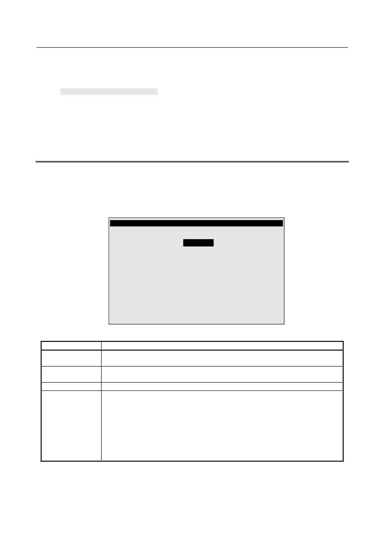
Procedure of Quick Mastering
1
Display the Master/Cal screen.
SYSTEM Master/Cal
JOINT 10%
1 FIXTURE POSITION MASTER
2 ZERO POSITION MASTER
3 QUICK MASTER
4 SINGLE AXIS MASTER
5 SET QUICK MASTER REF
6 CALIBRATE
Press 'ENTER' or number key to select.
[ TYPE ] LOAD
RES_PCA
DONE
- 96 -
B-82274EN/09
8.MASTERING
2
Release brake control, and jog the robot to the quick mastering reference position.
3
Quick master? [NO] Move the cursor to QUICK MASTER and press ENTER. Press F4, YES.
Quick mastering data is memorized.
Quick master? [NO]
4
Move the cursor to CALIBRATE and press ENTER. Calibration is executed. Calibration is
executed by power on again.
5
After completing the calibration, press F5 Done.
6
Return brake control to original setting, and turn off the controller power and on again.
8.5
SINGLE AXIS MASTERING
Single axis mastering is performed for one axis at a time. The mastering position for each axis can be
specified by the user.
Single axis mastering can be used, if mastering data for a specific axis is lost, for example, because a low
voltage has been detected on the pulse counter backup battery or because the Pulsecoder has been
replaced.
SINGLE AXIS MASTER
JOINT 33%
ACTUAL AXIS
(MSTR POS)
(SEL)
[ST]
J1
25.255
(0.000)
(0)
[2]
J2
25.550
(0.000)
(0)
[2]
J3
-50.000
(0.000)
(0)
[2]
J4
12.500
(0.000)
(0)
[2]
J5
31.250
(0.000)
(0)
[2]
J6
43.382
(0.000)
(0)
[2]
E1
0.000
(0.000)
(0)
[2]
E2
0.000
(0.000)
(0)
[2]
E3
0.000
(0.000)
(0)
[2]
GROUP EXE
Table 8.5 Items set in single axis mastering
Item
Description
Current position
The current position of the robot is displayed for each axis in degree units.
(ACTUAL AXIS)
Mastering position
A mastering position is specified for an axis to be subjected to single axis mastering. It
(MSTR POS)
would be convenient to set to it to the 0_ position.
SEL
This item is set to 1 for an axis to be subjected to single axis mastering. Usually, it is 0.
ST
This item indicates whether single axis mastering has been completed for the
corresponding axis. It cannot be changed directly by the user.
The value of the item is reflected in $EACHMST_DON
(1 to 9).
0 :Mastering data has been lost. Single axis mastering is necessary.
1 :Mastering data has been lost. (Mastering has been
performed only for the other interactive axes.) Single axis
mastering is necessary.
2 :Mastering has been completed.
Procedure of Single axis mastering
1
Select SYSTEM.
2
Select Master/Cal.
- 97 -
8.MASTERING
B-82274EN/09
SYSTEM Master/Cal
JOINT 10%
1 FIXTURE POSITION MASTER
2 ZERO POSITION MASTER
3 QUICK MASTER
4 SINGLE AXIS MASTER
5 SET QUICK MASTER REF
6 CALIBRATE
Press 'ENTER' or number key to select.
[ TYPE ] LOAD
RES_PCA
3
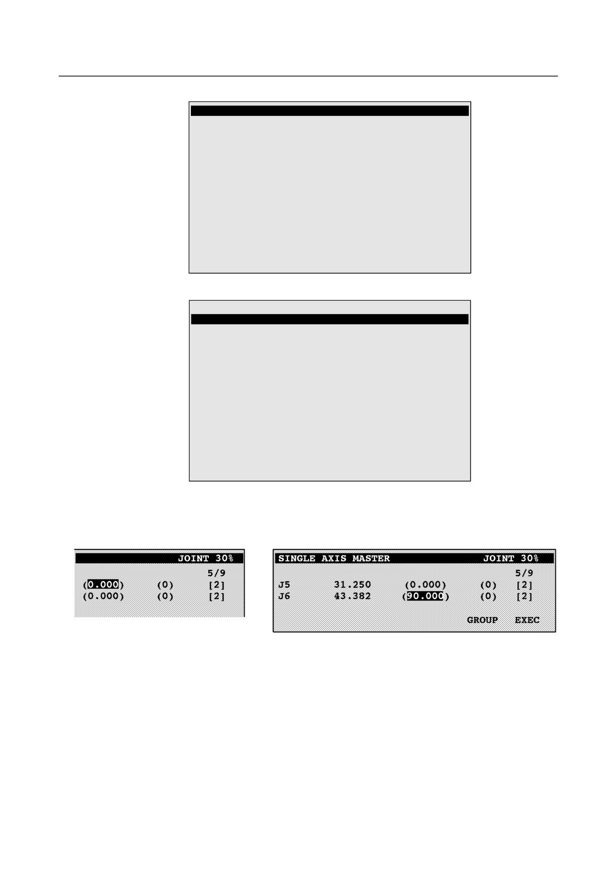
Select 4, Single Axis Master. You will see a screen similar to the following.
SINGLE AXIS MASTER
JOINT 10%
1/9
ACTUAL POS
(MSTR POS)
(SEL)
[ST]
J1
25.255
(
0.000)
(0)
[2]
J2
25.550
(
0.000)
(0)
[2]
J3
-50.000
(
0.000)
(0)
[2]
J4
12.500
(
0.000)
(0)
[2]
J5
31.250
(
0.000)
(0)
[0]
J6
43.382
(
0.000)
(0)
[0]
E1
0.000
(
0.000)
(0)
[2]
E2
0.000
(
0.000)
(0)
[2]
E3
0.000
(
0.000)
(0)
[2]
[ TYPE ]
GROUP EXEC
4.
Move the cursor to the SEL column for the unmastered axis and press the numeric key “1.” Setting
of SEL is available for one or more axes.
5.
Turn off brake control as required, then jog the robot to the mastering position
6.
Enter axis data for the mastering position.
7
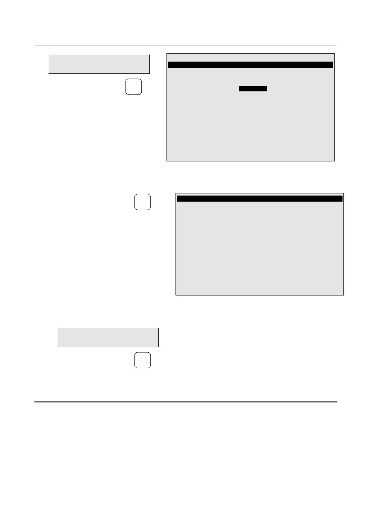
Press F5 [EXEC]. Mastering is performed. Therefore, SEL is reset to 0, and ST is re-set to 2 or 1.
- 98 -
B-82274EN/09
8.MASTERING
SINGLE AXIS MASTER
JOINT 30%
GROUP EXEC
1/9
ACTUAL AXIS
(MSTR POS)
(SEL)
[ST]
F5
J1
25.255
(0.000)
(0)
[2]
J2
25.550
(0.000)
(0)
[2]
J3
-50.000
(0.000)
(0)
[2]
J4
12.500
(0.000)
(0)
[2]
J5
0.000
(0.000)
(0)
[2]
J6
0.000
(0.000)
(0)
[2]
E1
0.000
(0.000)
(0)
[2]
E2
0.000
(0.000)
(0)
[2]
E3
0.000
(0.000)
(0)
[2]
GROUP EXEC
8
When single axis mastering is completed, press the previous page key to resume the previous screen.
SYSTEM Master/Cal
JOINT 30%
BACK
1 FIXTURE POSITION MASTER
2 ZERO POSITION MASTER
3 QUICK MASTER
4 SINGLE AXIS MASTER
5 SET QUICK MASTER REF
6 CALIBRATE
Press 'ENTER' or number key to select.
[ TYPE ]
DONE
9.
Select [6 CALIBRATE], then press F4 [YES]. Positioning is performed. Alternatively, turn off the
controller power and on again. Positioning is performed.
10. After positioning is completed, press F5 [DONE].
DONE
F5
11 Return brake control to original setting, and turn off the controller power and on again.
8.6
MASTERING DATA ENTRY
This function enables mastering data values to be assigned directly to a system variable. It can be used if
mastering data has been lost but the pulse count is preserved.
Mastering data entry method
1
Press MENUS, then press NEXT and select SYSTEM.
2
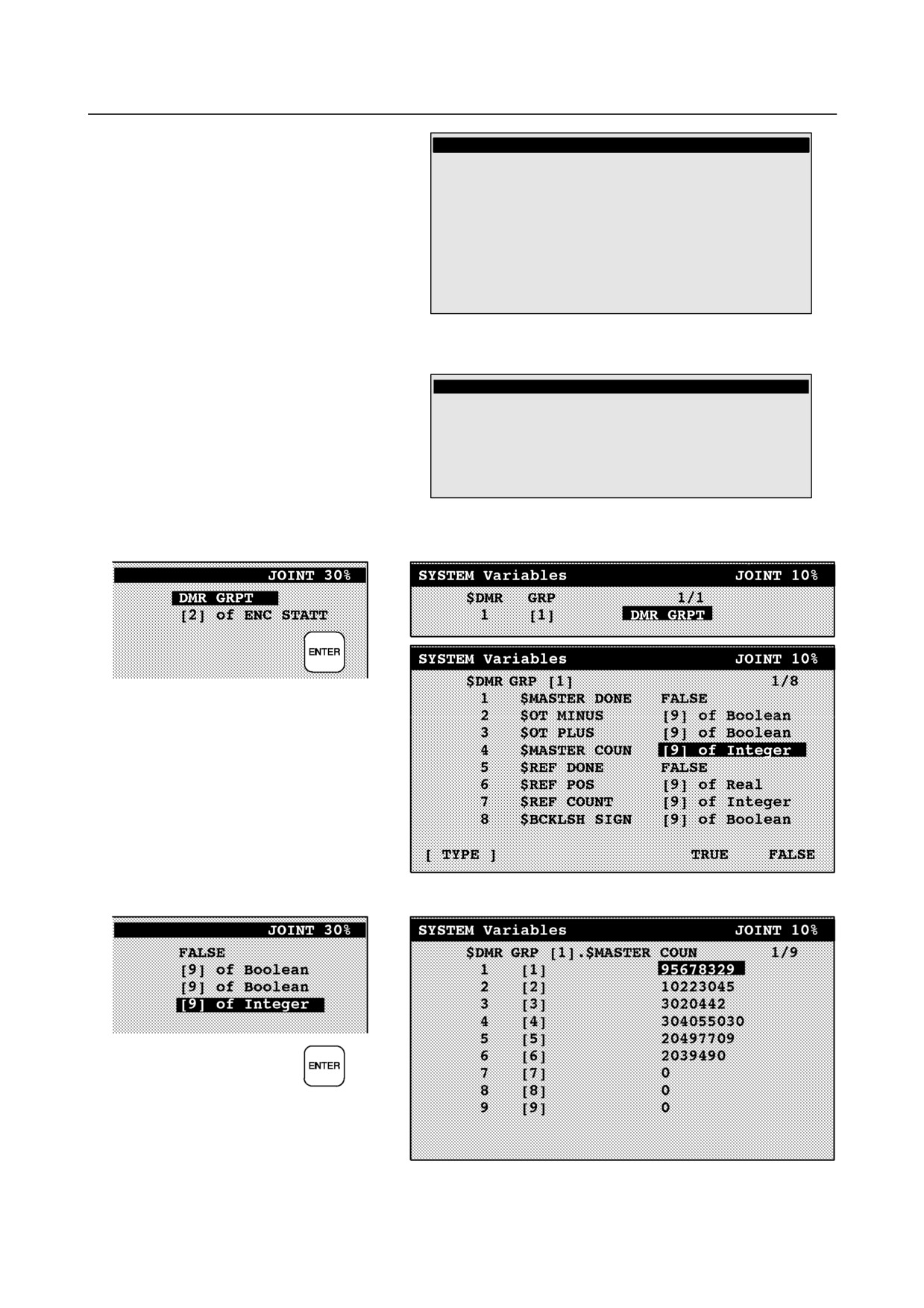
Press F1, [TYPE]. Select [Variables]. The system variable screen appears.
- 99 -
8.MASTERING
B-82274EN/09
SYSTEM Variables
JOINT 10%
1/98
1
$AP MAXAX
536870912
2
$AP PLUGGED
4
3
$AP TOTALAX
16777216
4
$AP USENUM
[12] of Byte
5
$AUTOINIT
2
6
$BLT
19920216
[ TYPE ]
3
Change the mastering data.
The mastering data is saved to the $DMR_GRP.$MASTER_COUN system variable.
SYSTEM Variables
JOINT 10%
13
$DMR GRP
DMR GRPT
14
$ENC STAT
[2] of ENC STATT
[ TYPE ]
4
Select $DMR_GRP.
5
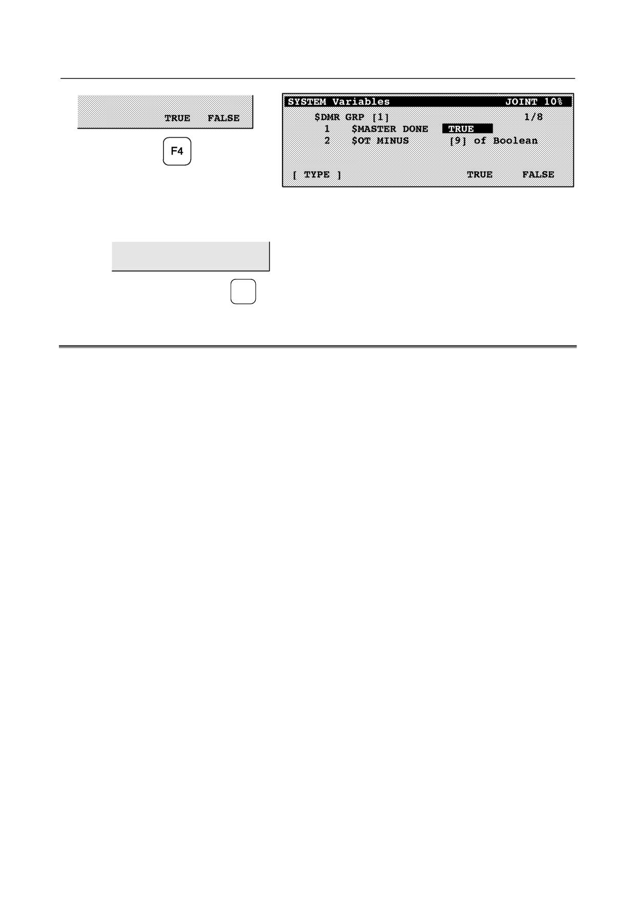
Select $MASTER_COUN, and enter the mastering data you have recorded.
6
Press the PREV key.
7
Set $MASTER_DONE to TRUE.
- 100 -
B-82274EN/09
8.MASTERING
8
Display the positioning screen, and select [6 CALIBRATE], then press F4 [YES].
9
After completing positioning, press F5 [DONE].
DONE
F5
8.7
CHECKING THE MASTERING
1
Checking whether mastering has been made correctly
Usually, positioning is performed automatically at power-on. To check whether mastering has
been made correctly, note whether the displayed current position agrees with the actual robot
position. Use the procedure described below:
(1) Reproduce a particular point in a program. Check whether the point agrees with the specified
position.
(2) Set all axes of the robot to their 0-degree (0rad) positions. Check that the zero-degree position
marks indicated in Section 8.3 are aligned. There is no need to use any visual aid.
(3) Using fixtures, set the robot to the mastering position in the same way as when performing
mastering. Check that the displayed current position agrees with the actual mastering
position.
If the displayed and actual positions do not match, the counter value for a Pulsecoder may have been
invalidated as a result of an alarm described below 2. Alternatively, the mastering data in system
variable $DMR_GRP.$MASTER_COUN may have been overwritten as a result of an operation
error or some other reason.
Compare the data with the values indicated on the supplied data sheet. This system variable is
overwritten whenever mastering is performed. Whenever mastering is performed, record the value
of the system variable on the data sheet.
2
Alarms that may be output during mastering and remedy for it
(1) BZAL alarm
This alarm is output if the voltage of the Pulsecoder's backup battery falls to 0 V while the
power to the controller is disconnected. Also, if Pulsecoder connector is removed for replacing
cables etc. this alarm is output because voltage becomes to 0. To clear the alarm, fit a new
battery, execute the pulse reset (See Section 8.2.), then turn the power off then on again and
confirm alarm is not output.
Battery might be weak if you can’t reset alarm, then replace battery to new one , perform pulse
reset , turn off and on the controller power. Note that, if this alarm occurs, all data originally
held by the Pulsecoder will have been lost. Mastering must be performed again.
- 101 -