FANUC Series 0i-MODEL F Plus. CONNECTION MANUAL (FUNCTION) - page 358
 

  Index      Manuals     FANUC Series 0i-MODEL F Plus. CONNECTION MANUAL (FUNCTION) B-64693EN-1/01


Search            copyright infringement  


Content      ..     356      357      358      359     ..


FANUC Series 0i-MODEL F Plus. CONNECTION MANUAL (FUNCTION) - page 358


19. MAINTENANCE FUNCTION


B-64693EN-1/01


- 2818 - 

19.1.6 

Display the CNC Information 

In the CNC screen, the PMC signal and the signal of the Multi-Sensor Unit can be monitored and the 
CNC information at the time when the trouble of machine occurs is checked. 
The screen for the confirmation has the following two kinds. 

Machine state monitoring screen: Display of current PMC signals and Multi-Sensor Unit 
information. 

Machine state history screen: Display of CNC information at the time when the trouble of machine 
occurs. 


19.1.7 

Machine state monitoring screen 

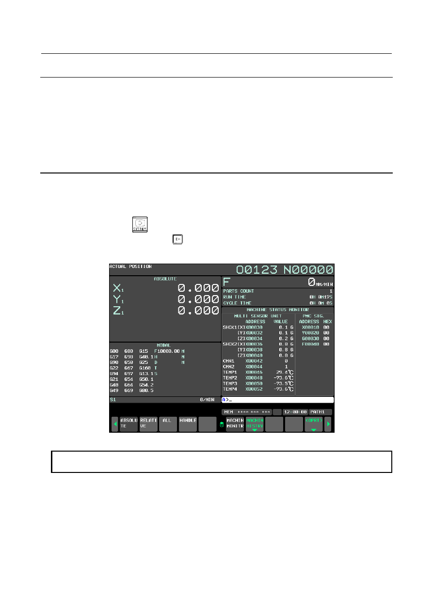
In the machine state  monitoring  screen, four PMC signals that set by parameter and the signal of the 
Multi-Sensor Unit can be monitored. 
 
The machine state monitoring screen is displayed by the following procedures. 

1. 

Press function key 


2. 

Press the continuous menu key 


  several times to display the soft key [MACHIN MONITR] 

3. 

Press the soft key [MACHIN MONITR] to display the machine state monitoring screen. 


Fig. 19.1.7 (a) Machine state monitoring screen(With Multi-Sensor Unit) 


NOTE 


This screen is displayed only when bit 3 (MSM) of parameter No.11372 is 1. 


B-64693EN-1/01


19. MAINTENANCE FUNCTION


- 2819 - 

19.1.7.1 

Monitoring of PMC signals 

In the machine state monitoring screen, four PMC signals that set by parameter can be monitored. 


Fig. 19.1.7.1 (a) Monitoring of PMC signals 

 
Details of the content of the display are as follows. 
 

PMC Signal Title 

The title of PMC signal that can be set by the parameter is displayed. 
The PMC signal can be set only by four bytes or less. 
 

PMC Signal Address 

The address of PMC signal set by the parameter is displayed. 
If the parameter is not set, “****” is displayed. 
In the case of multi PMC system, the PMC path number is displayed ahead of the address. (Refer to Fig. 
19.1.7.1 (b)) 
 

PMC Signal Value 

The real-time value of PMC signal set by the parameter is displayed by Hex. 
If the parameter is not set, “****” is displayed. 


Fig. 19.1.7.1 (b) PMC Signal Value 


Title 

Signal Value 

Signal Address 

Parameter is not set 

PMC path number 

(Multi PMC system) 

19. MAINTENANCE FUNCTION


B-64693EN-1/01


- 2820 - 

19.1.7.2 

With Multi-Sensor Unit 

When Multi-Sensor Unit is connected, machine state monitoring screen is displayed as follows. 


Fig. 19.1.7.2 (a) With Multi-Sensor Unit 

 
Details of the content of the display are as follows. 
 

Multi-Sensor Unit Title 

The title of Multi-Sensor Unit title is displayed. 
 

For the multi PMC system 

In the case of multi PMC system, the PMC path number of the Multi-Sensor Unit is displayed next to the 
title. 


Fig. 19.1.7.2 (b) Multi PMC System 


For the plural Multi-Sensor Units 

The Multi-Sensor Unit can be connected up to four. 
In the case of the plural Multi-Sensor Units, the displayed Multi-Sensor Unit number (MSU No.) and all 
connected number of MSU are displayed. 
The Multi-Sensor Unit number is counted from the one near CNC to four among units connected with I/O 
Link. 


Fig. 19.1.7.2 (c) plural Multi-Sensor Units 


For multi PMC system and the plural Multi-Sensor Units 

In the case of multi PMC system and the plural Multi-Sensor Units, the displayed MSU No, all connected 
number of MSU and the PMC path number of the Multi-Sensor Units are displayed next to the title. 
 

Title 

Sensor Item 

Signal Address 

Value 

Unit 

Title 

Signal Value 

Signal Address 

PMC path number 

MSU No. / All MSU 

B-64693EN-1/01


19. MAINTENANCE FUNCTION


- 2821 - 


Fig. 19.1.7.2 (d) Multi PMC System and plural Multi-Sensor Units 


Sensor Item 

The following sensor items are displayed. 
(1)  Shock Sensor (Direction of X, Y, Z)    : 2CH 
(2)  Analog Input 


: 2CH 

(3)  Thermo Sensor 


: 8CH 

 
When all sensors cannot be displayed in one screen, the page can be switched by pushing page change 

key 


Address 

The address corresponding to each sensor is displayed. 
 

Value 

The sensor value that each sensor outputs is displayed. 
 

Unit 

The unit corresponding to each sensor is displayed. 
 

PMC Signal Title 

Refer to

Monitoring of PMC signals”. 


PMC Signal Address 

Refer to

Monitoring of PMC signals”. 


PMC Signal Value 

Refer to

Monitoring of PMC signals”. 


PMC path number 

MSU No. / All MSU 

19. MAINTENANCE FUNCTION


B-64693EN-1/01


- 2822 - 

Operation 

If the soft key [(OPRT)] is pressed, the following soft keys are displayed. 


Fig. 19.1.7.2 (e) soft key [(OPRT)] 


Soft Key [MSU SWITCH] 

This soft key is displayed when the plural Multi-Sensor Units are connected. 
When this soft key is pressed, the displayed Multi-Sensor Units can be switched. 
For example, when four Multi-Sensor Units are connected, whenever this soft key is pushed, the 
displayed Multi-Sensor Unit changes as MSU No.1 to 2 to 3 to 4 to 1… 
 

Soft Key [SIGNAL SWITCH] 

When this soft key is pressed, either display of X or Y signal can be switched. 


X signal display                                 Y signal display 


[SIGNAL SWITCH] 

B-64693EN-1/01


19. MAINTENANCE FUNCTION


- 2823 - 

Page Change Key 

When the page change key 


  is pressed, the sensor signal information of the next page can be 

displayed. 


Page 1                                       Page 2 


19.1.8 

Machine state history screen 

When the machine state history save request condition is fulfilled, CNC saves the PMC signal, the state of 
CNC and the operation history in CNC as a history. 
In the machine state history screen, these saved histories can be displayed. 
As a result, for example, the machine state  (coordinate, program etc.) and  operation history  at the time 
when a spindle collides can be checked and the investigation of cause of trouble and restoration are easy. 
 
The histories can be saved up to 100. 
 

NOTE 

1  If the machine state history save request condition is fulfilled when the 100 of 

history data have been saved, the new history overwrites the oldest one. 

2  Don’t set the machine state history save request condition fulfilled while the 

machine state history screen is displayed. In this case, CNC Information is 
saved when the display of the screen changes other screen. 

 
The state of CNC saved as a history is as follows. 
 

Table 19.1.8 (a) Saved CNC Information List 

Item 

Remarks 

Time 

Year, Month, Day, Hour, Minute, Second 

PMC Signal 

4bytes 

Machine Position 

All Axis, All Path 

Absolute Position 

All Axis, All Path 

Feedrate 

All Path 

Spindle Speed 

All Axis, All Path 

Program Name (O Number) 

Executing program name, All Path 

Block Number 

Block number of executing program, All Path 

Mode 

All Path 

Modal 

M, S, T, B (Without G code) All Path 

Operation History 

Data of 1/20 of normal operation history. About 400 MDI keys. 
The number of MDI keys decreases when a history with large size such as the 
alarm history is saved. 

Non-Save Number 

Number of information not saved. 


19. MAINTENANCE FUNCTION


B-64693EN-1/01


- 2824 - 

Item 

Remarks 

Multi-Sensor Unit Signals 

Maximum 4 

Save trigger 

SIGNAL :    signal MSUREQ 
ABTRQ :  unexpected abnormal torque is detected 
SV ALM :    servo alarm 
SP ALM :    spindle alarm 

 
The machine state history screen is composed by the following screens: 
(A)  Machine state history list screen 
(B)  Machine state history CNC data screen 
(C)  Machine state history operation history screen 
 
The machine state history list screen is displayed by the following procedures. 

1. 

Press function key 


2. 

Press continuous menu key [+] several times to display the soft key [MACHIN HISTORY] 

3. 

Press the soft key [MACHIN HISTORY]. 

4. 

Press the soft key [LIST], and machine state history list screen is displayed. 

5. 

Press the soft key [CNC DATA], and CNC data screen is displayed. 

6. 

Press the soft key [OPERAT HISTORY] to display the operation history screen is displayed. 


19.1.8.1 

Machine State History List Screen 

The machine state history list screen is composed by the following area. 
(1)  Common area 
(2)  History list area 
(3)  Detail data area 


Fig. 19.1.8.1 (a) Machine State History List Screen 

 
In common area, common information such as the detect time and non-save number of the selection 
history number is displayed. 
In history list area, the detect time of all the histories saved in CNC is displayed in the list. 
In detail data area, the detail data of the selection history number is displayed. 
The following kind of detail data can be displayed. 

(a)  Signal information 
(b)  CNC information 
(c)  Operation history information 

Common 
area 

History 
list area 

Detail 
data 
area 

B-64693EN-1/01


19. MAINTENANCE FUNCTION


- 2825 - 

These kinds can be selected by cursor key 


  or 


Fig. 19.1.8.1 (b) Machine State History List Screen (List + Signal) 


Fig. 19.1.8.1 (c) Machine State History List Screen (List + CNC) 


Fig. 19.1.8.1 (d) Machine State History List Screen (List + Operation History) 


MDI Key 


MDI Key 


Signal 
Information


CNC Information


Operation History 
Information


History List 


MDI Key 


MDI Key 


Content      ..     356      357      358      359     ..