FANUC Series 0i-MODEL F Plus. CONNECTION MANUAL (FUNCTION) - page 280
 

  Index      Manuals     FANUC Series 0i-MODEL F Plus. CONNECTION MANUAL (FUNCTION) B-64693EN-1/01


Search            copyright infringement  


Content      ..     278      279      280      281     ..


FANUC Series 0i-MODEL F Plus. CONNECTION MANUAL (FUNCTION) - page 280


12. PROGRAM COMMAND


B-64693EN-1/01


- 2194 - 


  Example of operation 

An example of operation on a machine of tool rotation type is given below. 
The machine configuration is "BC type reference tool axis Z-axis". 


Fig. 12.16.1.7 (i) Example of operation on a machine of tool rotation type 

 
Sample program 2 
O0200 ; 
N1 G55 ; 
N2 G01 A90.0 F1000 ; 
N3 G68.3 X0 Y0 Z0 R0; 

N4 X10.0 Y0 Z0 ; 
N5 C90.0; 
N6 G68.3 X10.0 Y0 Z0 ; 

N7 G69 ; 


B-64693EN-1/01


12. PROGRAM COMMAND


- 2195 - 


Fig. 12.16.1.7 (j) Machine operation with sample program 2 

 
N3 block: Sets a feature coordinate system according to the tool direction. 
N4 block: Specifies coordinates in the feature coordinate system. 
N5 block: Changes the tool direction. 
N6 block: Sets a feature coordinate system according to the tool direction. 
 

12. PROGRAM COMMAND


B-64693EN-1/01


- 2196 - 

12.16.2 

Multiple Command of Tilted Working Plane Indexing 

12.16.2.1 

Absolute multiple command 

By additionally specifying G68.2 in the tilted working plane indexing mode, a feature coordinate system 
produced by additionally applying coordinate system conversion to the workpiece coordinate system can 
be set. The workpiece coordinate system is resumed by specifying G69. 
This function is enabled by setting bit 0 (MTW) of parameter No. 11221. 
 

Format 

The format of the tilted working plane indexing (G68.2) is applicable. 
Specify the origin of a feature coordinate system in the workpiece coordinate system. 
 

Example of operation 

An example of operation on a tool rotation type machine is explained below. 
The machine configuration is "BC type with the reference tool axis being the Z-axis". 


Fig. 12.16.2.1 (a) Example of operation on a machine of tool rotation type 

 
Sample program 1 
O0100 ; 
N1 G55 ; 
N2 G90 G01 X20.0 Y5.0 Z0 F1000 ; 
N3 G68.2 X20.0 Y5.0 Z0 I0 J90.0 K0 ; 
N4 G53.1 ; 
  : 
N5 X-15.0 Y0 Z-15.0 ; 
N6 G68.2 X5.0 Y20.0 Z0 I90.0 J90.0 K0 ; 
N7 G53.1; 
  : 
N8 G69 ; 
  : 
 

B-64693EN-1/01


12. PROGRAM COMMAND


- 2197 - 


Fig. 12.16.2.1 (b) Machine operation with sample program 1 

 
N4 block: Rotates the tool in the Z-axis direction in the feature coordinate system. 
N5 block: Specifies coordinates in the feature coordinate system. 
N6 block: Sets a new feature coordinate system. 
N7 block: Rotates the tool in the Z-axis direction in the new feature coordinate system. 
 

12. PROGRAM COMMAND


B-64693EN-1/01


- 2198 - 

12.16.2.2 

Incremental multiple command 

By specifying G68.4, coordinate system conversion can be applied to the currently set feature coordinate 
system. 
This function is enabled by setting bit 0 (MTW) of parameter No. 11221. 
 

Format 

The format of the tilted working plane indexing (G68.2) is applicable. 
Specify the origin of a feature coordinate system in the immediately preceding feature coordinate system. 
 

Table 12.16.2.2 (a) Incremental multiple command format 

Specification method 

Incremental multiple command 

Eulerian angle 

G68.4 

Roll-pitch-yaw 

G68.4 P1 

Three points 

G68.4 P2 

Two vectors 

G68.4 P3 

Projection angles 

G68.4 P4 


Example of operation 

An example of operation on a tool rotation type machine is explained below. 
Rotary axis C rotates about the Z-axis (master axis). 
Rotary axis B rotates about the Y-axis (slave axis). 


Fig. 12.16.2.2 (a) Example of operation on a machine of tool rotation type 

 
Sample program 2 
O0200 ; 
N1 G55 ; 
N2 G90 G01 X20.0 Y5.0 Z0 F1000 ; 
N3 G68.2 X20.0 Y5.0 Z0 I0 J90.0 K0 ; 
N4 G53.1 ; 
  : 
N5 X-15.0 Y0 Z-15.0 ; 
N6 G68.4 X-15.0 Y0 Z-15.0 I90.0 J90.0 K-90.0 ; 
N7 G53.1; 
  : 
N8 G69 ; 
  : 

B-64693EN-1/01


12. PROGRAM COMMAND


- 2199 - 


Fig. 12.16.2.2 (b) Machine operation with sample program 2 

 
N4 block: Rotates the tool in the Z-axis direction in the feature coordinate system. 
N5 block: Specifies coordinates in the feature coordinate system. 
N6 block: Applies coordinate system conversion to the feature coordinate system based on Eulerian angle   


to set a new feature coordinate system. 

N7 block: Rotates the tool in the Z-axis direction in the new feature coordinate system. 
 

12. PROGRAM COMMAND


B-64693EN-1/01


- 2200 - 

12.16.3 

Tool Axis Direction Control 

12.16.3.1 

Tool axis direction control 

G53.1 automatically specifies the +Z direction of the feature coordinate system as the tool axis direction. 
 

Example of operation 

The following gives an operation example in the machine configuration below. 

Table rotation type 

Master axis: About the Y-axis (B axis) 

Slave axis: About the Z-axis (C axis) 

Reference tool axis direction: Z direction 

Increment system for the rotation axis: 1/10(IS-C) 

 
Program example 1 
 

G68.2 I90.0 J0.0005 K-90.0 (rotation by 0.0005 degree about the Y-axis) 


G53.1 


The rotation axis position after the G53.1 command is as follows: 


Bit 2 (TFR) of parameter No. 11630 is set to 0 (minimum command unit of the rotation angles: 
0.001 degree): 
B axis: 0.0010 degree 
C axis: 0.0000 degree 


Bit 2 (TFR) of parameter No. 11630 is set to 1 (minimum command unit of the rotation angles: 
0.00001 degree): 
B axis: 0.0005 degree 
C axis: 0.0000 degree 
 

Program example 2 
 

G68.2 I90.0 J10 K-90.0 (rotation by (minimum command unit of the rotation angles 

×

 10) about the 

Y-axis) 


G53.1 


The rotation axis position after the G53.1 command is as follows: 


Bit 2 (TFR) of parameter No. 11630 is set to 0 (minimum command unit of the rotation angles: 
0.001 degree): 
B axis: 0.0100 degree 
C axis: 0.0000 degree 


Bit 2 (TFR) of parameter No. 11630 is set to 1 (minimum command unit of the rotation angles: 
0.00001 degree): 
B axis: 0.0001 degree 
C axis: 0.0000 degree 


About parameters 

(1)  Machine configuration 

When parameters are set, it is important to determine the target machine configuration for parameter 
setting. 
The following explains the machine configuration. 
 

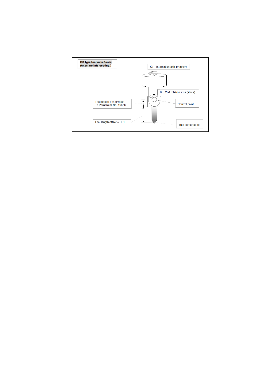
  - 

Master and slave 

When there are two rotation axes for controlling the orientation of a tool or two rotation axes for 
controlling the orientation of a table, a typical structure is such that a rotation mechanism is on the tip of 
another rotation mechanism. The former rotation mechanism is called the slave, and the latter is called the 
master. 
The master and slave are sometimes called the first axis and second axis, respectively. 

B-64693EN-1/01


12. PROGRAM COMMAND


- 2201 - 

The rotation center axis for the master is called the first rotation axis, while the rotation center axis for the 
slave is called the second rotation axis. (Fig. 12.16.3.1 (a)) 


Fig. 12.16.3.1 (a) Relationships between the master and slave 


  - 

When the rotation axes of the table do not intersect 

Explained below is a mechanism in which the table rotation centers do not intersect. 
In the mechanism shown in the following example, the master and slave do not intersect each other. (Fig. 
12.16.3.1 (b)) 
When both the master and slave are at 0 degrees, a vector from the origin of the machine coordinate 
system to a point on the first rotation axis of the table is set as a rotary table position in parameters Nos. 
19700 to 19702. 
Similarly, when both the master and slave are at 0 degrees, a vector from the above point to a point on the 
second rotation axis is set as an intersection offset vector between the first and second rotation axes of the 
table in parameters Nos. 19703 to 19705. 


Fig. 12.16.3.1 (b) Mechanism in which the master and slave do not intersect 


  - 

When the first rotation axis of the tool and the tool axis do not intersect 

Explained below is a mechanism in which the tool axis (spindle rotation center axis) and the first rotation 
axis of the tool do not intersect. 
When both the master and slave are at 0 degrees, a vector from a point at a distance of the tool length 
compensation value plus the tool holder offset value from the tool center point along the tool  axis to a 
point on the first rotation axis of the tool is set as an intersection offset vector between the tool axis and 
the first rotation axis of the tool in parameters Nos. 19709 to 19711. 


Content      ..     278      279      280      281     ..