FANUC Series 0i-MODEL F Plus. CONNECTION MANUAL (FUNCTION) - page 277
 

  Index      Manuals     FANUC Series 0i-MODEL F Plus. CONNECTION MANUAL (FUNCTION) B-64693EN-1/01


Search            copyright infringement  


Content      ..     275      276      277      278     ..


FANUC Series 0i-MODEL F Plus. CONNECTION MANUAL (FUNCTION) - page 277


12. PROGRAM COMMAND


B-64693EN-1/01


- 2170 - 

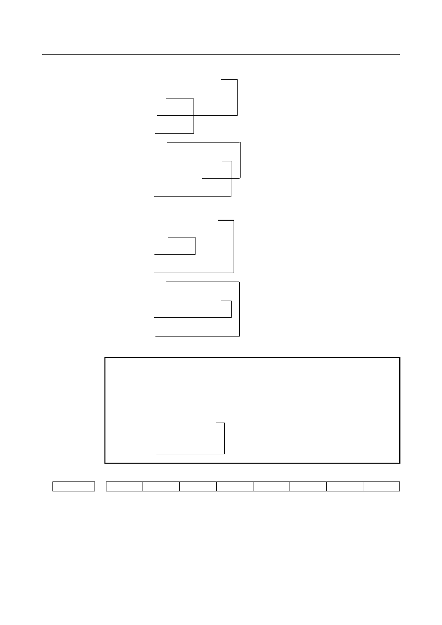
Example 1) An alarm is raised in the following cases:

1

) G68 X_ Y_ Z_ I_ J_ K_ R_ ;

    :
   G43 H1 ;
    :
   G69 ;
    :
   G49 ;
2) G43 H1 ;
    :
      G68 X_ Y_ Z_ I_ J_ K_ R_ ;
    :
   G49(G43H2,H2 etc.) ;
    :
   G69 ;

 PS0049 raised

 PS0049 raised


Example 2) No alarm is raised in the following cases:
3) G68 X_ Y_ Z_ I_ J_ K_ R_ ;
    :
   G43 H1 ;
    :
   G49 ;
    :
   G69 ;
4) G43 H1 ;
    :
      G68 X_ Y_ Z_ I_ J_ K_ R_ ;
    :
   G69 ;
    :
   G49 ;


NOTE 


A command to cancel tool length compensation (G28, etc.) will not 
cause an alarm to be raised. If such a command is specified in the 
G68 mode, program as indicated in 3) above. 

  G43 H1 ;
  :
  G68 X_ Y_ Z_ I_ J_ K_ R_ ;
  :
  G28 X_ Y_ Z_ ;                  

 Offset is cancelled.

  :                                 No alarm is raised.
  G69 ;


#7 

#6 

#5 

#4 

#3 

#2 

#1 

#0 

5400 


LV3 


D3R 


[Input type]  Parameter input 


[Data type]  Bit path 


#2  D3R

  When Reset is done by reset operation or reset signal from PMC, 3-dimensional 

coordinate system conversion mode and tilted working plane indexing mode is: 
0: 

Canceled. 

1: 

Not canceled. 


B-64693EN-1/01


12. PROGRAM COMMAND


- 2171 - 


#5  LV3

  When system variables #100101 to #100132 (current position coordinates) and #100151 

to #100182 (skip coordinates) are read in the 3-dimensional coordinate conversion mode 
or tilted working plane indexing mode: 
0: 

Coordinates of the workpiece coordinate system can be read. 

1: 

Coordinates of the program coordinate system after 3-dimensional coordinate 
conversion or tilted working plane indexing can be read. 

This parameter applies also to system variables #5041 to #5060 (current position 
coordinates) and #5061 to #5080 (skip coordinates). 
 

5412 


Rapid traverse rate for canned cycle for drilling in 3-dimensional coordinate conversion mode 


[Input type]  Parameter input 


[Data type]  Real path 


[Unit of data]  mm/min, inch/min, deg/min (machine unit) 

[Min. unit of data]  Depend on the increment system of the reference axis 
[Valid data range]  Refer to the standard parameter setting table (C) 

(When the increment system is IS-B, 0.0 to +999000.0) 
This parameter sets a rapid traverse rate for canned cycle for drilling in the 3-dimensional 
coordinate conversion mode or the tilted working plane indexing mode. 


#7 

#6 

#5 

#4 

#3 

#2 

#1 

#0 

7301 


3DD 


[Input type]  Parameter input 


[Data type]  Bit path 


#1  3DD

  In program restart operation, when the restart block is in 3-dimensional coordinate 

conversion mode G68 (machining center system) or G68.1 (lathe system), the tool moves 
to the restart point along each axis: 
0: 

According to the program coordinate system in dry run. 

1: 

According to the workpiece coordinate system in dry run. 

The restart coordinates and restart travel distance are also displayed in the coordinate 
system set in this parameter. 
 

NOTE 


The change made to this parameter during program restart 
operation is ignored. 


#7 

#6 

#5 

#4 

#3 

#2 

#1 

#0 

11216 


D3O 


[Input type]  Parameter input 


[Data type]  Bit path 


#0  D3O

  When the bit  1  (D3M) of parameter No.11600 set to “1”  and  Override  is 0%, during 

Tilted working plane indexing or 3-dimensional coordinate system conversion mode, the 
axis moving signals “MV1 to MV8<Fn102>” : 
- 3-dimensional coordinate system conversion 
- Tilted working plane indexing 
0: 

becomes 0. 

1: 

maintains the state of “1”. 


12. PROGRAM COMMAND


B-64693EN-1/01


- 2172 - 

NOTE 


When the manual operation (Jog feed / Incremental feed / Manual 
handle interrupt)is being executed, the bit 0 (D3O) of parameter 
No.11216 become invalid. It becomes operation corresponding to 
D3O=0. 


#7 

#6 

#5 

#4 

#3 

#2 

#1 

#0 

11221 


3CS 


TLC 

3DW 

D3R 


[Input type]  Parameter input 


[Data type]  Bit path 


#1  D3R

  In the 3-dimensional coordinate system conversion mode or tilted working plane indexing 

mode, rapid traverse in canned cycle for drilling is: 
0: 

Performed in the cutting feed mode. 

1: 

Performed in the rapid traverse mode. 


#2  3DW

  If, in the 3-dimensional coordinate system conversion mode, workpiece coordinate 

system selection using a G code is specified, the selection: 
0: 

Operates in accordance with conventional specifications. (The workpiece coordinate 
system difference is reflected in the program coordinate system direction.) 

1: 

Operates in accordance with the same specifications as those of workpiece 
coordinate system selection (bit 6 (3TW) of parameter No. 1205 = 1) during the 
tilted working  plane indexing command. (The workpiece coordinate system 
difference is reflected in the workpiece coordinate system direction.) 


  CAUTION 


If this parameter is set to 1, only G54 to G59 and G54.1 can be 
specified. If G52 and G92 are specified, alarm PS5462, "ILLEGAL 
COMMAND (G68.2/G69)" is issued. 
If G54 to G59 and G54.1 are specified, buffering is suppressed. 


#3  TLC

  During tool length compensation, 3-dimensional coordinate conversion: 

0: 

Cannot be used. 

1: 

Can be used. 


#6  3CS

  The spindle speed calculation of constant surface speed control during the 3-dimensional 

coordinate system conversion / the tilted working plane indexing is : 
0: 

Based on the workpiece coordinate system. 

1: 

Based on the program coordinate system  (3-dimensional coordinate system 
conversion) / the feature coordinate system (Tilted working plane indexing). 


#7 

#6 

#5 

#4 

#3 

#2 

#1 

#0 

11223 


ITM 


[Input type]  Parameter input 


[Data type]  Bit path 


#5  ITM

  When bit 2 (D3IT) of parameter No.11600 =  1, during 3-dimensional coordinate 

conversion, the following signals are: 
0: 

Enabled for axis of programming coordinate system. 

1: 

Enabled for axis of machine coordinate system. 

(Intended signals) 

B-64693EN-1/01


12. PROGRAM COMMAND


- 2173 - 

-  Interlock signal for each axis direction during manual intervention / manual handle 

interrupt in 3-dimensional coordinate system conversion mode 

-  Interlock signal for each axis during manual intervention / manual handle interrupt in 

3-dimensional coordinate system conversion mode 

-  External deceleration signal during manual intervention / manual handle interrupt in 

3-dimensional coordinate system conversion mode 

- External deceleration signal during 3-dimensional coordinate conversion 


#7 

#6 

#5 

#4 

#3 

#2 

#1 

#0 

11600 


D3A 


D3IT 

D3MV 


[Input type]  Parameter input 


[Data type]  Bit path 


#1  D3MV

  In following modes, axis moving signals MV1 to MV8 <Fn102> is: 

- 3-dimensional coordinate system conversion 
- Tilted working plane indexing 
0: 

The signals for axes on programming coordinate system. 

1: 

The signals for axes on workpiece coordinate system. 


#2  D3IT

  In the 3-dimensional coordinate system conversion mode, the valid interlock signals 

(interlock signal for each axis (*ITx) or interlock signal for each axis direction (MITx, 
PITx)) are: 
0: 

The signals for all of the target axes for 3-dimensional coordinate system 
conversion. 

1: 

The signals for axes along which a movement is made during 3-dimensional 
coordinate system conversion. 

 
(Example) 
In case of this parameter is set to 0: 

When interlock signal for each axis (X-axis) is enabled, all axes for 3-dimensional 
coordinate system conversion are interlocked. 
When interlock signal for each axis direction (+X-axis) is enabled, the axis is 
interlocked in +X direction of programming coordinate system of 3-dimensional 
coordinate system conversion. 

In case of this parameter is set to 1: 

When interlock signal for each axis (X-axis) is enabled, the X axis is interlocked in 
machine coordinate system. 


#4  D3A

  In  3-dimensional coordinate system conversion  cancellation, if the compensation vector 

has not been canceled: 
0: 

Alarm PS5462, "ILLEGAL COMMAND (G68.2/G69)", is issued. 

1: 

No alarm is issued. 


#7 

#6 

#5 

#4 

#3 

#2 

#1 

#0 

11630 


FRD 


[Input type]  Parameter input 


[Data type]  Bit path 


#0  FRD

  The minimum command unit of the rotation angles of coordinate rotation and 

3-dimensional coordinate system conversion is: 
0: 

0.001 degree. 

1: 

0.00001 degree. (1/100,000) 


12. PROGRAM COMMAND


B-64693EN-1/01


- 2174 - 


#7 

#6 

#5 

#4 

#3 

#2 

#1 

#0 

19602 


D3D 


[Input type]  Parameter input 


[Data type]  Bit path 


#5  D3D

  Specifies whether to display the distance to go in the program coordinate system or 

workpiece coordinate system during the 3-dimensional coordinate system conversion or 
the tilted working plane indexing. 
0: 

Display the distance to go in the program coordinate system. 

1: 

Display the distance to go in the workpiece coordinate system. 


Alarm and message 

Number 

Message 

Description 

PS0047 

ILLEGAL AXIS SELECT 

Two or more parallel axes (in parallel with a basic axis) have been 
specified upon start-up of 3-dimensional coordinate conversion. 

PS0048 

BASIC 3 AXIS NOT FOUND  Start-up of 3-dimensional coordinate conversion has been attempted, 

but the three basic axes used when Xp, Yp, or Zp is omitted are not set 
in parameter No. 1022. 

PS5043 

TOO MANY G68 NESTING 

3-dimensional coordinate conversion has been specified three or more 
times. 
To perform another coordinate conversion, perform cancellation, then 
specify the coordinate conversion. 

PS5044 

G68 FORMAT ERROR 

Errors for 3-dimensional coordinate conversion command are: 
(1) No I, J, or K command was issued in 3-dimensional coordinate 

conversion command block. 

(2) All of I, J, or K command were 0 in 3-dimensional coordinate 

conversion command block. 

(3) No rotation angle R was commanded in 3-dimensional coordinate 

conversion command block. 

PS5131 

NC COMMAND IS NOT 
COMPATIBLE 

The PMC axis control and 3-dimensional coordinate conversion or polar 
coordinate interpolation were specified simultaneously. Modify the 
program or ladder. 

PS5324 

REFERENCE RETURN 
INCOMPLETE 

No manual reference position return can be made during 3-dimensional 
coordinate conversion or tilted working plane indexing execution. 


Reference item 

Manual name 

Item name 

OPERATOR’S MANUAL (B-64694EN) 

3-dimensional coordinate conversion 


B-64693EN-1/01


12. PROGRAM COMMAND


- 2175 - 

12.16 

TILTED WORKING PLANE INDEXING 

12.16.1 

Tilted Working Plane Indexing 

Overview 

Programming for creating holes, pockets, and other figures in a datum plane tilted with respect to the 
workpiece would be easy if commands can be specified in a coordinate system fixed to this plane (called 
a feature coordinate system). This function enables commands to be specified in the feature coordinate 
system. The feature coordinate system is defined in the workpiece coordinate system. 
For explanations about the relationship between the feature coordinate system and workpiece coordinate 
system, see Fig. 12.16.1 (a). 


Fig. 12.16.1 (a) Feature coordinate system 

 
The G68.2 command causes the programming coordinate system to switch to the feature coordinate 
system. The commands in all subsequent blocks are assumed to be specified in the feature coordinate 
system until G69 appears. 
If G68.2 specifies the relationship between the feature coordinate system and the workpiece coordinate 
system, G53.1 automatically specifies the +Z direction of the feature coordinate system as the tool axis 
direction even if no angle is specified for the rotation axis. (See Fig. 12.16.1 (c).) 
For explanations about the tool axis direction, see Fig. 12.16.1 (b). 


Fig. 12.16.1 (b) Tool axis direction 

 
This function regards the direction normal to the machining plane as the +Z-axis direction of the feature 
coordinate system. After the G53.1 command, the tool is controlled so that it remains perpendicular to the 
machining plane. 

12. PROGRAM COMMAND


B-64693EN-1/01


- 2176 - 


Fig. 12.16.1 (c) G68.2 and G53.1 commands 

 
This function is applicable to the following machine configurations. (See Fig. 12.16.1 (d).) 
<1>  Tool rotation type machine controlled with two tool rotation axes 
<2>  Table rotation type machine controlled with two table rotation axes 
<3>  Composite type machine controlled with one tool rotation axis and one table rotation axis 
 
The function can also be used for a machine configuration in which the rotation axis for controlling the 
tool does not intersect the rotation axis for controlling the table. 

Coordinate system 

origin shift


Xc 

Yc 

Zc 

Workpiece 

coordinate system 

X-Y-Z 

Feature coordinate 

system 

Xc-Yc-Zc


  Only G68.2 is specified 

  G53.1 is specified after G68.2 

Xc 

Yc 

Zc 

Control point shift (by 

another command)


G53.1 automatically controls 

the rotation axis.


Feature coordinate 

system 

Xc-Yc-Zc


Coordinate system 

origin shift


Workpiece 

coordinate system 

X-Y-Z 


B-64693EN-1/01


12. PROGRAM COMMAND


- 2177 - 


<2>  Table rotation type 

machine


<3>  Composite type machine


<1>  Tool rotation 

type machine 


X


C


B


Z


Y


A


C


X


Z


Y


B


Y


X


Z


Fig. 12.16.1 (d) Three types of 5-axis machine 


12.16.1.1 

Tilted working plane indexing based on Eulerian angle 

Coordinate conversion using an Euler's angle 

Coordinate conversion by rotation is assumed to be performed around the workpiece coordinate system 
origin. 
Let the coordinate system obtained by rotating the workpiece coordinate system around the Z-axis by an 
angle of 

α

  degrees be coordinate system 1. Similarly, let the coordinate system obtained by rotating 

coordinate system 1 around the X’-axis by an angle of 

β

 be coordinate system 2. The feature coordinate 

system is the coordinate system obtained by shifting the coordinate system that is obtained by rotating 
coordinate system 2 around the Z”-axis through an angle of 

γ

  degrees from the workpiece coordinate 

system origin by (Xo, Yo, Zo). 
Fig.    shows the relationship between the workpiece coordinate system and the feature coordinate system. 
The figure also gives examples of displacement on the X-Y plane. 


Content      ..     275      276      277      278     ..