FANUC Series 0i-MODEL F Plus. CONNECTION MANUAL (FUNCTION) - page 237
 

  Index      Manuals     FANUC Series 0i-MODEL F Plus. CONNECTION MANUAL (FUNCTION) B-64693EN-1/01


Search            copyright infringement  


Content      ..     235      236      237      238     ..


FANUC Series 0i-MODEL F Plus. CONNECTION MANUAL (FUNCTION) - page 237


10. SPINDLE SPEED FUNCTION


B-64693EN-1/01


- 1850 - 


Servo motor rotation 

Servo motor spindle control mode   

acc./dec. completion signal SVAR (output) 

servo motor spindle control mode signal 

SVSPM (output) 

Servo motor spindle switching signal 

SVSP (input) 

Servo motor rotation speed specification signals 

SVR01I to SVR12I, SVGN (input) 

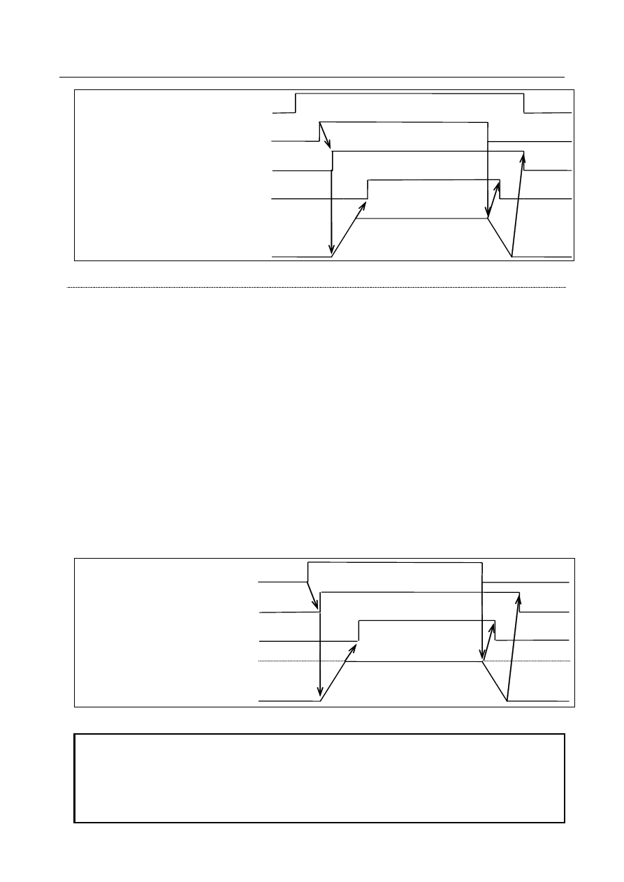
Fig. 10.22.1 (c) Timing chart of signals during servo motor spindle control 


Servo motor spindle synchronization 

Can rotate the servo motor in synchronization with the feedback pulses from the position coder of the 
main-spindle. 
 

Servo motor spindle synchronization mode 

By setting the servo motor spindle synchronization start signal SYSS  <Gn061.2> to “1”, the system 
enters servo motor spindle synchronization mode. When the system enters servo motor spindle 
synchronization mode, the servo motor accelerates or decelerates to the rotation speed of the main-spindle 
that is specified with parameter No. 3844. If a move command is commanded from the CNC  in 
acceleration/deceleration, alarm PS5211 “ILLEGAL AXIS OPERATION” is issued. Upon completion of 
acceleration/deceleration, the servo motor spindle synchronization mode acceleration/deceleration 
completion signal SYAR <Fn090.4> is set to “1”. Then the servo motor rotates in synchronization with 
the feedback pulses from the position coder. 
When the system enters servo motor spindle synchronization mode, the servo motor spindle 
synchronization mode signal SYSSM <Fn090.5> is set to “1”. 
By setting SYSS to “0”, servo motor spindle synchronization mode is canceled. If a rotation command is 
being executed with servo motor spindle control, the sub-spindle accelerates or decelerates to the speed 
specified  at that point. Upon completion of the cancellation of servo motor spindle synchronization, 
SYSSM is set to “0”. 


Spindle speed 


Servo motor rotation 

Servo motor spindle synchronization mode 

acc./dec. completion signal SYAR (output) 

Servo motor spindle synchronization   

mode signal SYSSM (output) 

Servo motor spindle synchronization   

start signal SYSS (input) 

Fig. 10.22.1 (d) Timing chart of signals during servo motor spindle synchronization 


NOTE 

1  In servo motor spindle synchronization mode, coordinates will not be updated. 

Thus, the relationships between coordinates and actual machine position will be 
lost. That is, the updating of coordinates with NC commands in servo motor 
spindle synchronization mode does not represent the actual movements of the 
machine. 

B-64693EN-1/01


10. SPINDLE SPEED FUNCTION


- 1851 - 

NOTE 

2  At the start or end of servo motor spindle synchronization mode, all servo axes 

except sub-spindles must be stopped. 

3  To start or cancel servo motor spindle synchronization mode during automatic 

operation, be sure to specify an M code that does not perform buffering before 
and after switching modes. 

4  In servo motor spindle synchronization mode, nano interpolation is disabled on 

sub-spindles. 

5  In servo motor spindle synchronization mode, do not use the torque control or 

speed control of PMC axis control on sub-spindles. 


Relationships with servo motor spindle control mode 

In servo motor spindle synchronization mode, rotation commands due to servo motor spindle control 
commands are disabled. By setting SYSS to 0, servo motor spindle control commands are enabled. 
 

Differential speed synchronization 

Can superimpose a move command from the CNC or the rotation speed specified with an input signal on 
the servo motor in servo motor spindle synchronization mode. It cannot superimpose both of them at the 
same time. 
 

Superimposition of a move command 

If a move command is executed on the servo axis in servo motor spindle synchronization mode, the move 
command is superimposed on the synchronization speed. 
 

Superimposition of the rotation speed from an input signal 

By setting the differential speed synchronization command signal DFSYC <Gn022.4> and the servo 
motor spindle switching signal SVSP to “1”  in servo motor spindle synchronization mode, SVR01I  to 
SVR12I  and SVGN become effective, so that the servo motor rotates at the speed resulting from 
synthesizing the speed specified with SVR01I to SVR12I and the speed at which to synchronize with the 
feedback from the position coder. 
If  a move command is commanded from the CNC on the servo motor in servo motor spindle 
synchronization  mode  when DFSYC and SVSP signals set to “1”, alarm PS5211 “ILLEGAL AXIS 
OPERATION” is issued. 
 

Relationships with Servo motor spindle control and Servo motor synchronous 
control 

In servo motor spindle synchronization mode, rotation commands due to servo motor spindle control 
commands are disabled. (When servo motor synchronous control is performed during servo motor spindle 
control mode, servo motor spindle control mode is canceled). 
By one of the followings, servo motor spindle control commands are enabled again. 
    - Differential speed synchronization mode is enabled (Change DFSYC from "0" to "1")   
    - Servo motor synchronous control is canceled (Change SYSS from "1" to "0") 

10. SPINDLE SPEED FUNCTION


B-64693EN-1/01


- 1852 - 


Main Spindle speed 

SV/SP control mode  

acc./dec. completion  

signal SVAR(output) 

SV/SP control mode  

signal SVSPM(output) 

SV/SP switching signal 

SVSP(input) 

SV/SP synchronization mode 

acc./dec. completion 

signal SYAR(output) 

SV/SP synchronization mode 

signal SYSSM(output) 

Servo motor rotaion 

Differential speed 

synchronization command 

signal DFSYC(input) 

SV/SP synchronization 

start signal SYSS(input) 

Fig.10.22.1 (e) Timing chart of signals related to servo motor spindle control 


Feed forward 

During servo spindle control and servo spindle synchronization, the function of feed forward with a servo 
motor can be enabled. Enabling the feed forward function has the effect of preventing delays due to servo 
errors when differential speed commands are issued. 
 

Signal 

Servo motor spindle control switching signal SVSP <Gn022.7> 

  [Classification]  Input signal 
 

[Function]  By setting SVSP  to  “1”, the system enters servo motor spindle control mode, so that a 

command is executed on the servo motor at the rotation speed previously set in the 12 bits 
of SVR1I to SVR12I. If this occurs, SVSPM is set to “1”. 
By setting SVSP  to  “0”, servo motor spindle control mode is canceled. If this occurs, 
SVSPM is set to “0”. 


NOTE 


In servo motor spindle control mode, coordinates will not be 
updated. Thus, the relationships between coordinates and actual 
machine position will be lost. 


Servo motor spindle control mode signal SVSPM <Fn090.7> 

  [Classification]  Output signal 
 

[Function]  This signal notifies that the system is in servo motor spindle control mode. 


[Output cond.]  This signal is set to “1” when the system enters servo motor spindle control mode. 


Servo motor rotation speed specification signals SVR01I to SVR12I <Gn021.0 to 
Gn022.3> 

  [Classification]  Input signal 

B-64693EN-1/01


10. SPINDLE SPEED FUNCTION


- 1853 - 


[Function]  These signals enable specification of the rotation speed of the servo motor during servo 

motor spindle control by setting the setting determined from the formula below, in binary 
notation. 

4095

No.3842)

meter 

motor(para


spindle


of


speed


Maximum

motor


spindle


of


Speed

×

=

Setting


Servo motor rotation polarity specification signal SVGN <Gn022.5> 

  [Classification]  Input signal 
 

[Function]  This signal specifies the rotation direction of the servo motor. 

0: 

The polarity is plus. 

1: 

The polarity is minus. 


Servo motor spindle control mode acceleration/deceleration completion signal 
SVAR <Fn090.6> 

  [Classification]  Output signal 
 

[Function]  This signal notifies that servo motor acceleration/deceleration has ended in servo motor 

spindle control. 


[Output cond.]  This signal is set to “1”  at the end of acceleration/deceleration in servo motor spindle 

control mode. 


Servo motor spindle synchronization start signal SYSS <Gn061.2> 

  [Classification]  Input signal 
 

[Function]  By setting SYSS to “1”, the system enters servo motor spindle synchronization mode. If 

this occurs, SYSSM is set to “1”. 
When the system enters servo motor spindle synchronization mode, the sub-spindle 
accelerates or decelerates to the rotation speed of the main spindle. Then, the sub-spindle 
rotates in synchronization with the feedback pulses from the position coder of the main 
spindle. 
By setting SYSS  to  “0”, servo motor spindle synchronization mode is canceled. If a 
rotation command is being executed with servo motor spindle control, the sub-spindle 
accelerates or decelerates to the speed specified at that point. Upon completion of the 
cancellation of servo motor spindle synchronization, SYSSM is set to “0”. 
In servo motor spindle synchronization mode, rotation commands due to servo motor 
spindle control commands are disabled. By setting SYSS  to  “0”, servo motor spindle 
control commands are enabled. 


NOTE 


In servo motor spindle synchronization mode, coordinates will not 
be updated. Thus, the relationships between coordinates and 
actual machine position will be lost. That is, the updating of 
coordinates with NC commands in servo motor spindle 
synchronization mode does not represent the actual movements of 
the machine. 


Servo motor spindle synchronization mode signal SYSSM <Fn090.5> 

  [Classification]  Output signal 
 

[Function]  This signal notifies that the system is in servo motor spindle synchronization mode. 


[Output cond.]  This signal is set to “1”  when the system enters servo motor spindle synchronization 

mode. 


Servo motor spindle synchronization mode acceleration/deceleration completion 
signal SYAR <Fn090.4> 

  [Classification]  Output signal 

10. SPINDLE SPEED FUNCTION


B-64693EN-1/01


- 1854 - 


[Function]  This signal notifies that servo motor acceleration/deceleration has ended in servo motor 

spindle synchronization. 


[Output cond.]  This signal is set to “1”  at the end of acceleration/deceleration in servo motor spindle 

synchronization mode. 


Differential speed synchronization command signal DFSYC <Gn022.4> 

  [Classification]  Input signal 
 

[Function]  This signal enables superimposing of rotation commands due to servo motor spindle 

control in servo motor spindle synchronization mode. 


Signal address 


#7 

#6 

#5 

#4 

#3 

#2 

#1 

#0 

Gn021 


SVR08I

#p


SVR07I

#p


SVR06I

#p


SVR05I

#p


SVR04I

#p


SVR03I

#p


SVR02I

#p


SVR01I

#p


Gn022 


SVSP

#P


SVGN

#p


DFSYC

#P


SVR12I

#p


SVR11I

#p


SVR10I

#p


SVR09I

#p


Gn061 


SYSS

#P


#7 

#6 

#5 

#4 

#3 

#2 

#1 

#0 

Fn090 


SVSPM

#P 

SVAR

#P 

SYSSM

#P 

SYAR

#P 


Parameter 

3841 


Servo motor spindle control axis number 


[Data type]  Word 

[Valid data range] 1 to 24 

This parameter sets the axis number of an axis to be subject to servo motor spindle 
control or servo motor spindle synchronization. 
Setting the parameter to 0 disables servo motor spindle control and servo motor spindle 
synchronization. 
For servo motor spindle synchronization, you have to set bit 4 (SPSx) of parameter No. 
2016. 
 

3842 


Maximum speed for servo motor spindle control 


[Data type]  2-word 


[Unit of data]  min

-1


[Valid data range] 0 to 9999 

This parameter sets the maximum speed of the spindle to be subject to servo motor 
spindle control. 
 

3843 


Time constant for acceleration/deceleration under servo motor spindle control 


[Data type]  Word 


[Unit of data]  msec 

[Valid data range] 0 to 4000 

This parameter sets the time constant for acceleration/deceleration under servo motor 
spindle control and servo motor spindle synchronization. 
The type of acceleration/deceleration is linear acceleration/deceleration. 
Set the parameter to the time to be taken for the spindle speed to reach 1000 (min

-1

). 


3844 


Master spindle number 


[Data type]  Word 

B-64693EN-1/01


10. SPINDLE SPEED FUNCTION


- 1855 - 

[Valid data range] 0 to 104 

Set the number of the spindle (position coder) to be subject to servo motor spindle 
synchronization. 
The hundreds and tens digits represent a path; the units digit represents the number of the 
position coder in the path. 
To synchronize the servo axis in the second path and the second position coder in the first 
path under dual-path control, for example, set this parameter for the second path to 12. 
When the hundreds and tens digits are both 0, the local path is assumed. 
When a value of 0 is specified, the first position coder in the local path is assumed. 
 

  WARNING 

1  The combination of the position coder and servo motor to be 

synchronized with each other is determined by wire connection. 
Even though you change the setting of this parameter, therefore, 
you cannot change the combination of the position coder and servo 
motor to be synchronized with each other. 

2  This parameter is used for acceleration or deceleration to be 

performed when the synchronization mode is turned on/off. 

3  It is dangerous to set a value not matching the actually 

wire-connected combination as it prevents correct 
acceleration/deceleration. Be sure to set a value matching the 
actual wire connection. 


#7 

#6 

#5 

#4 

#3 

#2 

#1 

#0 

2003 


PIENx 


[Data type]  Bit axis 


#3  PIENx

  PI control is: 

0: 

Disabled. 

1: 

Enabled. 


NOTE 


This bit must be set to use the feed forward function. 


#7 

#6 

#5 

#4 

#3 

#2 

#1 

#0 

2005 


FEEDx 


[Data type]  Bit axis 


#1  FEEDx

  Feed forward function is: 

0: 

Disabled. 

1: 

Enabled. 


NOTE 

1  This bit must be set to use the feed forward function. 
2  This parameter is initial setting parameter. For details, refer to the 

appendix "Automatic setting / Initial setting parameter" in this 
manual. 


#7 

#6 

#5 

#4 

#3 

#2 

#1 

#0 

2011 


FFALx 


10. SPINDLE SPEED FUNCTION


B-64693EN-1/01


- 1856 - 


[Data type]  Bit axis 


#1  FFAL

x

  Feed-forward control is: 

0: 

Enabled only in normal cutting feed during automatic operation when parameter 
No.1800#3 is set to 0. 
Enabled in normal cutting feed and rapid traverse during automatic operation when 
parameter No.1800#3 is set to 1. 

1: 

Always enabled regardless of the mode. 


NOTE 


This bit must be set to use the feed forward function on Servo/ 
spindle synchronization. 


#7 

#6 

#5 

#4 

#3 

#2 

#1 

#0 

2016 


SPSx 


[Data type]  Bit axis 


#4  SPS

x

  Servo motor spindle synchronization is: 

0: 

Disabled. 

1: 

Enabled. 


NOTE 


Be sure to set this bit to perform servo spindle synchronization. 


2038 


Spindle feedback magnification (R) 


[Data type]  Word 

[Valid data range] 

±

32737 

Set a magnification so that the number of feedback pulses from the position coder of the 
main spindle during servo motor spindle synchronization will be 4096 per rotation of the 
spindle. 

Setting= 

Gear of spindle 

Gear of position coder 

 
If the setting is 0, synchronous control is not performed. 
The rotation direction of the servo motor changes with the sign of the setting. 


2068 


Feed forward coefficient 


[Data type]  Word 

[Valid data range]  0 to 10000 

Setting = 

α x 100 


NOTE 


To use the feed forward function, this parameter must be set. 


2069 


Velocity feed forward coefficient 


[Data type]  Word 

[Valid data range]  50 to 200 

This parameter adjusts follow-up capability if it is poor. 


B-64693EN-1/01


10. SPINDLE SPEED FUNCTION


- 1857 - 

NOTE 


To use the feed forward function, this parameter must be set. 


2084 


Flexible feed gear (numerator) (M) 


2085 


Flexible feed gear (denominator) (N) 


[Data type]  Word axis 

[Valid data range]  0 to 32767 

Set the flexible feed gear so that the command per rotation of the spindle will be 4096. 


24096 


Connector number for the first or ninth separate detector interface unit 


24097 


Connector number for the second or tenth separate detector interface unit 


24098 


Connector number for the third or eleventh separate detector interface unit 


24099 


Connector number for the fourth or twelfth separate detector interface unit 


24100 


Connector number for the fifth separate detector interface unit 


24101 


Connector number for the sixth separate detector interface unit 


24102 


Connector number for the seventh separate detector interface unit 


24103 


Connector number for the eighth separate detector interface unit 


NOTE 


When these parameters are set, the power must be turned off before 
operation is continued. 


[Input type]  Parameter input 


[Data type]  Byte axis 

[Valid data range]  0 to 8 

Set a connector number for the connector to which a separate detector interface unit is 
attached if the separate detector interface unit is to be used. The following table lists the 
necessary settings. Be sure to specify 0 for connectors not in use. 
 

Correspondence between connectors and connector numbers 

Connector 

Connector number 

JF101 

JF102 

JF103 

JF104 

JF105 

JF106 

JF107 

JF108 

 
(Setting example) 

Controlled 

axis 

Connector to which each separate 

detector interface unit is attached 

Parameter setting 

1st 

connector 

2nd 

connector 

5th 

connector 

6th 

connector 

No. 

24096 

No. 

24097 

No. 

24100 

No. 

24101 

X1 

JF101 


Y1 


JF102 


Z1 


JF102 


Content      ..     235      236      237      238     ..