FANUC Series 0i-MODEL F Plus. CONNECTION MANUAL (FUNCTION) - page 221
 

  Index      Manuals     FANUC Series 0i-MODEL F Plus. CONNECTION MANUAL (FUNCTION) B-64693EN-1/01


Search            copyright infringement  


Content      ..     219      220      221      222     ..


FANUC Series 0i-MODEL F Plus. CONNECTION MANUAL (FUNCTION) - page 221


10. SPINDLE SPEED FUNCTION


B-64693EN-1/01


- 1722 - 

Logic spindle number common to system 

Path number + intra-path spindle number 

Fifth spindle (S5) 

First spindle of path 2 (S21) 

Sixth spindle (S6) 

Second spindle of path 2 (S22) 


Path 1

Path 2

Spindle S1
(S11)

Spindle S2
(S12)

Spindle S3
(S13)

Spindle S4
(S14)

Spindle S5
(S21)

Spindle S6
(S22)


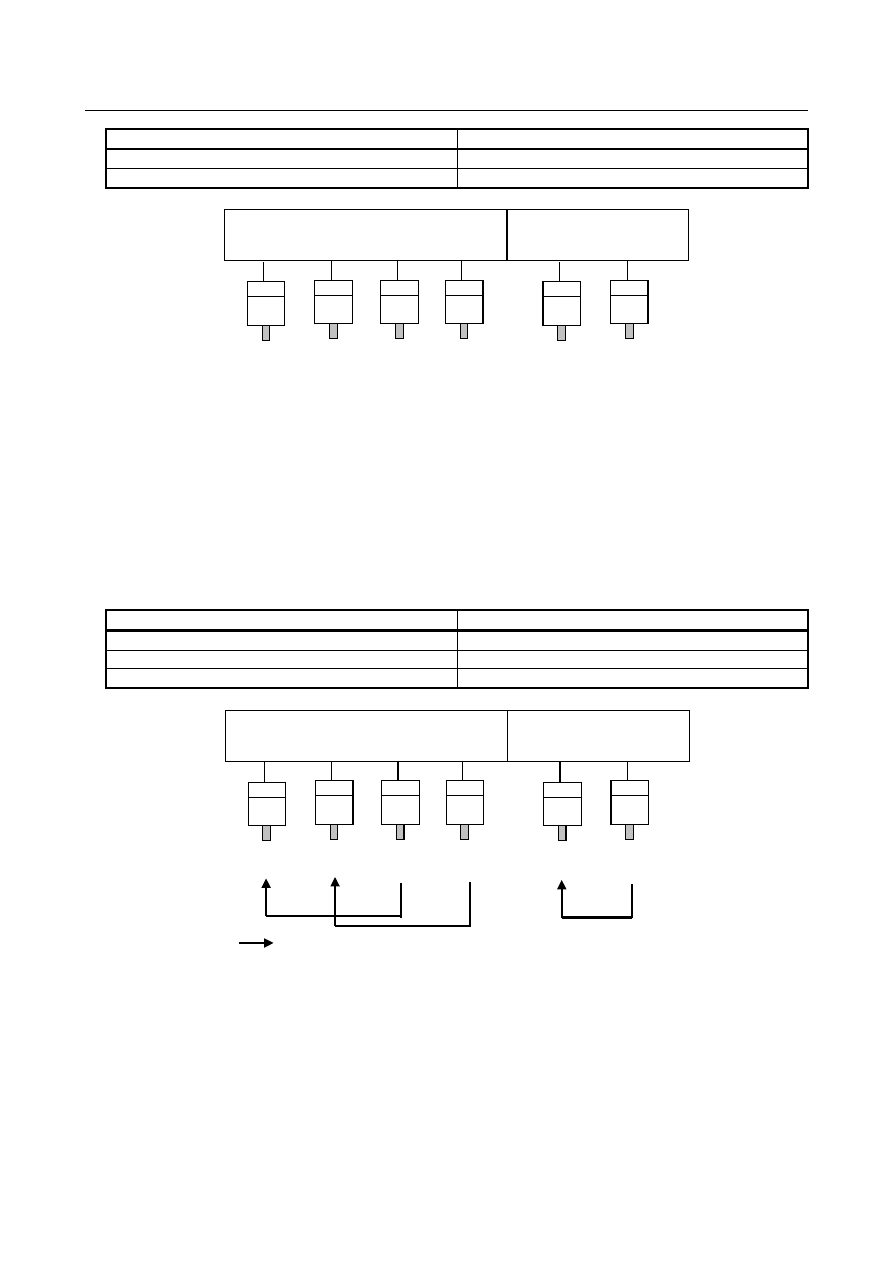
Example 1: 
 

Combining spindles of the same path for spindle synchronization 


Parameter setting 


Bit 4 (SSS) of parameter No.3704 (PATH1)=1, (PATH2)=1 


Parameter No.4831(S1) =0, (S2) =0,(S3) =1,(S4) =2,(S5) =0,(S6) =1 


Parameter No.4832(ALL) =0 


or 


Parameter No.4831(ALL) =0 


Parameter No.4832(S1) =0, (S2) =0,(S3) =1,(S4) =2,(S5) =0,(S6) =5 


Master spindle 

Slave spindle 

First spindle of path 1 (S11) 

Third spindle of path 1 (S13) 

Second spindle of path 1 (S12) 

Fourth spindle of path 1 (S14) 

First spindle of path 2 (S21) 

Second spindle of path 2 (S22) 


Path 1

Path 2

Spindle S1
(S11)

Spindle S2
(S12)

Spindle S3
(S13)

Spindle S4
(S14)

Spindle S5
(S21)

Spindle S6
(S22)

Master spindle with which slave spindle is synchronized


Example 2: 
 

Combining spindles of different paths for spindle synchronization 


Parameter setting 


Bit 4 (SSS) of parameter No.3704 (PATH1)=1, (PATH2)=1 


Parameter No.4831(ALL) =0 


Parameter No.4832(S1) =0, (S2) =0,(S3) =0,(S4) =0,(S5) =1,(S6) =2 


B-64693EN-1/01


10. SPINDLE SPEED FUNCTION


- 1723 - 

Master spindle 

Slave spindle 

First spindle of path 1 (S11) 

First spindle of path 2 (S21) 

Second spindle of path 1 (S12) 

Second spindle of path 2 (S22) 


Path 1

Path 2

Spindle S1
(S11)

Spindle S2
(S12)

Spindle S3
(S13)

Spindle S4
(S14)

Spindle S5
(S21)

Spindle S6
(S22)

Master spindle with which slave spindle is synchronized


When the bit 5 (SCB) of parameter No.4800 is set to 1 


The configuration of synchronized spindles is as follows (regardless of the setting of bit 4 (SSS) of 
parameter No.3704): 


Master spindle 

Slave spindle 

First spindle of path 1 

First spindle of path 2 


Path 1 

Path 2 

Spindle S1 
(S11) 


Spindle S2 
(S12) 


Spindle S3 
(S13) 


Spindle S4 
(S14) 


Spindle S5 
(S21) 


Spindle S6 
(S22) 


Master spindle with which slave spindle is synchronized 


As control signals, the 16TT system compatible signal interface becomes usable. 


  - 

Speed synchronization 

When the spindle synchronous control signal is set to “1”, the spindle synchronous control mode is 
set. 


When spindle synchronous control is specified, each spindle is accelerated or decelerated to a 
specified speed then enters the synchronous control state. 

The spindle synchronous speed control completion signal is output when the two spindles have 
reached the speed matching a specified spindle synchronous speed and the speed difference between 
the two spindles is within the value set in parameter No.4033. 


  - 

Phase matching 

Spindle phase synchronization is executed by setting the spindle phase synchronization control 
signal to 1 in the spindle synchronous control mode (after the output of the spindle synchronous 
speed control completion signal). 


The synchronous state between the two axes is not maintained during spindle phase synchronization 
operation (until the spindle phase synchronization control completion signal is set to 1). 

10. SPINDLE SPEED FUNCTION


B-64693EN-1/01


- 1724 - 

The spindle phase synchronization completion signal is output when the error difference between the 
two spindles lies within the allowable number of pulses set in the NC parameter No. 4810. 


If spindle phase synchronization is specified after spindle phase synchronization completion, another 
spindle phase synchronization operation is performed. 


When the two spindles hold a workpiece, do not specify spindle phase synchronization.   


  - 

Speed specification 

In the spindle synchronous control mode, the specification of a speed for the master spindle is valid. 

In the spindle synchronous control mode, a speed for the master spindle can be specified in the same 
way as for an ordinary S command. 


Moreover, signals such as the PMC-based spindle output control signals (SIND, SSIN, SSGN, and 
R01I to R12I), *SSTP, and SOR are valid as usual. 


If a speed is specified using a PMC-based spindle output control command, however, the parameters 
Nos. 3741, 3742, 3743, and 3744 for specifying the maximum speeds of the individual spindle gears 
must be correctly set beforehand. 


When 0 is set in the parameter corresponding to a selected gear, the spindle does not make a 
synchronous rotation. 

An S command specified for a master spindle and a speed specified for PMC-based spindle output 
control before the spindle synchronous control mode is set are valid even in the spindle synchronous 
control mode. 


A speed command for a master spindle during spindle synchronous control is also valid as a 
command for the master spindle after spindle synchronous control is canceled. 


  - 

Speed ratio control 

Spindle synchronous control can be exercised to set a speed ratio of master spindle: slave spindle to 
1:n. 


Speed ratio control is exercised in spindle synchronization by setting the spindle synchronous speed 
ratio control signal SBRT <Gn038.1> to “1” in the spindle synchronous control mode. At this time, 
the speed ratio of master spindle: slave spindle is 1:n (n: value set in the parameter No.7635). 


Path 1

Path 2

Spindle S1
(S11)

Spindle S2
(S12)

Spindle S3
(S13)

Spindle S4
(S14)

Spindle S5
(S21)

Spindle S6
(S22)

Master spindle with which slave spindle is synchronized


Mater spindle : Speed ratio setting for the slave spindle 1:2 
When the speed S100 is specified for master spindle S1 
Spindle S1 : Spindle speed S100(1/min) 
Spindle S2 : Placed in synchronous control state with spindle speed S200 (1/min). 
 
If the speed of each slave spindle specified by multiplying the speed specified for the master spindle by a 
speed ratio exceeds the value set in the parameter No.7636, the speed of each slave spindle is clamped to 
a set maximum allowable speed. At the same time, the speed of the master spindle is clamped to the speed 
that maintains the speed ratio. 
When the speeds of multiple slave spindles are clamped, all spindles are clamped to the speeds that can 
maintain the speed ratios for synchronization control. 

B-64693EN-1/01


10. SPINDLE SPEED FUNCTION


- 1725 - 

When the speed of a slave spindle is clamped, the spindle synchronous speed ratio control clamp signal 
RSMAX <Fn065.2> is set to “1”. 
 

  - 

Supplement 

To monitor an error mutually between two spindles in the spindle synchronous control mode, the 
spindle  phase error monitor signal SYCAL <Fn044.4> (SYCAL1 to SYCAL4 <Fn043.0> to 
<Fn043.3>) is available. A synchronization error between two spindles is monitored at all times. 
When a synchronization error exceeding the value (absolute number of error pulses) set in parameter 
No.4811 is detected, this signal is set to “1”. When the synchronization error does not exceed the 
value set in parameter No.4811, the signal is set to “0”. 

Even when two spindles hold a workpiece in the synchronous control state, constant surface speed 
control can be exercised. Even if the speed of a spindle changes, however, the synchronous speed 
changes within the parameter-set range (acceleration/deceleration time constant in spindle 
synchronous control). 

In spindle synchronous control, the spindle speed offset value (parameter No.3731) is invalid. 

 
For details of synchronous-spindle connection, see the description of serial spindles. 
 

Limitation 

When spindles are placed in a mode other than a spindle rotation mode such as the Cs contouring 
control mode, rigid tapping, and spindle command synchronous, the spindle synchronous control 
mode cannot be used. In the spindle rotation mode, switch the mode of the master and slave spindles 
to the spindle synchronous control mode. 

For spindles placed in the spindle synchronous control mode, commands for Cs contouring control, 
rigid tapping, spindle command synchronous, and so forth cannot be specified. 

The maximum speed in spindle synchronous control depends on the maximum speed (parameter No. 
4020) of the spindle motor of the master spindle. 
Example) 
 

Maximum speed of the spindle motor of a master spindle:  6000 min

-1


Maximum speed of the spindle motor of a slave spindle: 

4500 min

-1


In the example above, 6000 min

-1

 is specified as the maximum speed of the master spindle for 12bit 

= 4095. However, when 6000 min

-1

 is specified in spindle synchronous control, the excessive-speed 

alarm (spindle unit side alarm AL-07) is issued with the slave spindle. 


So, do not specify a speed exceeding 4500 min

-1

 in the example above. 


Diagnosis data 

0418 


Position deviation of each spindle 

 
When spindles are involved in a position loop, the position deviation of each spindle is indicated. 
The unit of a detector used in each mode is used. 
 

0425 


Synchronization error of each spindle 

 
The absolute value of the synchronization error of each spindle in spindle synchronization is indicated. 
A synchronization error is indicated with a slave spindle. 
 

Spindle tuning screen (spindle synchronous control) 

In the spindle synchronous control mode, the spindle tuning screen displays the information below. 
"Spindle position deviation" indicates the position deviation of the spindle currently displayed. 
"Synchronous deviation  " indicates the absolute value of a synchronization error in spindle 
synchronization. The value of a synchronization error is displayed on the spindle tuning  screen for the 
slave spindle. 
When bit 3 (SVP) of parameter No.3799 is set to 1, "synchronous deviation"  indicates the peak hold 
value of a synchronization error. 

10. SPINDLE SPEED FUNCTION


B-64693EN-1/01


- 1726 - 

For details, refer to Spindle tuning screen of MAINTENANCE MANUAL (B-64695EN). 
 

Motor speed 
Spindle speed 
Spindle position deviation S1 
Spindle position deviation S2 
Synchronous deviation 


Signal 

Spindle synchronous control signal SPSYC<Gn038.2> 

  [Classification]  Input signal 
 

[Function]  This signal specifies switching to the spindle synchronous control mode for the 

first/second spindles. 


[Operation]  When this signal is set to “1”, the spindle synchronous control mode for the first/second 

spindles is set. 
When this signal is set to “0”, the spindle synchronous control mode for the first/second 
spindles is canceled. 
 
This signal is valid only when bit 4 (SSS) of parameter No.3704 is set to 0. 
When bit 5 (SCB) of parameter No.4800 is set to 1, an address of n = 0 is valid. 


Spindle synchronous control signal of each spindle   

SPSYC1 to SPSYC4<Gn288.0 - Gn288.3> 

  [Classification]  Input signal 
 

[Function]  These signals specify the switching of each spindle to the spindle synchronous control 

mode. 


[Operation]  When each of these signals is set to “1”, the spindle synchronous control mode with a 

spindle set as a slave spindle is set. 
When each of these signals is set to “0”, the spindle synchronous control mode with a 
spindle set as a slave spindle is canceled. 
When SPSYCs is set to “1”, spindle synchronization with a spindle set as a slave spindle 
is performed. 
 
These signals are valid only when bit 4 (SSS) of parameter No.3704 is set to 1 and bit 5 
(SCB) of parameter No.4800 is set to 0. 
Which spindle is synchronized with which spindle is set using parameter No.4831 or 
4832. 
 

NOTE 


For the correspondence between the signal of each spindle and 
actual signal address, see the description of "Signal address". 


Spindle phase synchronization control signal SPPHS<Gn038.3> 

  [Classification]  Input signal 
 

[Function]  This signal specifies the spindle phase synchronization control mode (phase matching) for 

the first/second spindles. 


[Operation]  When this signal makes a transition from “0” to “1”, spindle phase synchronization 

control for the first/second spindles is exercised. 
This signal is valid when the spindle synchronous control signal SPSYC is set to “1”. 
Specify this signal after the spindle synchronous speed control completion signal FSPSY 
is set to “1”. 
A spindle phase synchronization control operation is started on the rising edge of this 
signal. 

B-64693EN-1/01


10. SPINDLE SPEED FUNCTION


- 1727 - 

So, phase matching once performed is not lost when this signal is set to “0”. 
However, when this signal is set to  “1” from “0” again, a phase matching operation is 
performed. 
 
This signal is valid only when bit 4 (SSS) of parameter No.3704 is set to 0. 
Set a phase shift amount in parameter No.4034. 
When bit 5 (SCB) of parameter No.4800 is set to 1, an address of n = 0 is valid. 
 

NOTE 


Before specifying this signal, ensure that the spindle synchronous 
speed control completion signal FSPSY is set to “1”. When the 
spindle synchronous speed control completion signal FSPSY is set 
to “0”, phase matching operation is not performed. 


Spindle phase synchronization control signal of each spindle   

SPPHS1 to SPPHS4<Gn289.0 to Gn289.3> 

  [Classification]  Input signal 
 

[Function]  These signals specify the spindle phase synchronization control mode (phase matching) 

for each spindle. 


[Operation]  When each of these signals is set to “1”, spindle phase matching is performed in the 

spindle synchronous control mode with a spindle set as a slave spindle. 
These signals are valid when the spindle synchronous control signal SPSYCs for each 
spindle is set to “1”. 
Specify each of these signals after the spindle synchronous speed control completion 
signal FSPSYs for each spindle is set to “1”. 
A spindle phase synchronization control operation is started on the rising edge of each of 
these signals. 
So, phase matching once performed is not lost when each of these signals is set to “0”. 
However, when each of these signals is set to “1” from “0” again, a phase matching 
operation is performed. 
 
These signals are valid only when bit 4 (SSS) of parameter No.3704 is set to 1 and bit 5 
(SCB) of parameter No.4800 is set to 0. 
Set a phase shift amount in parameter No.4034. 
 

NOTE 

1  Before specifying these signals, ensure that the spindle 

synchronous speed control completion signal FSPSYx is set to “1”. 
When the spindle synchronous speed control completion signal 
FSPSYx is set to “0”, phase matching operation is not performed. 

2  Phase matching in the state where spindles are rotating in 

synchronism is enabled only for one slave spindle synchronized with 
one master spindle. When phase matching is to be performed in the 
state where multiple slave spindles are rotating in synchronism with 
one master spindle, do not specify spindle phase synchronization 
control on multiple spindles. 

3  Before performing phase matching of one master spindle with 

multiple slave spindles, ensure that all spindles are stopped. 

4  For the correspondence between the signal of each spindle and 

actual signal address, see the description of "Signal address". 


10. SPINDLE SPEED FUNCTION


B-64693EN-1/01


- 1728 - 

Spindle synchronous speed control completion signal FSPSY<Fn044.2> 

  [Classification]  Output signal 
 

[Function]  This signal posts that spindle synchronous control (speed synchronization) for the 

first/second spindles is completed. 


[Output cond.]  This signal is set to “1” in the following case: 

This signal is output when two spindles have reached the speed equivalent to a 
specified spindle synchronous speed and the speed difference between the two 
spindles is equal to or less than the value set in parameter No.4033 in the spindle 
synchronous control mode. 

This signal is set to “0” in the following cases: 

In the spindle synchronous control mode, two spindles have not reached the speed 
equivalent to a specified spindle synchronous speed. 

In the spindle synchronous control mode, the speed difference between two spindles 
is greater than the value set in parameter No.4033. 

The spindle synchronization control mode is not set. 

 
This signal is valid only when bit 4 (SSS) of parameter No.3704 is set to 0. 
When bit 5 (SCB) of parameter No.4800 is set to 1, an address of n = 0 is valid. 


NOTE 


Even if this signal is once set to “1”, this signal is set to “0” when 
the speed difference exceeds the value set in parameter No.4033 
for a cause such as cutting load variation. 


Spindle synchronous speed control completion signal for each spindle   

FSPSY1 to FSPSY4<Fn288.0 to Fn288.3> 

  [Classification]  Output signal 
 

[Function]  These signals post that spindle synchronous control (speed synchronization) with each 

spindle set as a slave spindle is completed. 


[Output cond.]  This signal is set to “1” in the following case: 

This signal is output when two spindles have reached the speed equivalent to a 
specified spindle synchronous speed and the speed difference between the two 
spindles is equal to or less than the value set in parameter No.4033 in the spindle 
synchronous control mode. 

This signal is set to “0” in the following cases: 

In the spindle synchronous control mode, two spindles have not reached the speed 
equivalent to a specified spindle synchronous speed. 

In the spindle synchronous control mode, the speed difference between two spindles 
is greater than the value set in parameter No.4033. 

The spindle synchronization control mode is not set. 


These signals are valid only when bit 4 (SSS) of parameter No.3704 is set to 1 and bit 5 
(SCB) of parameter No.4800 is set to 0. 
 

NOTE 

1  Even if this signal is once set to “1”, this signal is set to “0” when 

the speed difference exceeds the value set in parameter No.4033 
for a cause such as cutting load variation. 

2  For the correspondence between the signal of each spindle and 

actual signal address, see the description of "Signal address". 


B-64693EN-1/01


10. SPINDLE SPEED FUNCTION


- 1729 - 

Spindle phase synchronization control completion signal FSPPH<Fn044.3> 

  [Classification]  Output signal 
 

[Function]  This  signal posts that spindle phase synchronization control (phase matching) for the 

first/second spindles is completed. 


[Output cond.]  This signal is set to “1” in the following case: 

This signal is output when phase matching is completed with the spindle phase 
synchronization control signal (when the error pulse difference between the two 
spindles is equal to or less than the value set in parameter No.4810) after the two 
spindles have reached the speed equivalent to a specified spindle synchronous speed 
in the spindle synchronous control mode. 

This signal is set to “0” in the following cases: 

In the spindle synchronous control mode, the phase matching of two spindles is not 
completed. 

In the spindle synchronous control mode, the error pulse difference between two 
spindles is greater than the value set in parameter No.4810. 

The spindle synchronous control mode is not set. 

The spindle phase synchronization control mode is not set. 

 
This signal is valid only when bit 4 (SSS) of parameter No.3704 is set to 0. 
When bit 5 (SCB) of parameter No.4800 is set to 1, an address of n = 0 is valid. 
 

NOTE 


Even if this signal is once set to “1”, this signal is set to “0” when 
the speed difference exceeds the value set in parameter No.4810 
for a cause such as cutting load variation. 


Spindle phase synchronization control completion signal of each spindle   

FSPPH1 to FSPPH4<Fn289.0 to Fn289.3> 

  [Classification]  Output signal 
 

[Function]  These signals post that spindle phase synchronization control (phase matching) with each 

spindle set as a slave spindle is completed. 


[Output cond.]  This signal is set to “1” in the following case: 

This signal is output when phase matching is completed with the spindle phase 
synchronization control signal (when the error pulse difference between the two 
spindles is equal to or less than the value set in parameter No.4810) after the two 
spindles have reached the speed equivalent to a specified spindle synchronous speed 
in the spindle synchronous control mode. 

This signal is set to “0” in the following cases: 

In the spindle synchronous control mode, the phase matching of two spindles is not 
completed. 

In the spindle synchronous control mode, the error pulse difference between two 
spindles is greater than the value set in parameter No.4810. 

The spindle synchronous control mode is not set. 

The spindle phase synchronization control mode is not set. 

 
These signals are valid only when bit 4 (SSS) of parameter No.3704 is set to 1 and bit 5 
(SCB) of parameter No. 4800 is set to 0. 


Content      ..     219      220      221      222     ..