FANUC Series 0i-MODEL F Plus. CONNECTION MANUAL (FUNCTION) - page 192
 

  Index      Manuals     FANUC Series 0i-MODEL F Plus. CONNECTION MANUAL (FUNCTION) B-64693EN-1/01


Search            copyright infringement  


Content      ..     190      191      192      193     ..


FANUC Series 0i-MODEL F Plus. CONNECTION MANUAL (FUNCTION) - page 192


10. SPINDLE SPEED FUNCTION


B-64693EN-1/01


- 1490 - 

Item No. 0000 (SPEED ARRIVAL ON) on the diagnosis screen is kept at 1 while this function is keeping 
the cutting feed block at a halt. 
 

Reading actual spindle speeds by PMC window 

The actual speed of the serial spindles can be read by PMC window (function code 138). Actual spindle 
speed is calculated by multiplying the ratio of the gear and motor speed. The gear which is in use is 
distinguished by the following signals. 
 

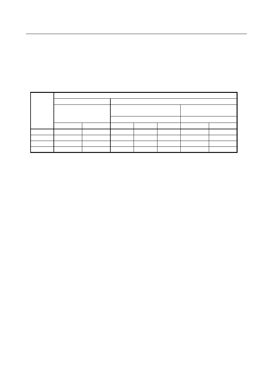
Table 10.5 (d) Gear selection status 

Gear 

number 

Bit 1 (SLG) of parameter No.3787 

Clutch/gear signals 

(serial spindle) 

M type 

gear selection method 

T type 

gear selection method 

Gear selection signals 

Gear selection signals 

CTH1 

CTH2 

GR3O 

GR2O 

GR1O 

GR2 

GR1 

"0" 

"0" 

"0" 

"0" 

"1" 

"0" 

"0" 

"0" 

"1" 

"0" 

"1" 

"0" 

"0" 

"1" 

"1" 

"0" 

"1" 

"0" 

"0" 

"1" 

"0" 

"1" 

"1" 

"1" 

"1" 


  - 

Analog spindle 


  Gain and offset 

The analog spindle may require gain and offset voltage adjustment depending on the spindle motor speed 
amplifier being used. 
The following parameters are available for such adjustment. 

Gain adjustment data: Parameter No. 3730 
Offset voltage compensation: Parameter No. 3731 


  Spindle enable signal ENB<Fn001.4> 

Another output related to spindle control is the spindle enable signal ENB. 
The ENB signal is logical “1” when a nonzero command output is sent to the spindle. If the command is 
logical 0, the ENB signal becomes logical “0”. 
When the analog spindle is being used, an offset voltage in the spindle motor speed amplifier may cause 
the spindle motor to rotate at low speed even if the command output (in this case, analog voltage) to the 
spindle is zero. The ENB signal can be used to stop the motor in such a case. 


  Electrical specification of analog spindle interface 

The ENB1/2 signal on the analog spindle interface is an interface signal that is turned on and off under 
the same conditions as of the spindle enable signal <Fn001.4>, and it can be used even when a serial 
spindle is used. 
For related signals on the analog spindle interface, refer to the description of the analog spindle interface 
in the section of the spindle connection in "Connection Manual (Hardware)". 
 

B-64693EN-1/01


10. SPINDLE SPEED FUNCTION


- 1491 - 

Signal 

Spindle stop signal *SSTP<Gn029.6> 

  [Classification]  Input signal 
 

[Function]  The command output to the spindle is disabled.   


[Operation]  When the spindle stop signal turns to “0”, the output voltage becomes 0V and the enable 

signal ENB turns to “0” (M05 is not output).   
When this signal turns to “1”, the analog voltage returns to its original value and the ENB 
signal turns to “1”. 


The above time chart is an example. Actually, the time chart should meet the specification 
of the spindle control unit. 

When this signal is not used, always set the signal to “1”. 

When the M03, M04, or M05 command is issued, the CNC outputs the code signal 
and strobe signal only. 


Spindle orientation signal SOR<Gn029.5> 

  [Classification]  Input signal 
 

[Function]  The spindle or the spindle motor is rotated at a constant 


[Operation]  When the spindle orientation signal turns to “1” and the spindle stop signal *SSTP turns 

to “0”, a spindle speed command which lets the spindle rotate at the constant speed set by 
parameter No. 3732 is output. The enable signal ENB also turns to “1”. This signal is 
disabled when the spindle stop signal is “1”.   
In the machining center system, when the spindle speed for orientation is set by bit 1 
(GST) of parameter No. 3705 and the SOR signal is input, the CNC outputs the spindle 
speed command corresponding to the speed set to parameter 3732 with an output polarity 
set by bit 5 (ORM) of parameter No. 3706, but the gear select signal does not change.   
For example, if the SOR signal is turned to 1 with high gear selected, and the speed set to 
parameter No. 3732 is in the low gear range, the gear select signal does not change and 
the command output is calculated and output to obtain the set speed at high gear. 
When the spindle motor speed is set by bit 1 (GST) of parameter No. 3705=1, the 
command output is output regardless of gear select signal. When the spindle motor speed 
is set, it is used for gear shift. 
Example of usage is shown below: 

10. SPINDLE SPEED FUNCTION


B-64693EN-1/01


- 1492 - 


Spindle speed override signals SOV0 to SOV7<Gn030> 

  [Classification]  Input signal 
 

[Function]  The spindle speed override signal specifies an override from 0% to 254% in 1% units for 

the S command sent to the CNC. 


[Operation]  An override value in binary must be set in 8 bits from SOV7 to SOV0. 

The spindle speed override function is disabled (an override of 100% is applied) under 
the following conditions: 

Tapping cycle (M series : G84, G74 T series : G84, G88) 

Thread cutting (M series : G33 T series : G32, G92, G76) 

  When this function is not in use, specify an override of 100%; otherwise, an override 

of 0% becomes effective, thus disabling the spindle from rotating. 


Spindle speed arrival signal SAR<Gn029.4> 

  [Classification]  Input signal 
 

[Function]  The SAR signal initiates cutting feed. In other words, if the signal is logical “0”, cutting 

feed will not start. 


[Operation]  Generally, this signal is used to inform the CNC that the spindle has reached the specified 

speed. 
For this purpose, the signal must be set to “1” only after the actual speed of the spindle 
has reached the specified speed. 
Setting parameter No. 3740 with a wait time before the start of checking the SAR signal 
inhibits cutting feed from starting under a condition of SAR = “1” specified before the 
change of the spindle command. 
To use the SAR signal, it is necessary to set bit 0 (SAR) of parameter No. 3708 to 1. 
The CNC checks the SAR signal under the following conditions: 
a. 

Bit 0 (SAR) of parameter No. 3708 is set to 1. 

B-64693EN-1/01


10. SPINDLE SPEED FUNCTION


- 1493 - 

b. 

Before starting distribution of the first feed (move command) block after shifting 
from the rapid traverse mode to the cutting feed mode. This checking is performed 
after the time set by parameter No. 3740 has elapsed after the feed block is read. 

c. 

Before starting distribution of the first feed command block after an S code is 
commanded. The wait time for checking is the same as in item b. 

d. 

When an S code and feed are programmed in the same block, the S code (or 
command output to the spindle) is output, and the SAR signal is checked after a 
fixed time elapses. If the SAR signal is set to “1”, feed begins. 


  CAUTION 


According to the conditions of item d above, note that if the circuit 
is so designed that SAR is turned to “0” simultaneously with the 
output of an S code and the change of spindle speed is initiated by 
the DEN signal, the operation will stop. That is, the spindle speed 
does not reach the commanded speed because the CNC is waiting 
for the DEN signal and distribution is not started because the CNC 
is waiting for the SAR signal. 


Spindle enable signal ENB<Fn001.4> 

  [Classification]  Output signal 
 

[Function]  Informs absence or presence of spindle output command.   


[Output cond.]  The ENB signal becomes logical “0” when the command output to the spindle becomes 

logical 0. Otherwise, the signal is logical “1”. 
During analog spindle control, S0 may not be able to stop the spindle from rotating at low 
speed because of an offset voltage in the spindle motor speed control amplifier. In such a 
case, the ENB signal can be used to provide a condition to determine whether to stop the 
motor. 
The analog spindle interface has electric signals (ENB1 and ENB2) similar to the ENB. 
These signals work under the same conditions as with the ENB signal. 
The ENB signal can be used also for serial spindle control. 
 

Gear selection signals GR1O, GR2O, GR3O<Fn034.0 to .2> 

  [Classification]  Output signal 
 

[Function]  The gear select signal specifies a gear stage to the PMC. 


[Output cond.]  For details of this signal, see descriptions on the M type gear selection method in 

"Overview." 


Gear selection signals GR1, GR2<Gn028.1, .2> 

  [Classification]  Input signal 
 

[Function]  This signal informs the CNC of the gear stage currently selected. 


[Operation]  For details of this signal, see descriptions on the T type gear selection method in 

"Overview." 


S12-bit code signals R01O to R12O<Fn036.0 to Fn037.3> 

  [Classification]  Output signal 
 

[Function]  These signals convert the spindle speed command value calculated by the CNC to code 

signals 0 to 4095. 


[Output cond.]  The relationship between the spindle speed command value (calculated by the CNC) and 

the value output by this signal is as shown below. 

10. SPINDLE SPEED FUNCTION


B-64693EN-1/01


- 1494 - 


These signals convert the spindle speed command value calculated by the spindle control 
function of the CNC to data from 0 to 4095 (for both serial and analog spindle control) 
and outputs the result. This does not match the command set by spindle output control of 
the PMC. (See "SPINDLE OUTPUT CONTROL BY THE PMC".) 


  - 

Other signals 

Spindle speed function code signals S00 to S31<Fn022 to Fn025> (Output)   
Spindle speed function strobe signal SF<Fn007.2> (Output) 

See "SPINDLE SPEED FUNCTIONS" and "SPINDLE OUTPUT CONTROL BY THE PMC" for these 
signals. 
 

Signal address 


#7 

#6 

#5 

#4 

#3 

#2 

#1 

#0 

Gn028 


GR2 

GR1 


Gn029 


*SSTP 

SOR 

SAR 


Gn030 


SOV7 

SOV 6 

SOV5 

SOV4 

SOV3 

SOV2 

SOV1 

SOV0 


Fn001 


ENB 


Fn007 


SF 


Fn022 


S07 

S06 

S05 

S04 

S03 

S02 

S01 

S00 


Fn023 


S15 

S14 

S13 

S12 

S11 

S10 

S09 

S08 


Fn024 


S23 

S22 

S21 

S20 

S19 

S18 

S17 

S16 


Fn025 


S31 

S30 

S29 

S28 

S27 

S26 

S25 

S24 


Fn034 


GR3O 

GR2O 

GR1O 


Fn036 


R08O 

R07O 

R06O 

R05O 

R04O 

R03O 

R02O 

R01O 


Fn037 


R12O 

R11O 

R10O 

R09O 


Parameter 


#7 

#6 

#5 

#4 

#3 

#2 

#1 

#0 

3705 


EVS 


ESF 


SFA 

NSF 


SGT 

SGB 

GST 

ESF 


[Input type]  Parameter input 


[Data type]  Bit path 


B-64693EN-1/01


10. SPINDLE SPEED FUNCTION


- 1495 - 


#0  ESF

 When the spindle control function (Spindle analog output or Spindle serial output) is used, 

and the constant surface speed control function is used or bit 4 (GTT) of parameter No. 
3706 is set to 1:     
0: 

S codes and SF are output for all S commands.   

1: 

For the T series: 
 

S codes and SF are not output for an S command in the constant surface speed 
control (G96) mode and a command for maximum spindle speed clamping 
(G92 S_; (G50 for G code system A)). 


For the M series: 
 

S codes and SF are not output for an S command in the constant surface speed 
control (G96) mode. 


NOTE 


The operation of this parameter varies between the T series and M 
series. 
For the T series:   

This parameter is valid when bit 4 (EVS) of parameter No. 3705 
is set to 1. 

For the M series:   

For an S command for maximum spindle speed clamping   
(G92 S_;), SF is not output, regardless of the setting of this 
parameter. 


#1  GST

  The SOR signal is used for: 

0: 

Spindle orientation 

1: 

Gear shift 


#2  SGB

  Gear switching method is: 

0: 

Method A (Parameters Nos. 3741 to 3743 for the maximum spindle speed at each 
gear are used for gear selection.) 

1: 

Method B (When bit 2 (MCH) of parameter No. 3790 is set to 0, parameters Nos. 
3751 to 3752 are used for gear selection. When bit 2 (MCH) of parameter No. 3790 
is set to 1, parameters Nos. 3753 to 3754 are used for gear selection). 


#3  SGT

  Gear switching method during tapping cycle (G84 and G74) is: 

0: 

Method A (Same as the normal gear switching method) 

1: 

Method B (Gears are switched during tapping cycle according to the spindle speed 
set in parameters Nos. 3761 and 3762).   


#4  EVS

 When the spindle control function (Spindle analog output or Spindle serial output) is used, 

S codes and SF are: 
0: 

Not output for an S command.   

1: 

Output for an S command.   

The output of S codes and SF for an S command in constant surface speed control mode 
(G96), or for an S command used to specify maximum spindle speed clamping (G92 S_; 
(G50 for G code system A)) depends on the setting of bit 0 (ESF) of parameter No. 3705. 


#5  NSF

  For the M series, when a T type gear is selected (with bit 4 (GTT) of parameter No. 3706 

set to 1 or constant surface speed control is enabled (bit 0 (SSC) of parameter No. 8133 is 
1)), and an S code is specified: 
0: 

SF is output. 

1: 

SF is not output. 


10. SPINDLE SPEED FUNCTION


B-64693EN-1/01


- 1496 - 

NOTE 


This parameter does not affect S code output. For an S command 
for maximum spindle speed clamping (G92 S_;), SF is not output, 
regardless of the setting of this parameter. 


#6  SFA

  The SF signal is output: 

0: 

When gears are switched. 

1: 

Irrespective of whether gears are switched. 


#7 

#6 

#5 

#4 

#3 

#2 

#1 

#0 

3706 


TCW 

CWM 

ORM 


TCW 

CWM 

ORM 

GTT 


[Input type]  Parameter input 


[Data type]  Bit path 


#4  GTT

  Spindle gear selection method is: 

0: 

Type M. 

1: 

Type T. 


NOTE 

1  M type 
 

The gear selection signal is not input. The CNC selects a gear 
based on the speed range of each gear set by a parameter 
beforehand according to S codes, and the selected gear is posted 
by outputting the gear selection signal. Moreover, the spindle 
speed matching the gear selected by the output gear selection 
signal is output. 


T type 


The gear selection signal is input. The spindle speed matching the 
gear selected by this signal is output. 

2  When the constant surface speed control is enabled (bit 0 (SSC) of 

parameter No. 8133 is 1), type T is selected, regardless of whether 
this parameter is specified. 

3  When type T spindle gear switching is selected, the following 

parameters have no effect: 
No.3705#2(SGB), No.3751, No.3752,   
No.3705#1(GST), No.3705#3(SGT), No.3761, No.3762, 
No.3705#6(SFA), No.3735, No.3736 
On the other hand, parameter No. 3744 becomes usable. 


#5  ORM

  Voltage polarity during spindle orientation 

0: 

Positive 

1: 

Negative 


#6    CWM


#7  TCW

  Voltage polarity when the spindle speed voltage is output 

TCW 

CWM 

Voltage polarity 

Both M03 and M04 positive 

Both M03 and M04 negative 

M03 positive, M04 negative 

M03 negative, M04 positive 

B-64693EN-1/01


10. SPINDLE SPEED FUNCTION


- 1497 - 


#7 

#6 

#5 

#4 

#3 

#2 

#1 

#0 

3708 


TSO 


SAT 

SAR 


TSO 


SAR 


[Input type]  Parameter input 


[Data type]  Bit path 


#0  SAR

  The spindle speed arrival signal SAR is: 

0: 

Not checked 

1: 

Checked 


#1  SAT

  Check of the spindle speed arrival signal SAR at the start of executing the thread cutting 

block 
0: 

The signal is checked only when bit 0 (SAR) of parameter No. 3708 is set to 1. 

1: 

The signal is always checked irrespective of the setting of SAR. 


NOTE 


When thread cutting blocks are consecutive, the spindle speed 
arrival signal is not checked for the second and subsequent thread 
cutting blocks. 


#6  TSO

  During a threading or tapping cycle, the spindle override is: 

0: 

Disabled (tied to 100%). 

1: 

Enabled. 


NOTE 


During rigid tapping, the override is tied to 100%, irrespective of the 
setting of this parameter. 


#7 

#6 

#5 

#4 

#3 

#2 

#1 

#0 

3709 


SAM 


[Input type]  Parameter input 


[Data type]  Bit path 


#0  SAM

  The sampling frequency to obtain the average spindle speed 

0: 

4 (Normally, set to 0.) 

1: 


#7 

#6 

#5 

#4 

#3 

#2 

#1 

#0 

3712 


GMB 


[Input type]  Parameter input 


[Data type]  Bit 


#6  GMB

  With type-M gear switching method B, the speed of each gear is clamped to:   

0 :  The maximum rotation speed (No. 3741 to No. 3743) of each gear or the maximum 

clamping speed (No. 3736) of the spindle motor. 

1 :  Each gear switching point by parameters Nos. 3751 to 3752 in case of bit 2 (MCH) 

of parameter No. 3790 is set to 0. Each gear switching point by parameters Nos. 
3753 to 3754 in case of bit 2 (MCH) of parameter No. 3790 is set to 1. 


Content      ..     190      191      192      193     ..