FANUC Series 0i-MODEL F Plus. CONNECTION MANUAL (FUNCTION) - page 179
 

  Index      Manuals     FANUC Series 0i-MODEL F Plus. CONNECTION MANUAL (FUNCTION) B-64693EN-1/01


Search            copyright infringement  


Content      ..     177      178      179      180     ..


FANUC Series 0i-MODEL F Plus. CONNECTION MANUAL (FUNCTION) - page 179


8. MULTI-PATH CONTROL


B-64693EN-1/01


- 1386 - 

Path 2

Spindle
command

Spindle
feedback

   1

   0

  SLSPB #1

  SLPCB #1

   1

   0

Spindle command

for path 1

Path 1

Spindle PC for

path 1

Spindle
command

Spindle
feedback

  SLSPA #1

   0

   1

SWS1 #1

  0

  1

SWS2 #1

  0

  1

Spindle 1

Spindle 2

PC for spindle 1

PC for spindle 2

PC2SLC#1

  0

  1

Selection of spindle
commands and feedback
pulses within a path

Selection of spindle
commands and feedback
pulses among paths

  SLPCA #1

   0

   1

Spindle command

for path 2

Spindle PC for

path 2

SWS1 #2

  0

  1

SWS2 #2

  0

  1

Spindle 1

Spindle 2

PC for spindle 1

PC for spindle 2

PC2SLC#2

  0

  1


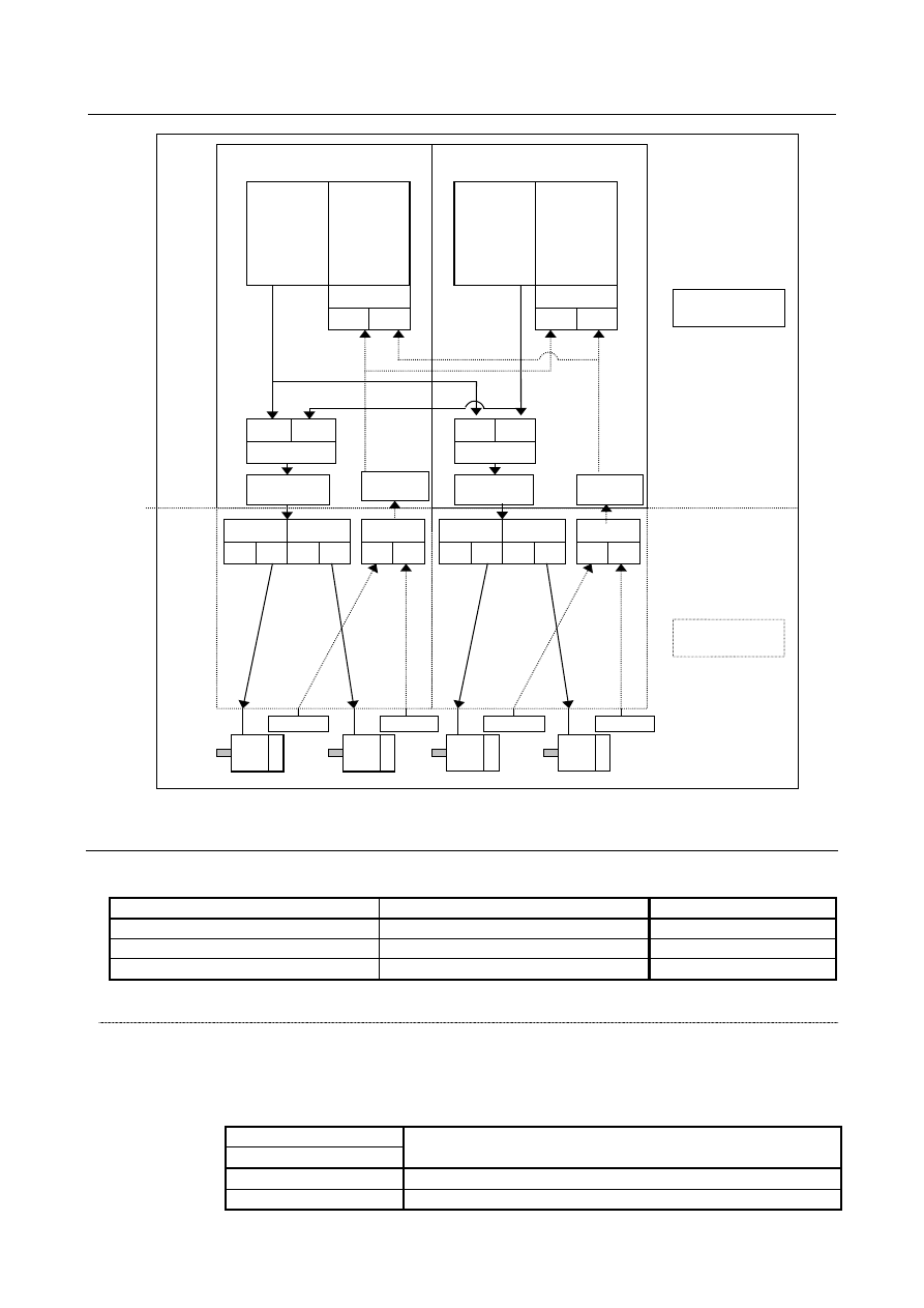
Fig. 8.11 (c) Configuration in which four spindles belonging to paths 1 and 2 are shared between the two 

paths (Path spindle control (signal type B) + multi-spindle control) 


Signal 

There are three signal types, which are selected with appropriate parameter settings. 

Bit 2 (MPM) of parameter No. 3703 

Bit 0 (2P2) of parameter No. 3703 

Signal type 

Signal type A 

Signal type B 

0/1 

Signal type C 


  - 

Signal type A 

Path spindle command selection signal SLSPA <G0063.2> 

  [Classification]  Input signal 
 

[Function]  This signal specifies the path of the program commands to be effective to the spindles 

belonging to path 1. 


[Operation]   

Signal input 

Program command to be effective to the spindle belonging to 

path m (= n + 1) 

SLSPA<G0063.2> 

Spindle command of path 1 

Spindle command of path 2 

B-64693EN-1/01


8. MULTI-PATH CONTROL


- 1387 - 


Path spindle feedback selection signal SLPCA<G0064.2>,SLPCB<G0064.3> 


[Function]  You need not control the path spindle feedback selection signal because the spindle 

feedback signal of path 1 is always effective to paths 1 and 2. 


Path spindle command confirmation signal COSP <F0064.5> 

  [Classification]  Output signal 
 

[Function]  This signal notifies which path the spindle command last specified came from. 


[Output cond.]  This signal becomes 1 under the following condition: 

A spindle command is issued from path 2. 

This signal becomes 0 under the following condition: 

A spindle command is issued from path 1, or no spindle command is issued from 
either path. 

In the state in which spindle commands for both paths 1 and 2 are effective to the spindles 
belonging to path 1, this signal allows you to determine which path the spindle command 
last specified came from. 


NOTE 

Spindle commands refer to S code commands, maximum speed 
command (G50S), M03/M04/M05, and commands for the constant 
surface speed control (G96 and G97). 


Spindle command

for path 1

Path 1

Spindle PC for
path 1

Spindle 1

Spindle
command

Spindle
feedback

Path 2

Spindle
command

Spindle
feedback

  SLSPA #1

   0

   1


Fig. 8.11 (d) Configuration in which the spindle of path 1 is shared by 2 paths 


8. MULTI-PATH CONTROL


B-64693EN-1/01


- 1388 - 

  - 

Signal type B 

Path spindle command selection signal SLSPA<G0063.2>,SLSPB<G0063.3> 

  [Classification]  Input signal 
 

[Function]  This signal specifies the path of the program commands to be effective to the spindles 

belonging to paths 1 and 2. 


[Operation]   

Signal input 

Program command to be effective to the spindle belonging to 

path 1 

SLSPA<G0063.2> 

Spindle command of path 1 

Spindle command of path 2 


Signal input 

Program command to be effective to the spindle belonging to 

path 2 

SLSPB<G0063.3> 

Spindle command of path 2 

Spindle command of path 1 


Path spindle feedback selection signal SLPCA<G0064.2>,SLPCB<G0064.3> 

  [Classification]  Input signal 
   

[Function]  In paths 1 and 2, this signal specifies the path to which the spindle to which position 

coder feedback pulses are to be effective belongs. 


  [Operation]   

Signal input 

In path 1, the path to which the spindle to which position coder 

feedback pulses are to be effective belongs 

SLPCA<G0064.2> 

Spindle PC of path 1 

Spindle PC of path 2 


Signal input 

In path 2, the path to which the spindle to which position coder 

feedback pulses are to be effective belongs 

SLPCB<G0064.3> 

Spindle PC of path 2 

Spindle PC of path 1 


Path spindle command confirmation signal COSP<F0064.5> 

  [Classification]  Output signal 
 

[Function]  This signal notifies which path the spindle command last specified came from. 


[Output cond.]  This signal becomes 1 under the following condition: 

A spindle command is issued from path 2. 

This signal becomes 0 under the following condition: 

A spindle command is issued from path 1, or no spindle command is issued from 
either path. 

In the state in which spindle commands for both paths 1 and 2 are effective to the spindles 
belonging to path 1, this signal allows you to determine which path the spindle command 
last specified came from. 


NOTE 

Spindle commands refer to S code commands, maximum speed 
command (G50S), M03/M04/M05, and commands for the constant 
surface speed control (G96 and G97). 


B-64693EN-1/01


8. MULTI-PATH CONTROL


- 1389 - 

1st spindle (path 2)

Spindle command

for path 1

Path 1

Spindle PC for
path 1

1st spindle (path 1)

Spindle
command

Spindle
feedback

Path 2

Spindle
command

Spindle
feedback

Spindle PC for
path 2

   0

   1

  SLSPA #1

  SLPCA #1

   0

   1

   1

   0

  SLSPB #1

Spindle command

for path 2

  SLPCB #1

   1

   0


Fig. 8.11 (e) Configuration in which the spindles in paths 1 and 2 are shared by 2 paths 

 
Signal address 


#7 

#6 

#5 

#4 

#3 

#2 

#1 

#0 

Gn063 


SLSPB 

SLSPA 


Gn064 


SLPCB 

SLPCA 


#7 

#6 

#5 

#4 

#3 

#2 

#1 

#0 

Fn064 


COSP 


Parameter 


#7 

#6 

#5 

#4 

#3 

#2 

#1 

#0 

3702 


EMS 


[Input type]  Parameter input 


[Data type]  Bit path 


#1  EMS

  The multi-spindle control is: 

0: 

Used. 

1: 

Not used.   


NOTE 

1  Set this parameter for a path that does not require multi-spindle 

control in a 2-path control system. 

2  To use this parameter requires enabling multi-spindle control 

(setting bit 3 (MSP) of parameter No. 8133). 

8. MULTI-PATH CONTROL


B-64693EN-1/01


- 1390 - 


#7 

#6 

#5 

#4 

#3 

#2 

#1 

#0 

3703 


MPP 

MPM 


2P2 


[Input type]  Parameter input 


[Data type]  Bit 


NOTE 

When at least one of these parameters is set, the power must be 
turned off before operation is continued. 


#0  2P2

  When a multi-path system is used, inter-path spindle control allows: 

0: 

Configuration where the spindle that belongs to one path only is shared between 
path 1 and path 2. 

1: 

Configuration where the spindles that belong to path 1 and 2 are shared between the 
two paths.   


#3  MPP

  In multi-spindle control, a spindle selection using a programmed command instead of 

using Spindle selection signals (SWS1 to SWS4<G027.0 to 2, G026.3>) is: 
0: 

Not made. 

1: 

Made. 


NOTE 

When this parameter is set to 1, set parameter No. 3781 at the same 
time. 


#7 

#6 

#5 

#4 

#3 

#2 

#1 

#0 

3706 


PCS 


[Input type]  Parameter input 


[Data type]  Bit path 


#3  PCS

  When a multi-path system is used, and multi-spindle control is enabled with each path, as 

the position coder signals (PC2SLC<Gn028.7>, PC3SLC<Gn026.0>, 
PC4SLC<Gn026.1>) for selecting the position coder of a spindle among the multiple 
spindles that belong to a path selected by the inter-path spindle feedback selection 
signals: 
0: 

The signals of the path selected by the inter-path spindle feedback selection signal 
are used. 

1: 

The signals of the local path are used. 

 
Suppose that path x is selected by the inter-path spindle feedback selection signals 
(SLPCA<Gn064.2>, SLPCB<Gn064.3>, SLPCC<Gn403.4>, SLPCD<Gn403.5>). Then, 
the following position coder is selected in path x by the position coder selection signals: 
n = m(path number)-1 
y = x(path number selected by the spindle feedback selection signals)-1 
 

When bit 3 (PCS) of parameter No. 3706 is set to 0 

Position coder 

selected in 

path m 

Selected path 

Position coder selection signals 

(path x) 

Selecting path 

Position coder selection signals 

(path m) 

PC2SLC 

<Gy028.7> 

PC3SLC 

<Gy026.0> 

PC4SLC 

<Gy026.1> 

PC2SLC 

<Gn028.7> 

PC3SLC 

<Gn026.0> 

PC4SLC 

<Gn026.1> 

PC1 of path x 

PC2 of path x 

PC3 of path x 

B-64693EN-1/01


8. MULTI-PATH CONTROL


- 1391 - 

Position coder 

selected in 

path m 

Selected path 

Position coder selection signals 

(path x) 

Selecting path 

Position coder selection signals 

(path m) 

PC2SLC 

<Gy028.7> 

PC3SLC 

<Gy026.0> 

PC4SLC 

<Gy026.1> 

PC2SLC 

<Gn028.7> 

PC3SLC 

<Gn026.0> 

PC4SLC 

<Gn026.1> 

PC4 of path x 


When bit 3 (PCS) of parameter No. 3706 is set to 1 

Position coder 

selected in 

path m 

Selected path 

Position coder selection signals 

(path x) 

Selecting path 

Position coder selection signals 

(path m) 

PC2SLC 

<Gy028.7> 

PC3SLC 

<Gy026.0> 

PC4SLC 

<Gy026.1> 

PC2SLC 

<Gn028.7> 

PC3SLC 

<Gn026.0> 

PC4SLC 

<Gn026.1> 

PC1 of path x 

PC2 of path x 

PC3 of path x 

PC4 of path x 


3781 


P code for selecting the spindle in multi-spindle control 


[Input type]  Parameter input 


[Data type]  Word spindle 

[Valid data range]  0 to 32767 

If bit 3 (MPP) of parameter No. 3703 is set to 1, set the P code to select each spindle 
under multi-spindle control. Specify the P code in a block containing the S command. 


[Example]  If the P code value for selecting the second spindle is set to 3, 

S1000 P3; 
causes the second spindle to rotate at S1000. 
 

NOTE 

1  This parameter is valid if bit 3 (MPP) of parameter No. 3703 is set 

to 1. 

2  If this parameter is set to 0, the corresponding spindle cannot be 

selected by a P code. 

3  Under multi-path control, the P code specified here is valid for each 

path. 
For instance, if the P code to select the first spindle of path 2 is set 
to 21, specifying S1000 P21; in path 1 causes the first spindle of 
path 2 to be rotated at S1000. 

4  Identical P code values cannot be used for different spindles. 

(Identical P code values cannot be used even if the paths are 
different.) 

5  When this parameter is used (when bit 3 (MPP) of parameter No. 

3703 is set to 1), the spindle command selection signal is invalid. 

6  To use this parameter, enable multi-spindle control (bit 3 (MSP) of 

parameter No. 8133 is 1). 


8. MULTI-PATH CONTROL


B-64693EN-1/01


- 1392 - 


#7 

#6 

#5 

#4 

#3 

#2 

#1 

#0 

8133 


MSP 


NOTE 

When this parameter is set, the power must be turned off before 
operation is continued. 


[Input type]  Parameter input 


[Data type]  Bit 


#3  MSP

  Multi-spindle is 

0: 

Not Used. 

1: 

Used. 


Alarm and message 

Number 

Message 

Description 

PS5305 

ILLEGAL SPINDLE NUMBER 

In a spindle select function by address P for a multiple spindle 
control, 
1)  Address P is not specified. 
2)  Parameter No. 3781 is not specified to the spindle to be 

selected. 

3)  An illegal G code which cannot be commanded with an 

S_P_; command is specified. 

4)  The multi spindle cannot be used because the bit 1 (EMS) 

of parameter No. 3702 is 1. 

5)  The spindle amplifier number of each spindle is not set in 

parameter No. 3717. 

6)  A prohibited command for a spindle was issued 

(parameter No. 11090). 

7)  An invalid value is set in parameter No. 11090. 


Note 

NOTE 

Signals used to operate the spindle control unit are not influenced by path 
spindle command selection signals; process them with a PMC Ladder program, 
if required. 
(Example: SFRA<G0070.5> is always a forward rotation command to the first 
serial spindle control amplifier of path 1.) 


Reference item 

Manual name 

Item name 

OPERATOR’S MANUAL (B-64694EN) 

SPINDLE CONTROL BETWEEN EACH PATH 


B-64693EN-1/01


8. MULTI-PATH CONTROL


- 1393 - 

8.12 

MEMORY COMMON TO PATHS   

Overview 

In a multipath system, this function enables data within the specified range to be accessed as data 
common to all paths. The data includes tool compensation memory and custom macro common variables. 
 

Explanation 

  - 

Tool compensation memory 

Part or all of tool compensation memory for individual paths can be used as common data by setting 
parameter No. 5029. 


Tool 
compensation 
number 20 

Tool 
compensation 
number 1 

50 tool 

compen-

sation 

values 

30 tool 

compen-

sation 

values 

Lathe system tool 

compensation for path 2 

No.5029=20 

Lathe system tool 

compensation for path 1 


Fig. 8.12 (a) 


NOTE 

1  Set a value less than the number of tool compensation values for each path for 

parameter No. 5029. 

2  If the value set for parameter No. 5029 is greater than the number of tool 

compensation values for each path, the minimum number of tool compensation 
values for individual paths is assumed. 


  - 

Custom macro common variables 

All or part of custom macro common variables #100 to #149 (or #199) and #500 to #599 (or #999) can be 
used as common data by setting parameters Nos. 6036 (#100 to #149 (, #199, or #499)) and 6037 (#500 
to #599 (or #999)). 

50 macro
variables

50 macro
variables

Macro variable number 119

Macro variable number 100

Macro variables

for path 1

No.6036=20

Macro variables

for path 2


Fig. 8.12 (b) 


NOTE 

If the value of parameter No. 6036 or 6037 exceeds the maximum number of 
macro common variables, the maximum number of macro common variables is 
assumed. 


Content      ..     177      178      179      180     ..