FANUC Series 0i-MODEL F Plus. CONNECTION MANUAL (FUNCTION) - page 166
 

  Index      Manuals     FANUC Series 0i-MODEL F Plus. CONNECTION MANUAL (FUNCTION) B-64693EN-1/01


Search            copyright infringement  


Content      ..     164      165      166      167     ..


FANUC Series 0i-MODEL F Plus. CONNECTION MANUAL (FUNCTION) - page 166


8. MULTI-PATH CONTROL


B-64693EN-1/01


- 1282 - 

Address P to be specified in the same block as that containing a waiting M code can be set in either of 
two ways: 

When the bit 1 (MWP) of parameter No. 8103 is set to 0 : 
Waiting with a binary value specification 

When the bit 1 (MWP) of parameter No. 8103 is set to 1 : 
Waiting with a path number combination specification 


  - 

Waiting specified with binary values 

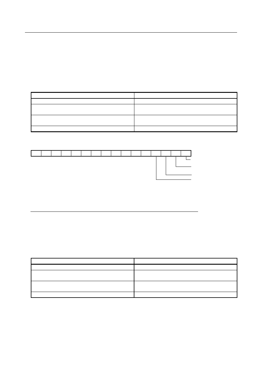
When bit 1 (MWP) of parameter No. 8103 is set to 0, the value specified at address P is assumed to be 
obtained using binary values. The following table lists the path numbers and corresponding binary values. 

Path number 

Binary value (decimal number) 

2 or 

Loader path 1(1 control path) 

Loader path 1 (2 control paths) or 

Loader path 2(1 control path) 

Loader path 2 (2 control paths) 


The bit position of each path in binary representation is shown below. 

15 

14 

13 

12 

11 

10 


Path 1( 2

= 1 ) 


Path 2 or 
Loader path( 2

= 2 ) 


Loader path( 2

= 4 ) 


Loader path( 2

= 8 ) 

 
To make all of paths 1, 2, and 3 wait for one another, the P value is obtained as follows: 
Binary value of path 1 

1 (0000 0000 0000 0001) 

Binary value of path 2 

2 (0000 0000 0000 0010) 

Binary value of path 3 

4 (0000 0000 0000 0100) 


Sum  


7 (0000 0000 0000 0111) 

 
All of the three paths can be made to wait for one another by specifying P7 together with an M code for 
waiting. 
 

  - 

Waiting specified with a combination of path numbers 

When bit 1 (MWP) of parameter No. 8103 is set to 1, the value specified at address P is assumed to be a 
combination of path numbers. The following table lists the path numbers and corresponding values. 

Path number 

Value (decimal number) 

2 or 

Loader path 1(1 control path) 

Loader path 1 (2 control paths) or 

Loader path 2(1 control path) 

Loader path 2 (2 control paths) 

 
To make all of paths 1, 2, and 3 wait for one another, the P value is a number consisting of 1, 2, and 3. 
Example) P123 
There are no restrictions on the order in which the numeric characters are specified, the following six 
possible values can be specified: 

P123, P132, P213, P231, P312, P321 

Path numbers specified in combination in different orders for different paths are effective as long as the 
numbers of the relevant paths are specified. 

B-64693EN-1/01


8. MULTI-PATH CONTROL


- 1283 - 

Example) 
 

The following are treated as the same P value and these paths can be made to wait for one another: 


M200P123 for path 1, M200P231 for path 2, and M200P321 for path 3 


Program example 

  - 

When the value specified at P is obtained using binary values 

Assume that the no-wait signal NOWT <G0063.1> for path 2 (NMWT<G1063.7> for a system with three 
or more paths) is set to "1"  and M101 to M103 (parameter No. 8110 = 101 and parameter No. 8111 = 
103) are set as M codes for waiting. In this case, programs O100, O200, and O300 for individual paths 
are executed as follows: 
 

O0300;

G50 X    Z    ;

G00 X    Z    T0303;

M102 P7;  ................. <2>

O0100;

G50 X    Z    ;

G00 X    Z    T0101;

M03 S1000;

.

.

M101 P3; .................. <1>

G01 X    Z    F    ;

.

.

M102 P7; .................. <2>

M103 P7; .................. <3>

O0200;

G50 X    Z    ;

G00 X    Z    T0202;

M03 S2000;

M101 P3; .................. <1>

G01 X    Z    F    ;

.

.

M102 P7; .................. <2>

M103 P7; .................. <3>

.

.

.

.

.

.

.
.
.

G00 X    Z    ;

.

.

M103 P7; .................. <3>

G00 X    Z    ;

.

G01 X    Z    F    ;

.
.

<<Waiting (M102)>>

<<Waiting (M103)>>

Path 1

Path 2

Path 3


<1>  M101 P3; (making paths 1 and 2 wait for each other) 
 

When the no-wait signal for path 2 is set to "0", paths 1 and 2 wait for each other. Because the signal 
is set to "1", however, paths 1 and 2 ignore the M code for waiting and immediately execute the next 
block. 

<2>  M102 P7; (making paths 1, 2, and 3 wait for one another) 
 

In this example, path 3 waits for processing on paths 1 and  2 to terminate. Because the no-wait 
signal for path 2 is set to "1", however, path 3 assumes that waiting is completed when processing on 
path 1 terminates, and executes the next block. 

<3>  M103 P7; (making paths 1, 2, and 3 wait for one another) 
 

In this example, paths 1 and 2 wait for processing on path 3 to terminate. Because the no-wait signal 
for path 2 is set to "1", however, path 2 does not wait for processing on path 3 to terminate and 
executes the next block, but path 1 waits for path 3. 


  - 

When the value specified at P is obtained using path numbers in combination 

Assume that the no-wait <G0063.1> signal for path 2 (NMWT<G1063.7> for a system with three or more 
paths) is set to "1" and M101 to M103 (parameter No. 8110 = 101 and parameter No. 8111 = 103) are set 
as M codes for waiting. In this case, programs O100, O200, and O300 for individual paths are executed as 
follows: 

8. MULTI-PATH CONTROL


B-64693EN-1/01


- 1284 - 

O0300;

G50 X    Z    ;

G00 X    Z    T0303;

M102 P123;  ............. <2>

O0100;

G50 X    Z    ;

G00 X    Z    T0101;

M03 S1000;

.

.

M101 P12; ................ <1>

G01 X    Z    F    ;

.

.

M102 P123; .............. <2>

M103 P123; .............. <3>

O0200;

G50 X    Z    ;

G00 X    Z    T0202;

M03 S2000;

M101 P12; ................ <1>

G01 X    Z    F    ;

.

.

M102 P123; .............. <2>

M103 P123; .............. <3>

.

.

.

.

.

.

.
.
.

G00 X    Z    ;

.

.

M103 P123; .............. <3>

G00 X    Z    ;

.

G01 X    Z    F    ;

.
.

<<Waiting (M102)>>

<<Waiting (M103)>>

Path 1

Path 2

Path 3


<1>  M101 P12; (making paths 1 and 2 wait for each other) 
 

When the no-wait signal for path 2 is set to "0", paths 1 and 2 wait for each other. Because the signal 
is set to "1", however, paths 1 and 2 ignore the M code for waiting and immediately execute the next 
block. 

<2>  M102 P123; (making paths 1, 2, and 3 wait for one another) 
 

In this example, path 3 waits for processing on paths 1 and 2 to terminate. Because the no-wait 
signal for path 2 is set to "1", however, path 3 assumes that waiting is completed when processing on 
path 1 terminates, and executes the next block. 

<3>  M103 P123; (making paths 1, 2, and 3 wait for one another) 
 

In this example, paths 1 and 2 wait for processing on path 3 to terminate. Because the no-wait signal 
for path 2 is set to "1", however, path 2 does not wait for processing on path 3 to terminate and 
executes the next block, but path 1 waits for path 3. 


Signal 

You can invalidate waiting by using the no-wait signal. 
The waiting M code of a path for which the no-wait signal is "1" is ignored by other paths, thereby 
invalidating waiting. You use this signal if you are to perform automatic operation with a program 
containing a waiting M code, but you want to keep a certain path stopped while performing automatic 
operation in the other paths. For the path that you want to keep stopped, set the no-wait signal to "1". 
 

No-wait signal 

NOWT<G0063.1>(for path common signal interface) 


NMWT<Gn063.7>(for path individual signal interface) 

  [Classification]  Input signal 
 

[Function]  Specifies whether to synchronize the paths by the waiting M code. 


[Operation]  When this signal turns to "1" the paths are not synchronized by the M code. The M code 

for waiting specified in a machining program is ignored. 
When this signal turns to "0", the paths are synchronized by the M code. When the M 
code for waiting is specified for one path, the CNC waits for the corresponding M code of 
another path to be issued, then starts executing the next block.   


B-64693EN-1/01


8. MULTI-PATH CONTROL


- 1285 - 

Waiting signal 

WATO<F0063.6>(for path common signal interface) 


WATO<Fn063.6>(for path individual signal interface) 

  [Classification]  Output signal 
 

[Function]  Indicates that the M code is waiting for a path. 


[Output cond.]  These signals are "1" as long as: 

One path is waiting for another path. That is, the signal stays "1" for the period from 
when the M code for waiting is issued to one path to when the corresponding M 
code is issued to another path. 

This signal is "0" as long as: 

Neither of the paths are waiting for the other. 


NOTE 


When the path common signal interface (bit 0 (MWT) of parameter 
No. 8103 = 1) is used, F0063.6=1 results even if path 2 is placed in 
the wait state. 


So, when the wait state needs to be checked with each path, use 
the path individual signal interface (bit 0 (MWT) of parameter No. 
8103 = 0). 


Signal address 

  - 

For path common signal interface 


#7 

#6 

#5 

#4 

#3 

#2 

#1 

#0 

G0063 


NOWT 


#7 

#6 

#5 

#4 

#3 

#2 

#1 

#0 

F0063 


WATO 


  - 

For path individual signal interface 


#7 

#6 

#5 

#4 

#3 

#2 

#1 

#0 

Gn063 


NMWT 


#7 

#6 

#5 

#4 

#3 

#2 

#1 

#0 

Fn063 


WATO 


Parameter 


#7 

#6 

#5 

#4 

#3 

#2 

#1 

#0 

8103 


MWP 

MWT 


[Input type]  Parameter input 


[Data type]  Bit 


NOTE 


When at least one of these parameters is set, the power must be 
turned off before operation is continued. 


#0  MWT

  As the signal interface for the waiting M code: 

0: 

The path individual signal interface is used. 

1: 

The path common signal interface is used. 

This parameter can be selected only when 2-path control is used. 


#1  MWP

  To specify a P command for the waiting M code/balance cut: 

0: 

A binary value is used as conventionally done. 

1: 

A path number combination is used. 


8. MULTI-PATH CONTROL


B-64693EN-1/01


- 1286 - 

8110 


Waiting M code range (minimum value) 


8111 


Waiting M code range (maximum value) 


[Input type]  Parameter input 


[Data type]  2-word 

[Valid data range]  0 ,100to99999999 

A range of M code values can be set by specifying a minimum waiting M code value 
(parameter No. 8110) and a maximum waiting M code value (parameter No. 8111). 
(parameter No. 8110) 

 (waiting M code) 

 (parameter No. 8111) 

Set 0 in these parameters when the waiting M code is not used. 
 

Alarm and message 

Number 

Message 

Description 

PS0160 

MISMATCH WAITING 
M-CODE 

<1>  When different M codes are specified for path 1 and path 2 as 

waiting M codes without a P command. 

<2>  When the waiting M codes are not identical even though the P 

commands are identical 

<3>  When the waiting M codes are identical and the P commands are 

not identical (This occurs when a P command is specified with 
binary value.) 

<4>  When the number lists in the P commands contain a different 

number even though the waiting M codes are identical (This occurs 
when a P command is specified by combining path numbers.) 

<5>  When a waiting M code without a P command (2-path waiting) and a 

waiting M code with a P command (3-or-more-path waiting) were 
specified at the same time 

<6>  When a waiting M code without a P command was specified for 3 or 

more paths. 

PS0161 

ILLEGAL P OF WAITING 
M-CODE 

<1>  When address P is negative 
<2>  When a P value inappropriate for the system configuration was 

specified 

<3>  When a waiting M code without a P command (2-path waiting) was 

specified in the system having 3 or more paths. 

 
An alarm occurs in all the paths in which an alarm-related waiting M code has been executed, bringing 
them into a single block stop and placing them in the automatic operation stop state. 
At this time, the paths other than the alarm-related ones are stopped immediately, entering the automatic 
operation idle state. 
 

Caution 

  CAUTION 

1  Be sure to specify a waiting M code in an independent block. 
2  Unlike other M codes, waiting M codes are not output to PMCs. 
3  If you want to independently operate one path only, you need not delete that 

waiting M code. Using the no-wait signal (NOWT for a 2-path system and NMWT 
for a 3-path system), you can invalidate the waiting M code specified in the 
machining program. For details, refer to the manual issued by the machine tool 
builder. 

4  To use a waiting M code in mode for multiple M commands in a single block, the 

M code must be specified as the first M code. 


B-64693EN-1/01


8. MULTI-PATH CONTROL


- 1287 - 

Reference item 

Manual name 

Item name 

OPERATOR’S MANUAL (B-64694EN) 

WAITING FUNCTION FOR PATHS 


8.3 

WAITING M CODES OF HIGH-SPEED TYPE 

Overview 

Waiting M codes of high-speed type are useful function to reduce the cycle time of a program operation. 
 

Specification 

In order to use Waiting M codes of high-speed type, it is necessary to set the range of the  M codes to 
parameters Nos.8114 and 8115. 
The usage of these type M codes  is similar to  normal  waiting M codes. For instance, the ways to set  a 
path by address P and to use a no-wait signal or so on are the same. 
 

Format 

m

 (P 

p)

 ; 

:  Number of an M code for waiting 

:  (1) In the binary value specification mode, specify the sum of the binary values 

corresponding to the numbers of paths which are to wait for one another. 


  (2) In the path number specification mode, specify the numbers of all paths that 

are to wait for one another in combination. 


NOTE 

1  Specify a waiting M code only in a block.   
2  The irrelevant command, which is specified with a waiting M code in a block, is 

ignored. 


Detail 

Specifying the path by address P 

The way to specify the path by address P is the same as normal waiting M codes. 
 

Waiting signal 

Waiting signal WATO<F0063.6> (for path common signal interface) and WATO<Fn063.6> (for path 
individual signal interface) are output like normal waiting M codes. 
 

No-wait signal 

No-wait signal NOWT<G0063.1>  (for path common signal interface)  and  NMWT<Gn063.7>  (for path 
individual signal interface) are effective like normal waiting M codes. 
 

Waiting M codes of high-speed type invalid signal 

Waiting M codes of high-speed type are treated as normal waiting M codes when waiting M codes of 
high-speed type invalid signal NHSW<G0579.6> is set to "1". 
 

Limitation 

Display of the currently executing program 

Instead of the block of waiting M code,  the block before waiting M code is displayed as the currently 
executing program during waiting of high-speed type. 
 

8. MULTI-PATH CONTROL


B-64693EN-1/01


- 1288 - 

Function code signal and strobe signal 

As for waiting M code of high-speed type, the function code signal and strobe signal are not output. 
 

Modal display 

Waiting M codes of high-speed type are not displayed as the information of M code modal. 
 

Condition to treat waiting M codes of high-speed type as normal waiting M codes 

When  one  of  the following conditions  is  satisfied, waiting M codes of high-speed type are treated as 
normal waiting M codes. 
 

Waiting M codes of high-speed type invalid signal is set to "1". 

The single-block operation is enabled. 

Waiting M codes of high-speed type are specified in the same block as the program number. 

In manual handle retrace function, the checking mode synchronizing an operation with a manual 
handle pulse is selected. 

Animation or path drawing of dynamic graphic display is operated. 


NOTE 

1  Waiting between waiting M codes of high-speed type and waiting M codes of 

high-speed type treated as normal waiting M codes cannot be executed when 
setting bit 7 (HMA) of parameter No.11279 to 0. In this case, alarm (PS0160) 
“MISMATCH WAITING M-CODE” occurs. 
Example) 

When either path 1 or path 2 is under the single block operation and waiting 
by "waiting M code of high-speed type" is executed between path 1 and 
path2, alarm (PS0160) occurs. 

2  Waiting between waiting M codes of high-speed type and waiting M codes of 

high-speed type treated as normal waiting M codes can be executed when 
setting bit 7 (HMA) of parameter No.11279 to 1. And, waiting M codes of 
high-speed type can be specified during Relation of cutter compensation by 
setting bit 7 (HMA) of parameter No.11279 to 1. In this case, waiting M codes of 
high-speed type are not work at a high-speed, waiting M codes of high-speed 
type are treated as normal waiting M codes, and the processing time of waiting 
M codes of high-speed type is equal with normal waiting M codes. 


Auxiliary function output in moving axis 

Waiting is not executed even if waiting M code of high-speed type is specified, when Auxiliary function 
output in moving axis (G50.9) is given in the same  block.  In this case, M code is treated as a normal 
auxiliary function. 
 

Manual handle retrace function 

In Manual handle retrace function, a backward movement cannot be executed while the block of waiting 
M codes of high-speed type  is executing.  The backward movement ends  when an operation enters  the 
next block of waiting M code of high-speed type during the backward movement.  And  ‘RVED’  is 
displayed. 
However, in the checking mode synchronizing with a manual handle pulse, the backward movement can 
be executed when  waiting M code of high-speed type was executed once during  forward movement, 
because the M code is treated as a normal M code in this case. 
 

B-64693EN-1/01


8. MULTI-PATH CONTROL


- 1289 - 

Retrace 

The backward movement cannot be executed by Retrace function in the block of waiting M codes of 
high-speed type. The backward movement ends when the next block of waiting M code of high-speed 
type just starts executing during the backward movement. And ‘RVED’ is displayed. 
 

Waiting function by specifying start point 

Waiting M codes of high-speed type cannot act  as  a  waiting function by specifying start point.  Alarm 
(PS0160) occurs when such a command is specified. Use normal waiting M codes to use waiting function 
by specifying start point. 
 

Relation of cutter compensation 

Waiting M codes of high-speed type cannot be specified  during the following cutter compensation 
functions. Alarm (PS0160) occurs when such a command is specified. Set the bit 7 (HMA) of parameter 
No.11279 to 1, or use normal waiting M codes during the following cutter compensation functions. 
- Cutter compensation and tool nose radius compensation 


NOTE 


Waiting M codes of high-speed type cannot be specified just after the cancel 
command of cutter compensation, tool nose radius compensation. Moreover, 
waiting M codes of high-speed type cannot be specified while the vector of cutter 
compensation is being held. 


Multiple repetitive canned cycle 

Waiting M codes of high-speed type cannot be specified during Multiple repetitive canned cycle G70 to 
G73. Alarm (PS0160) occurs when such a command is specified. Use normal waiting M codes during 
Multiple repetitive canned cycle G70 to G73. 
 

Chamfering and corner R, Optional chamfering and corner R and Direct drawing 
dimension programming 

In the condition to treat waiting M codes of high-speed type as normal waiting M codes, alarm (PS0051) 
“MISSING MOVE AFTER CNR/CHF” occurs when waiting M codes of high-speed type are specified 
during Chamfering and corner R or Optional chamfering and corner R. And alarm (PS0312) “ILLEGAL 
COMMAND IN DIRECT DRAWING DIMENSIONS PROGRAMMING” occurs when waiting M codes 
of high-speed type are specified during Direct drawing dimension programming. 
 

Quick program restart 

When the program is interrupted by reset or etc. while executing waiting of high-speed type, the previous 
block of waiting M codes is regarded as the last restart point, instead of the block of waiting M codes. 
 

Output to the PMC 

Waiting M codes are not output to the PMC unlike the other M codes. 
 

Occurring alarm while waiting 

The state of cycle start lamp signal STL<Fn000.5> is as follows when an alarm occurs while waiting. 


Cycle start lamp signal STL<Fn000.5> 

When alarms PS, SR or IO occurs. 

When other alarms occurs. 

Waiting M codes of normal 

STL = 1 

STL = 0 

Waiting M codes of high-speed type 

STL = 0 

STL = 0 


Content      ..     164      165      166      167     ..