FANUC Series 0i-MODEL F Plus. CONNECTION MANUAL (FUNCTION) - page 160
 

  Index      Manuals     FANUC Series 0i-MODEL F Plus. CONNECTION MANUAL (FUNCTION) B-64693EN-1/01


Search            copyright infringement  


Content      ..     158      159      160      161     ..


FANUC Series 0i-MODEL F Plus. CONNECTION MANUAL (FUNCTION) - page 160


B-64693EN-1/01


- 1234 - 

7. FEEDRATE CONTROL/ACCELERATION AND 

DECELERATION CONTROL 

Go back to the measurement window and after setting S command and upper limit of motor speed, click 
“Start”. Please set higher value than the maximum rigid tapping speed in S command box, if you can. 


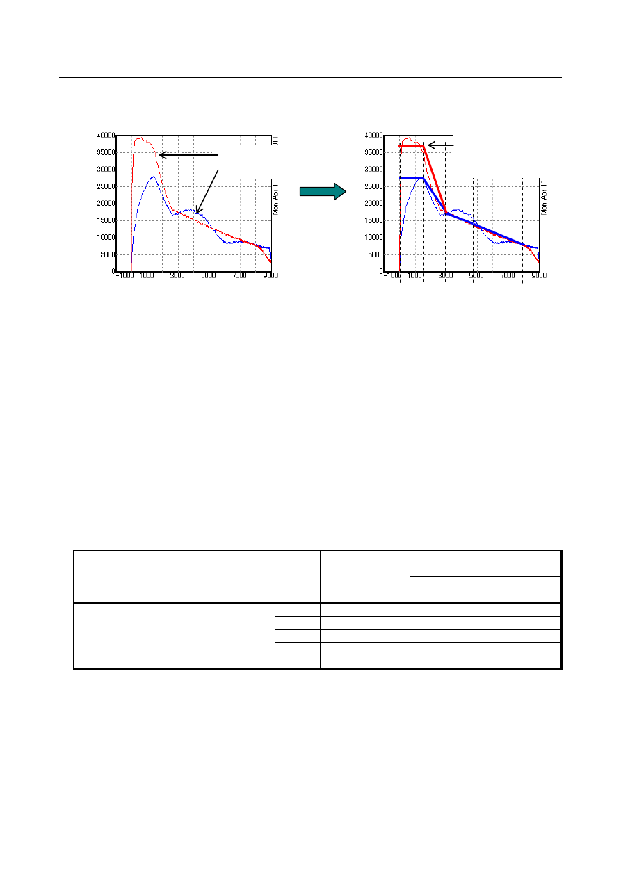
Please estimate the initial setting values from the measurement result. Please draw approximate line 
through each setting point (P0-P4) to determine the acceleration character during acc./dec.. The  above 
data shows the character in acc./dec. with maximum torque. So available torque in rigid tapping will be 
less than this character. Please set the initial value for optimum acc./dec. for rigid tapping as 70% or so of 
approximate line. 
 

Example)The  maximum acceleration  (parameter No.11421)  can be seen at 0-1500min

-1

  in 

deceleration. It’s value is 

]

sec

/

[

441

7

.

0

[sec]

60

sec]

/

)[min

min

1500

~

0

(

37800

2

1

1

rev

=

×

÷


The rest of acceleration settings should be set as the proportion of this value. 

 
Example)Parameter No.11441 is calculated from acceleration value (27600min

-1

/sec) at 0-1500min

-1


in acceleration as follows: 

[%]

73

100

sec]

/

[min

37800

/

sec]

/

[min

27600

1

1

=

×


Table 7.2.8 (c) Initial settings for optimum acc./dec. for rigid tapping 

Gear 

Maximum   

acceleration 

[rev/sec

2

Maximum   

spindle speed 

[min

-1

Acc. 

setting 

point 

Spindle speed 

(Ratio to max.   

speed [%]) 

Acc. setting 

  (Ration to max. acc. [%]) 

Forward / Reverse   

During acc. 

During dec. 

Gear 1 

No.11421=441 

No.5241=8000 

P0 

None(0%) 

No.11441=73 

No.11461=100 

P1 

No.11429=19 

No.11442=73 

No.11462=100 

P2 

No.11430=38 

No.11443=46 

No.11463=46 

P3 

No.11431=60 

No.11444=36 

No.11464=36 

P4 

None(100%) 

No.11445=20 

No.11465=20 


[min

-1

Acceleration during dec. 

Acceleration during acc. 

Draw approximate 

line for acceleration 

character curve 

[min

-1

/sec] 

We regard this level as 100%. 

Based on this level, please 

calculate the acceleration 

value in each point. 

P0   P1    P2    P3          P4 

B-64693EN-1/01


- 1235 - 

7. FEEDRATE CONTROL/ACCELERATION 

AND DECELERATION CONTROL 


Fig. 7.2.8 (g) Initial settings for optimum acc./dec. for rigid tapping 


Fig. 7.2.8 (h) Example of measurement result after initial setting of optimum acc./dec. for rigid tapping 


(2)Tune the parameters so that the spindle torque command reaches near 100% in 

all speed area 

Capture the data during the rigid tapping under initial setting of optimum acc./dec. for rigid tapping by 
using SERVO GUIDE. The data of spindle speed (SPSPD) and torque command (TCMD2(NOTE)) 
should be captured. After confirming the measurement result with initial setting, please tune the 
acceleration parameters so that the spindle torque command reaches near 100% in all speed area. When 
you tune them, please use the test program, which has the assumed maximum rigid tapping  speed, and 
start tuning from the high speed point (P4) first, and continue tuning the low speed points in order. 
 

NOTE 

TCMD2 shows the torque command rate, in which the maximum torque, 
considering torque limit value at each speed, is 100%. 
To capture this data, following SERVO GUIDE and spindle software is required.   

       SERVO GUIDE: Ver.8.10 or later 

   Spindle soft: 9DA0 series 14 edition or later 

If you can't use TCMD2, please use TCMD. However, TCMD does not consider   
torque limit value. Thus, TCMD might be saturated at a value which is lower 
than 100%. You can see whether torque command is saturated or not by 
watching the data of bit12 of “SFLG1”. Please watch them together, if you use 
TCMD. 


0

50

100

150

200

250

300

350

400

450

500

0

1000

2000

3000

4000

5000

6000

7000

8000

Spindle speed(min^-1)

A

ccel

er

at

io

n(r

ev

/s

ec^

2)

P0 

P1 

P2 

P3 

P4 

: Acceleration during dec. 

: Acceleration during acc. 

Spindle speed (2000min

-1

/div) 

Synchronous error (50pulse/div) 

Spindle torque command (50%/div)


600ms


We can tune the acceleration settings a little more, 

because there is a room to 100% in torque command. 


B-64693EN-1/01


- 1236 - 

7. FEEDRATE CONTROL/ACCELERATION AND 

DECELERATION CONTROL 

Table 7.2.8 (d) After tuning settings for optimum acc./dec. for rigid tapping 

Gear 

Maximum 

acceleration 

[rev/sec

2

Maximum 

spindle 

speed 

[min

-1

Acc. 

setting 

point 

Spindle speed 

(Ratio to max.   

speed [%]) 

Acc. setting 

(Ration to max. acc. [%]) 

Forward / Reverse   

During acc. 

During dec. 

Gear 1 

No.11421=441 

No.5241=8000 

P0 

None(0%) 

No.11442=73 

No.11462=100 

P1 

No.11429=19 

No.11442=73 

No.11462=100 

P2 

No.11430=38 

No.11443=52 

No.11463=60 

P3 

No.11431=60 

No.11444=47 

No.11464=55 

P4 

None(100%) 

No.11445=20 

No.11465=40 


Fig. 7.2.8 (i) After tuning settings for optimum acc./dec. for rigid tapping 


Fig. 7.2.8 (j) Example of measurement result after tuning of optimum acc./dec. for rigid tapping 

 
In the above example, the acceleration time and deceleration time are reduced as follows by applying 
optimum acc./dec. for rigid tapping. 


Function OFF 

Function ON 

Acceleration time 

976 ms 

720 ms 

Deceleration time 

976 ms 

588 ms 


Parameter 


#7 

#6 

#5 

#4 

#3 

#2 

#1 

#0 

11420 


RAU 


[Input type]  Parameter input 


[Data type]  Bit path 


0

50

100

150

200

250

300

350

400

450

500

0

1000

2000

3000

4000

5000

6000

7000

8000

Spindle speed(min^-1)

A

ccel

er

at

io

n(r

ev

/s

ec^

2)

P0 

P1 

P2 

P3 

P4 

: Acceleration during dec. 

: Acceleration during acc. 


Spindle speed (2000min

-1

/div) 

Synchronous error (50pulse/div) 

Spindle torque command (50%/div)


600ms


The motor torque is well   

utilized in all speed area.   

B-64693EN-1/01


- 1237 - 

7. FEEDRATE CONTROL/ACCELERATION 

AND DECELERATION CONTROL 


#0  RAU

  Optimum torque acceleration/deceleration function for rigid tapping is 

0: 

Disabled. 

1: 

Enabled. 


11421 


Maximum acceleration of the optimum acceleration/deceleration for rigid tapping (gear 1) 


11422 


Maximum acceleration of the optimum acceleration/deceleration for rigid tapping (gear 2) 


11423 


Maximum acceleration of the optimum acceleration/deceleration for rigid tapping (gear 3) 


11424 


Maximum acceleration of the optimum acceleration/deceleration for rigid tapping (gear 4) 


[Input type]  Parameter input 


[Data type]  2-word spindle 


[Unit of data]  rev/sec

2


[Valid data range]  0 to 10000.0 

These parameters set maximum accelerations. 
 

11425 


Acceleration change time of bell-shaped acceleration/deceleration in optimum 

acceleration/deceleration for rigid tapping (gear 1) 


11426 


Acceleration change time of bell-shaped acceleration/deceleration in optimum 

acceleration/deceleration for rigid tapping (gear 2) 


11427 


Acceleration change time of bell-shaped acceleration/deceleration in optimum 

acceleration/deceleration for rigid tapping (gear 3) 


11428 


Acceleration change time of bell-shaped acceleration/deceleration in optimum 

acceleration/deceleration for rigid tapping (gear 4) 


[Input type]  Parameter input 


[Data type]  Word spindle 


[Unit of data]  msec 


[Valid data range]  0 to 200 

These parameters 

set the acceleration change time of bell-shaped 

acceleration/deceleration in optimum acceleration/deceleration for rigid tapping (time 
taken for the change from the constant speed state (A) to the acceleration state (C) with 
the acceleration calculated from the optimum acceleration/deceleration for rigid tapping, 
i.e., the time indicated by (B) in the figure below). 


Speed (min

-1

Maximum acceleration that does not 

exceed the maximum permissible 

acceleration is automatically calculated. 

Acceleration change time 

(A) 

(B) 

(B) 

(B) 

(B) 

(A) 

(A) 

(C) 

(C) 


B-64693EN-1/01


- 1238 - 

7. FEEDRATE CONTROL/ACCELERATION AND 

DECELERATION CONTROL 

11429 


Spindle speed at P1 in optimum acceleration/deceleration for rigid taping (gear 1) 


11430 


Spindle speed at P2 in optimum acceleration/deceleration for rigid taping (gear 1) 


11431 


Spindle speed at P3 in optimum acceleration/deceleration for rigid taping (gear 1) 


11432 


Spindle speed at P1 in optimum acceleration/deceleration for rigid taping (gear 2) 


11433 


Spindle speed at P2 in optimum acceleration/deceleration for rigid taping (gear 2) 


11434 


Spindle speed at P3 in optimum acceleration/deceleration for rigid taping (gear 2) 


11435 


Spindle speed at P1 in optimum acceleration/deceleration for rigid taping (gear 3) 


11436 


Spindle speed at P2 in optimum acceleration/deceleration for rigid taping (gear 3) 


11437 


Spindle speed at P3 in optimum acceleration/deceleration for rigid taping (gear 3) 


11438 


Spindle speed at P1 in optimum acceleration/deceleration for rigid taping (gear 4) 


11439 


Spindle speed at P2 in optimum acceleration/deceleration for rigid taping (gear 4) 


11440 


Spindle speed at P3 in optimum acceleration/deceleration for rigid taping (gear 4) 


[Input type]  Parameter input 


[Data type]  Byte spindle 


[Unit of data]  % 


[Valid data range]  0 to 100 

These parameters set the spindle speeds at P1 to P3 of acceleration points P0 to P4 as 
ratios to the maximum spindle speed (parameters Nos. 5241 to 5244). The spindle speed 
at P0 is 0, while the spindle speed at P4 is the maximum spindle speed. Any acceleration 
setting points where 0 is set will be skipped. 


11441 


Permissible acceleration at P0 in optimum acceleration/deceleration for rigid tapping (gear 1) 


11442 


Permissible acceleration at P1 in optimum acceleration/deceleration for rigid tapping (gear 1) 


11443 


Permissible acceleration at P2 in optimum acceleration/deceleration for rigid tapping (gear 1) 


11444 


Permissible acceleration at P3 in optimum acceleration/deceleration for rigid tapping (gear 1) 


11445 


Permissible acceleration at P4 in optimum acceleration/deceleration for rigid tapping (gear 1) 


11446 


Permissible acceleration at P0 in optimum acceleration/deceleration for rigid tapping (gear 2) 


11447 


Permissible acceleration at P1 in optimum acceleration/deceleration for rigid tapping (gear 2) 


11448 


Permissible acceleration at P2 in optimum acceleration/deceleration for rigid tapping (gear 2) 


11449 


Permissible acceleration at P3 in optimum acceleration/deceleration for rigid tapping (gear 2) 


11450 


Permissible acceleration at P4 in optimum acceleration/deceleration for rigid tapping (gear 2) 


B-64693EN-1/01


- 1239 - 

7. FEEDRATE CONTROL/ACCELERATION 

AND DECELERATION CONTROL 

11451 


Permissible acceleration at P0 in optimum acceleration/deceleration for rigid tapping (gear 3) 


11452 


Permissible acceleration at P1 in optimum acceleration/deceleration for rigid tapping (gear 3) 


11453 


Permissible acceleration at P2 in optimum acceleration/deceleration for rigid tapping (gear 3) 


11454 


Permissible acceleration at P3 in optimum acceleration/deceleration for rigid tapping (gear 3) 


11455 


Permissible acceleration at P4 in optimum acceleration/deceleration for rigid tapping (gear 3) 


11456 


Permissible acceleration at P0 in optimum acceleration/deceleration for rigid tapping (gear 4) 


11457 


Permissible acceleration at P1 in optimum acceleration/deceleration for rigid tapping (gear 4) 


11458 


Permissible acceleration at P2 in optimum acceleration/deceleration for rigid tapping (gear 4) 


11459 


Permissible acceleration at P3 in optimum acceleration/deceleration for rigid tapping (gear 4) 


11460 


Permissible acceleration at P4 in optimum acceleration/deceleration for rigid tapping (gear 4) 


[Input type]  Parameter input 


[Data type]  Byte spindle 


[Unit of data]  % 


[Valid data range]  0 to 100 

These parameters set the permissible accelerations at acceleration setting points P0 to P4 
as ratios to the maximum acceleration (parameters Nos. 11421 to 11424). At any 
acceleration setting points where 0 is set, 100% is assumed. 


11461 


Permissible deceleration at P0 in optimum acceleration/deceleration for rigid tapping (gear 1) 


11462 


Permissible deceleration at P1 in optimum acceleration/deceleration for rigid tapping (gear 1) 


11463 


Permissible deceleration at P2 in optimum acceleration/deceleration for rigid tapping (gear 1) 


11464 


Permissible deceleration at P3 in optimum acceleration/deceleration for rigid tapping (gear 1) 


11465 


Permissible deceleration at P4 in optimum acceleration/deceleration for rigid tapping (gear 1) 


11466 


Permissible deceleration at P0 in optimum acceleration/deceleration for rigid tapping (gear 2) 


11467 


Permissible deceleration at P1 in optimum acceleration/deceleration for rigid tapping (gear 2) 


11468 


Permissible deceleration at P2 in optimum acceleration/deceleration for rigid tapping (gear 2) 


11469 


Permissible deceleration at P3 in optimum acceleration/deceleration for rigid tapping (gear 2) 


11470 


Permissible deceleration at P4 in optimum acceleration/deceleration for rigid tapping (gear 2) 


11471 


Permissible deceleration at P0 in optimum acceleration/deceleration for rigid tapping (gear 3) 


B-64693EN-1/01


- 1240 - 

7. FEEDRATE CONTROL/ACCELERATION AND 

DECELERATION CONTROL 

11472 


Permissible deceleration at P1 in optimum acceleration/deceleration for rigid tapping (gear 3) 


11473 


Permissible deceleration at P2 in optimum acceleration/deceleration for rigid tapping (gear 3) 


11474 


Permissible deceleration at P3 in optimum acceleration/deceleration for rigid tapping (gear 3) 


11475 


Permissible deceleration at P4 in optimum acceleration/deceleration for rigid tapping (gear 3) 


11476 


Permissible deceleration at P0 in optimum acceleration/deceleration for rigid tapping (gear 4) 


11477 


Permissible deceleration at P1 in optimum acceleration/deceleration for rigid tapping (gear 4) 


11478 


Permissible deceleration at P2 in optimum acceleration/deceleration for rigid tapping (gear 4) 


11479 


Permissible deceleration at P3 in optimum acceleration/deceleration for rigid tapping (gear 4) 


11480 


Permissible deceleration at P4 in optimum acceleration/deceleration for rigid tapping (gear 4) 


[Input type]  Parameter input 


[Data type]  Byte spindle 


[Unit of data]  % 


[Valid data range]  0 to 100 

These parameters set the permissible decelerations at acceleration setting points P0 to P4 
as ratios to the maximum acceleration (parameters Nos. 11421 to 11424). At any 
acceleration setting points where 0 is set, 100% is assumed. 
 

Alarm and message 

Number 

Message 

Description 

DS1711 

ILLEGAL ACC. PARAMETER (RIGID 
TAPPING OPTIMUM ACC/DEC)   

The allowable acceleration parameter of optimum 
acceleration/deceleration for rigid tapping is incorrectly set. 
The probable causes are shown below.   
<1>  The ratio of deceleration to acceleration is less than 

one-third.   

<2>  The time required for deceleration to a speed of 0 

exceeds the maximum value.   

<3>  The maximum acceleration (parameters Nos. 11421 

to 11424) is 0. 


Reference item 

Manual name 

Item name 

OPERATOR’S MANUAL 
(B-64694EN-1) 
(B-64694EN-2) 

 
Rigid tapping 
Rigid tapping 


B-64693EN-1/01


- 1241 - 

7. FEEDRATE CONTROL/ACCELERATION 

AND DECELERATION CONTROL 

7.2.9 

Rapid Traverse Acceleration/deceleration before Interpolation 

Overview 

In linear type rapid traverse, the positioning path is linear. If look-ahead acceleration/deceleration before 
interpolation is enabled, however, acceleration/deceleration can be performed with the linear path kept.   
 
When the following conditions are met, look-ahead  acceleration/deceleration before interpolation is 
enabled for rapid traverse.   

When rapid traverse is of linear interpolation type (Bit 1 (LRP) of parameter No. 1401 is set to 1) 

When  look-ahead acceleration/deceleration before interpolation  is enabled for rapid traverse (Bit 5 
(FRP) of parameter No. 19501 is set to 1) 

A value other than 0 is set in parameter No. 1671 for an axis. 

The AI contour control mode is set. 

 
Deceleration and stop is always performed between blocks for which look-ahead 
acceleration/deceleration before interpolation is enabled. 
Rapid traverse block overwrapping is disabled. 
 

  - 

Bell-shaped acceleration/deceleration before interpolation for rapid traverse 

If parameter No. 1672 is set to bell-shaped change time when look-ahead acceleration/deceleration before 
interpolation is enabled for rapid traverse, acceleration/deceleration becomes bell-shaped.   
 

  - 

Enabling acceleration/deceleration after interpolation for 
acceleration/deceleration before interpolation 

If parameter No. 11242 is set for each axis to the time constant of acceleration/deceleration after 
interpolation for rapid traverse look-ahead acceleration/deceleration before interpolation, it is possible to 
enable acceleration/deceleration after interpolation is  for  look-ahead  acceleration/deceleration before 
interpolation.   
 

NOTE 

When enabling acceleration/deceleration after interpolation for rapid traverse 
acceleration/deceleration before interpolation, be sure to set the same time 
constant for all axes except a special purpose. Otherwise, the correct line cannot 
be obtained.   


  - 

Acceleration/deceleration before interpolation for rapid traverse in AICC mode 
off 

If  all of the following conditions are satisfied, look-ahead  acceleration/deceleration before interpolation 
for rapid traverse is enabled in AICC mode off. 

AICC I or AICC II+ options is valid. 

The parameters for which look-ahead  acceleration/deceleration before interpolation for rapid 
traverse is enabled are set. 

The setting of look-ahead  acceleration/deceleration before interpolation for rapid traverse in the 
AICC mode off is enabled (Bit 4 (ARB) of parameter No.11240 is set to 1.) 


NOTE 

In the function which look-ahead acceleration/deceleration before interpolation is 

invalid, this function is also disabled. 


Content      ..     158      159      160      161     ..