FANUC Series 0i-MODEL F Plus. CONNECTION MANUAL (FUNCTION) - page 50
 

  Index      Manuals     FANUC Series 0i-MODEL F Plus. CONNECTION MANUAL (FUNCTION) B-64693EN-1/01


Search            copyright infringement  


Content      ..     48      49      50      51     ..


FANUC Series 0i-MODEL F Plus. CONNECTION MANUAL (FUNCTION) - page 50


1. AXIS CONTROL


B-64693EN-1/01


- 354 - 


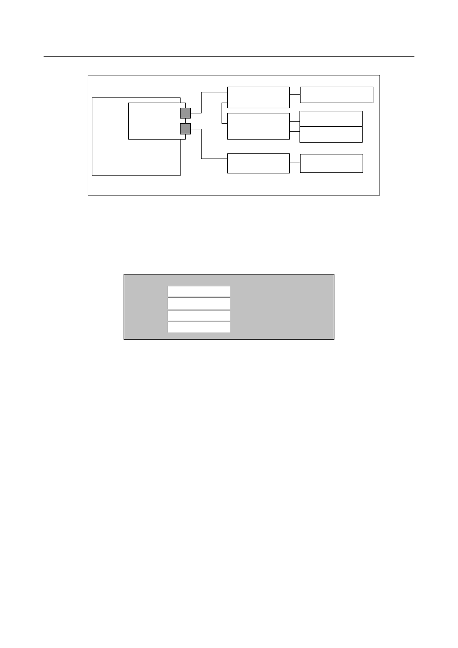
[Example of connection of FSSB] 


CNC 

Servo card 

(Main) 

Spindle amplifier 

Servo amplifier 

Servo amplifier 

Servo motor : X 

Servo motor : Y 

Servo motor : C 

(EGB slave axis) 


Spindle motor : S1 

First FSSB line 

Second FSSB line 

*EGB dummy axis : A 


[Example of parameter setting] 

The following settings are necessary in addition to setting of existing parameters related to the EGB. 


When bit 0 (FHR) of parameter No. 24203 is set to 1, position data transmission  by FSSB is 
enabled. 
And, the index number of the spindle axis that synchronizes with the EGB dummy axis used by 
EGB (FSSB type) is set to the parameter No. 24204 as follows. 

24204 

SP INDEX OF SV FSSB SYNC 


0


0


1


In addition, set 1 to  bit 2 (FSBSYNx) of parameter No. 2429  of EGB dummy axis and bit 2 
(FHESPs) of parameter No. 4549 of S1 spindle axis. 


Ex.2) Two groups of EGB (FSSB type) with C1 – S1 (EGB dummy axis is A1 axis) and C2 – S2 (EGB 

dummy axis is A2 axis) in two paths system 


B-64693EN-1/01


1. AXIS CONTROL


- 355 - 


[Example of connection of FSSB] 


CNC 

Servo card 

(Main) 

Spindle amplifier 

Servo amplifier 

Servo amplifier 
 

Servo motor : X1 

Servo motor : Y1 

Servo motor : X2 

Spindle motor : S1 

Spindle amplifier 

Spindle motor : S2 
 

First FSSB line 

Servo amplifier 
 

Servo amplifier 
 

Servo motor : Y2 

*EGB dummy axis : A2 

*EGB dummy axis : A1 

Servo motor : C1 

(EGB slave axis) 


Servo motor : C2 

(EGB slave axis) 


[Example of parameter setting] 

The following settings are necessary in addition to setting of an existing parameters related to the 
EGB. 


When bit 0 (FHR) of parameter No. 24203 is set to 1, position data transmission  by FSSB is 
enabled. 
And, the index number of the spindle axis that synchronizes with the EGB dummy axis used by 
EGB (FSSB type) is set to the parameter No. 24204 as follows. 


Path 1 

24204 

SP INDEX OF SV FSSB SYNC 


X1 


Y1 


C1 


A1 


Path 2 

24204 

SP INDEX OF SV FSSB SYNC 


X2 


Y2 

0


C2 


A2 


In addition, set 1 to bit 2 (FSBSYNx) of parameter No. 2429 of A1 and A2 axes and bit 2 (FHESPs) 
of parameter No. 4549 of S1 and S2 spindle axes. 

 
Ex.3) EGB (FSSB type) by EGB 2 pair with using common master axis to C1 – S1 (EGB dummy axis is 

A axis) and V1 – S1 (EGB dummy axis is V2 axis) in the one path system 

1. AXIS CONTROL


B-64693EN-1/01


- 356 - 


[Example of connection of FSSB] 


CNC 

Servo card 

(Main) 

Spindle amplifier 

Servo amplifier 

Servo amplifier 
 

Servo motor : X 

Servo motor : Y 

Servo motor : V1 

Spindle motor : S1 

First FSSB line 

Servo amplifier 
 

*EGB dummy axis : V2 

*EGB dummy axis : A 

Servo motor : C 

(EGB slave axis) 


[Example of parameter setting] 

The following settings are necessary in addition to setting of an existing parameters related to the 
EGB. 


When bit 0 (FHR) of parameter No. 24203 is set to 1, position data transmission  by FSSB is 
enabled. 
And, the index number of the spindle axis that synchronizes with the EGB dummy axis used by 
EGB (FSSB type) is set to the parameter No.24204 as follows. 


24204 

SP INDEX OF SV FSSB SYNC 


V1 


V2 


In addition, set 1 to bit 2 (FSBSYNx) of parameter No. 2429 of A and V2 axes and , bit 2 (FHESPs) 
of parameter No. 4549 of S1 spindle axis. 
 
The servo axes that can receive the feedback data from the spindle axis through FSSB are eight axes 
or less in all system. If nine axes or more of the servo axis or illegal index number of the spindle axis 
is set, the alarm (PW0037) “SV/SP COMBINATION ERROR” is issued. 


NOTE 

1  This function can be used by the following EGB functions. 
 

- Electronic gear box 


- U-axis control 


- Signal-based servo EGB synchronous control 

2  As following EGB functions are realized by 2 spindles, it is impossible to apply 

this FSSB type. 


- Spindle electronic gear box 


- Simple spindle electronic gear box 

B-64693EN-1/01


1. AXIS CONTROL


- 357 - 

NOTE 

3  When the parameter is changed, the power must be turned off before an 

operation is continued. 

4  EGB (FSSB type) cannot be used with the analog spindle or the spindle control 

with servo motor. If the above EGB (FSSB type) is set, the alarm (PW0037) 
“SV/SP COMBINATION ERROR” is issued. 

5  When you don’t use spindle sensor and drive the axis only by motor a sensor, 

arbitrary gear ratio between motor and spindle (parameter No.4171-No.4174) is 
used. In the case, please set 1 in bit 1 (EGBAGR) of parameter No.4004. 

6  When you use automatic phase synchronization of EGB (FSSB type) from the 

stop state or slow moving, you have to rotate the spindle axis at least one 
rotation with higher speed than 10min

-1

 before the phase synchronization 

operation. 

7  With EGB dummy axis used by EGB (FSSB type), the following functions cannot 

be used. 


- FSSB high-speed rigid tapping 


- Servo/spindle synchronous control 


- Fully closed control 


If EGB (FSSB type) is used with either of the above functions, the alarm 

(SV0417) “ILL DGTL SERVO PARAMETER” is issued. 

8  When you use U-axis Control or Signal-based Servo EGB Synchronous Control 

by Electronic Gear Box(FSSB type), set “1” to EGB synchronization mode 
selection signal EGBS<Gn067.4> or EGB synchronization start signals 
EGBS1-EGBS8<Gn530> according to following procedure (a) to (c). 


(a) Turn on CNC and confirm the ready of all spindle (All-spindle operation ready 
 

signal SRSRDY<Fn034.7>=”1”). 


(b) Wait about 40msec after (a). 


(c) Set the signal EGBS or EGBS1-EGBS8 to “1”. 


If EGBS<Gn067.4> or EGBS1-EGBS8<Gn530> has been “1” since turning on 
CNC, a shock might occur at the point where the spindle passes the first one 
rotation signal. 

 All-spindle operation ready signal 
SRSRDY<Fn034.7> 

EGB synchronization mode selection 
signal EGBS<Gn067.4>, 
EGB synchronization start signals 
EGBS1-EGBS8<Gn530> 

40msec 


Fig.1.9.8 (a)  EGBS or EGBS1-EGBS8 ON 


1. AXIS CONTROL


B-64693EN-1/01


- 358 - 

Signal 

EGB synchronization mode selection signal 
EGBS<Gn067.4> 

  [Classification]  Input signal 
 

[Function]  Selects the EGB synchronization mode for U-axis control. 


[Operation]  When this signal becomes “1”, the control unit operates as follows: 

Starts EGB synchronization. 


EGB synchronization start signals 
EGBS1<Gn530.0>, EGBS2<Gn530.1>, … 

  [Classification]  Input signal 
 

[Function]  Performs servo EGB synchronous control with the axis of interest used as a slave axis. 


[Operation]  When this signal becomes “1”, the control unit operates as follows:   

Starts servo EGB synchronous control with the axis of interest used as a slave axis. 

When this signal becomes “0”, the control unit operates as follows:   

Cancels servo EGB synchronous control for the axis of interest used as a slave axis. 


NOTE 


If the master axis (spindle) or slave axis (servo axis) is not at halt, 
turning the EGB mode on/off causes the slave axis to 
accelerate/decelerate abruptly. Before turning the EGB mode 
on/off, be sure to keep both the master and slave axes at halt. 


All-spindle operation ready signal 
SRSRDY <Fn034.7> 

  [Classification]  Output signal 
 

[Function]  This signal posts that all spindles used are ready for operation. 


[Operation]  This signal becomes “1” when: 


All used spindles become ready for operation. 

It becomes “0” when: 
 

Some of the used spindles are not ready for operation. 


Signal Address 


#7 

#6 

#5 

#4 

#3 

#2 

#1 

#0 

Gn067 


EGBS 


Gn530 


EGBS8 

EGBS7 

EGBS6 

EGBS5 

EGBS4 

EGBS3 

EGBS2 

EGBS1 


Fn034 


SRSRDY 


Parameter 


#7 

#6 

#5 

#4 

#3 

#2 

#1 

#0 

2429 


FSBSYNx 


[Input type]  Parameter input 


[Data type]  Bit axis 


#2  FSBSYN

x  Servo control by EGB (FSSB type) is: 

0: 

Disabled. 

1: 

Enabled. 


B-64693EN-1/01


1. AXIS CONTROL


- 359 - 

NOTE 

1  When using EGB (FSSB type), set this parameter to 1. 
2  In the EGB dummy axis, in which bit 2 (FSBSYNx) of parameter 

No.2429 is 1, the following functions cannot be used. If EGB 
(FSSB type) is used with either of the following functions, the alarm 
(SV0417) “ILL DGTL SERVO PARAMETER” is issued. (Detail 
number of diagnosis data No.0352 :4292 or 4291) 
- FSSB high-speed rigid tapping (Bit 1 (FHRSVx) of parameter 
  No.2429) 
- Servo/spindle synchronous control (Bit 4 (SPSx) of parameter 
  No.2016) 
 

3  When this parameter is set, the power must be turned off before 

operation is continued. 


#7 

#6 

#5 

#4 

#3 

#2 

#1 

#0 

4004 


EGBAGR 


[Input type]  Parameter input 


[Data type]  Bit spindle 


#1  EGBAGR

  Arbitrary gear ratio between the motor and spindle (parameter No.4171-No.4174) by 

EGB (FSSB type) is: 
0: 

Disabled. 

1: 

Enabled. 


NOTE 

1  To use arbitrary gear ratio between the motor and spindle in case 

of using a motor sensor only without a spindle sensor, set the 
parameter EGBAGR to 1. 
For details of parameter of arbitrary gear ratio (No.4171-No.4174), 
refer to spindle parameter manual (B-65280). 

2  To use this function bit, it’s necessary to prepare the applicable 

CNC software and spindle software. 

3  When bit 1 (EGBAGR) of parameter No.4004 is 0, the feedback 

pulsed from EGB master axis doesn’t take the arbitrary gear ratio 
into account. 

4  Do not change parameter of arbitrary gear ratio and clutch/gear 

signals (CTH) during EGB mode. If parameters or signals are 
changed, the alarm (SP9167) "Spindle control sequence fault" and 
the alarm (SV0385) "Serial data error (EXT)" will occur. 


#7 

#6 

#5 

#4 

#3 

#2 

#1 

#0 

4549 


FHESPs 


[Input type]  Parameter input 


[Data type]  Bit spindle 


#2  FHESP

s  Spindle control by EGB (FSSB type) is: 

0: 

Disabled. 

1: 

Enabled. 


1. AXIS CONTROL


B-64693EN-1/01


- 360 - 

NOTE 

1  When using EGB (FSSB type), set this parameter to 1. 
2  In the spindle axis, in which bit 2 (FHESPs) of parameter No.4549 

is 1, FSSB high-speed rigid tapping (bit 1 (FHRSPs) of parameter 
No.4549) cannot be used. If EGB (FSSB type) is used with the 
FSSB high-speed rigid tapping, the alarm (SP9068) “ILLEGAL 
SPINDLE PARAMETER” is issued. 


#7 

#6 

#5 

#4 

#3 

#2 

#1 

#0 

24203 


FHR 


NOTE 


When the parameter is set, the power must be turned off before 
operation is continued. 


[Input type]  Parameter input 


[Data type]  Bit 


#0  FHR

  Position data transmission by FSSB is: 

0: 

Disabled. 

1: 

Enabled. 


NOTE 

1  In addition, it is necessary to set parameter No.24204. 
2  When the following function is used, set 1 to this parameter. 

- FSSB high-speed rigid tapping 


- Electronic gear box (FSSB type) 


- Servo/Spindle synchronous control (FSSB type) 


24204 


The index number of the spindle axis that synchronizes to each servo axis 


NOTE 


When the parameter is set, the power must be turned off before 
operation is continued. 


[Input type]  Parameter input 


[Data type]  Byte axis 

[Valid data range]  0 to the maximum number of spindles 

Set the index  number of the spindle axis that synchronizes with  EGB dummy  axis  used 
by EGB (FSSB type).   


NOTE 

1  When bit 0 (FHR) of parameter No.24203 is 1, this parameter is 

enabled. 

2  Eight or less index numbers of the spindle axis can be set in the 

system. If nine or more index numbers of the spindle axis are set, 
the alarm (PW0037) "SV/SP COMBINATION ERROR" is issued. 


B-64693EN-1/01


1. AXIS CONTROL


- 361 - 

Reference) Existing parameters related to the EGB. 

Parameter 

number 

Description 

1006#0 
1006#1 

To specify the distance for the slave axis by L in the synchronization command, an EGB slave 
axis and an EGB dummy axis require that the setting of a rotary axis (type A) (bit 0 (ROT) of 
parameter No. 1006 be 1 and bit 1 (ROS) of parameter No. 1006 be 0. 

1023 

Set from the FSSB setting screen. For FSSB manual setting, be sure to set the EGB axis as 
described below: 
The slave axis must be set with an odd number, and the dummy axis with an even number. 
They must be consecutive. 
Example: 
 

If the servo axis number of the slave axis is 1, the servo axis number of the dummy axis 
must be set to 2. If the servo axis number of the slave axis is 3, the servo axis number of 
the dummy axis must be set to 4. 

2011#0 

Specify an axis to be synchronized. Specify 1 for both an EGB slave axis and EGB dummy axis. 

2084/2085 

Flexible feed gear. The feed back data from spindle position sensor is regarded as 2

24


pulses/rev for input to dummy axis. If you want to thin it out, please use Flexible feed gear in 
dummy axis. (See following figure) 

3115#0 

The current position is not indicated for an axis for which this parameter is set to 1.Since the 
current position for an EGB dummy axis has no meaning, set this parameter to 1 to delete the 
current position indication for the axis from the screen. 

7700#0 

The synchronization mode is canceled (0)/not canceled (1) by a reset. 

7700#2 

Compensation direction for helical gear compensation 

7701#3 

At the start of synchronization (G81), synchronization is started (0)/not started (1) if the number 
of hob threads L is specified as 0. 

7702#0 

The specifiable number of teeth, T, at the start of synchronization (G81) is not reduced to a 1/10 
of a specified value (0)/reduced (1). 

7702#3 

The retract function with an alarm is disabled (0)/enabled (1). 

7703#0 

During synchronization (G81), feed per revolution is performed for feedback pulses (0)/pulses 
converted to the speed for the workpiece axis(1). 

7703#1,#2 

Specify when to perform a retract operation with the retract function with an alarm; during 
synchronization; during synchronization and automatic operation; or during synchronization or 
automatic operation. 

7709 

Number of the axial feed axis in helical gear compensation 

7731#0 

The EGB command is G80 and G81(0)/G80.4 and G81.4(1). 

7731#3 

When the automatic phase synchronization function for the electronic gear box is disabled, the 
G81 command cannot be issued again (an alarm is issued) (0)/can be issued again (1) during 
EGB synchronization. 

7731#5 

In EGB synchronization start command G81.4, the number of teeth is specified in T 
(0)/specified in R (1). 

7740 

Feedrate during retraction 

7741 

Retract amount 

7772 

Number of position detector pulses per rotation about tool axis. Please set the value which 
takes the Flexible feed gear and EGB exponent setting into consideration. (See following 
figure.) 

7773 

Number of position detector pulses per rotation about workpiece axis 

7782 

Pulse count of position detector per rotation about EGB master axis 

7783 

Pulse count of position detector per rotation about EGB slave axis 

7784 

Numerator of a signal-based servo EGB synchronization ratio 

7785 

Denominator of a signal-based servo EGB synchronization ratio 

7786#0 

The signal-based servo EGB synchronization function is invalid (0) / valid (1). 


Content      ..     48      49      50      51     ..