FANUC Series 0i-MODEL F Plus. CONNECTION MANUAL (FUNCTION) - page 41
 

  Index      Manuals     FANUC Series 0i-MODEL F Plus. CONNECTION MANUAL (FUNCTION) B-64693EN-1/01


Search            copyright infringement  


Content      ..     39      40      41      42     ..


FANUC Series 0i-MODEL F Plus. CONNECTION MANUAL (FUNCTION) - page 41


1. AXIS CONTROL


B-64693EN-1/01


- 282 - 

where 

Compensation angle: Signed absolute value (deg) 

Amount of travel on the Z-axis after the specification of G81 

Signed gear helix angle (deg) 

π


Circular constant 

Number of teeth 

Module (mm) or diametral pitch (inch

-1

Use P, T, and Q specified in the G81 block. 
In helical gear compensation, the machine coordinates on the workpiece axis and the absolute coordinates 
are updated with helical gear compensation. 
The updated timing is as follows. 

Machine coordinates 

Absolute coordinates 

During helical gear compensation 

Bit 7(HAD) of parameter No.7731 

= 0 

= 1 

Synchronization cancel 

During helical gear compensation 


  - 

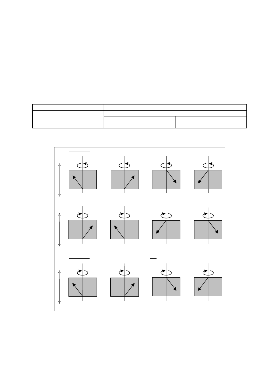
Direction of helical gear compensation 

The direction depends on bit 2 (HDR) of parameter No. 7700. 


When HDR = 1 

+C 

C : +, Z : +, P : + 

Compensation direction:+


(a) 

-

Z


+Z 

+C 

C : +, Z : +, P : - 

Compensation direction:-


(b) 

+C 

C : +, Z : -, P : + 

Compensation direction:-


(c) 

+C 

C : +, Z : -, P : - 

Compensation direction:+


(d) 

-

Z


+

Z


C : -, Z : +, P : + 

C : Compensation direction:-


(e) 

-

C


C : -, Z : +, P : - 

Compensation direction:+


(f) 

-

C


C : -, Z : -, P : + 

Compensation direction:+


(g) 

-

C


C : -, Z : -, P : - 

Compensation direction:-


(h) 

-

C


When HDR = 0 ((a), (b), (c), and (d) are the same as when HDR = 1)


-Z 

+

Z


C : -, Z : +, P : + 

Compensation direction:+


(e) 

-

C


C : -, Z : +, P : - 

Compensation direction:-


(f) 

-

C


C : -, Z : -, P : + 

Compensation direction:-


(g) 

-

C


C : -, Z : -, P : - 

Compensation direction:+


(h) 

-

C


Fig. 1.9.2 (c) Direction of helical gear compensation 


B-64693EN-1/01


1. AXIS CONTROL


- 283 - 

  - 

Synchronization coefficient 

A synchronization coefficient is internally represented using a fraction (K

2

/K

1

) to eliminate an error. The 

formula below is used for calculation. 

α

β

T

L

K

K


=

coefficien

ation 

Synchroniz

1

2

×

=


where 
L :  Number of hob threads 
T :  Number of teeth 

a

 :  Number of pulses of the position detector per rotation about the master axis (parameter No. 7772) 

β

 :  Number of pulses of the position detector per rotation about the slave axis (parameter No. 7773) 

 
K

2

/K

1

 is a value resulting from reducing the right side of the above formula, but the result of reduction is 

subject to the following restrictions: 
-32767

K

2

32767 

1

K

1

32767 

When this restriction is not satisfied, the alarm PS1596  “EGB OVERFLOW”  is issued when  G81 is 
specified. 
 
The values of K

2

 and K

1

 are set in parameters Nos. 4387 and 4388 automatically when G81 is specified. 

If T is not specified in the G81 block, alarm PS1594 “EGB FORMAT ERROR”  is issued. If L is not 
specified in that block, the synchronization coefficient is calculated, assuming L = 1. 
 
Example) 
 

When the number of pulses that correspond to one rotation (360000) is specified for the tool axis 
(master axis) under the following conditions, the position command pulses are distributed as shown 
in Fig. 1.10.2 (d). 


Number of hob threads L: 10 


Number of teeth 

T: 100 


Number of pulses of the position detector per rotation about the tool axis


: 360000 


Number of pulses of the position detector per rotation about the workpiece axis  : 360000 


10

1

360000

360000

100

10

α

β

T

L

K

K

t

coefficien

ation 

Synchroniz

1

2

=

×

=

×

=

=


Position feedback


36000 

360000 

+


EGB 

Slave axis 

Cs command


×

K

2

/K

1


(

×

1/10) 

×

CMR


(

×

1

Motor


Workpiece


Detector


K

2

/K

1

:  Synchronization 

coefficient


+


0


0


+


Motor


Tool axis


Detector


36000 

Master axis 

Cs command


×

CMR


(

×

1

360000 

360000 


Fig. 1.9.2 (d) Command pulse distribution 


1. AXIS CONTROL


B-64693EN-1/01


- 284 - 


As shown in Fig. 1.10.2 (d), when 360000 pulses (number of pulses required for one rotation about 
the master axis) are specified for the master axis, the value of the position command to the slave axis 
by EGB is obtained by multiplying the number of pulses required for one rotation about the slave 
axis by the ratio of the number of hob threads to the number of teeth (rotation ratio of the slave axis 
to the master axis): 


360000 

×

  1/10 = 36000 


Retract function 

See Item, “Retract function” in the Subsection “Electronic Gear Box”. 
 

Signal 

EGB mode signal SYNMOD <Fn065.6> 

  [Classification]  Output signal 
 

  [Function]  Posts notification that synchronization using the EGB is in progress. 


  [Operation]  This signal is set to “1” in the following case: 

While synchronization using the EGB is in progress 

This signal is set to “0” in the following case: 

Once synchronization using the EGB has terminated 


Signal address 


#7 

#6 

#5 

#4 

#3 

#2 

#1 

#0 

Fn065 


SYNMOD 


Parameter 

The table below gives parameters related to spindle EGB. 

Parameter 

number 

Description 

1006#0 
1006#1 

An EGB slave axis requires that the setting of a rotary axis (type A) (bit 0 (ROT) of parameter 
No. 1006 be 1 and bit 1 (ROS) of parameter No. 1006 be 0. 

4036 

Feed forward coefficient for serial spindle 

4352#4 

Feed forward setting 

4352#6 

Setting of the spindle EGB slave axis 

4352#7 

Setting of the spindle EGB master axis 

4386 

Number of sinusoidal waves from the master spindle position detector 

4387 

Numerator of synchronization coefficient 

4388 

Denominator of synchronization coefficient 

7700#0 

The synchronous mode is canceled (0)/not canceled (1) by a reset. 

7700#2 

Compensation direction for helical gear compensation 

7701#3 

At the start of synchronization (G81), synchronization is started (0)/not started (1) if the number 
of hob threads L is specified as 0. 

7702#0 

The specifiable number of teeth, T, at the start of synchronization (G81) is not reduced to a 1/10 
of a specified value (0)/reduced (1). 

7702#3 

The retract function with an alarm is disabled (0)/enabled (1). 

7703#0 

During synchronization (G81), feed per revolution is performed for feedback pulses (0)/pulses 
converted to the speed for the workpiece axis(1). 

7703#1,#2 

Specify when to perform a retract operation with the retract function with an alarm; during 
synchronization; during synchronization and automatic operation; or during synchronization or 
automatic operation. 

7709 

Number of the axial feed axis in helical gear compensation 

7710 

The controlled axis number for the spindle EGB slave axis 

7731#0 

The EGB command is G80 and G81(0)/G80.4 and G81.4(1). 

7731#5 

In EGB synchronization start command G81.4, the number of teeth is specified in T 
(0)/specified in R (1). 

7740 

Retraction speed 

B-64693EN-1/01


1. AXIS CONTROL


- 285 - 

Parameter 

number 

Description 

7741 

Retract amount 

7772 

Number of position detector pulses per rotation about tool axis 

7773 

Number of position detector pulses per rotation about workpiece axis 


4036 


Feed forward coefficient for serial spindle 


[Input type]  Parameter input 


[Data type]  Word spindle 


[Unit of data]  1% 

[Valid data range]  0 to 10000 

This parameter sets the feed forward coefficient in the Cs axis contour control mode. 
When the setting is smaller than or equal to 100: In units of 1% 
When the setting is greater than 100: In units of 0.01% 
Set 100 for the slave spindle. 


#7 

#6 

#5 

#4 

#3 

#2 

#1 

#0 

4352 


SPEGBM 

SPEGBS 


FFALWS 


[Input type]  Parameter input 


[Data type]  Bit spindle 


  #4  FFALWS

  Feed forward setting 

0: 

Feed forward is enabled only in cutting feed. 

1: 

Feed forward is always enabled. 

Set 1 for the slave spindle. 


    #6  SPEGBS

  The spindle EGB function for slave spindle is: 

0: 

Disabled. 

1: 

Enabled. 

Set 1 for the slave spindle. 


  #7  SPEGBM

  The spindle EGB function for master spindle is: 

0: 

Disabled. 

1: 

Enabled. 

Set 1 for the master spindle. 


4386 


Number of sinusoidal waves from the master spindle position detector 


[Input type]  Parameter input 


[Data type]  Word spindle 


[Unit of data]  1

λ

/rev


[Valid data range]  0

64 to 4096 

This parameter sets the number of sinusoidal waves per spindle rotation from the master 
spindle position detector. 
Set this parameter for the slave spindle amplifier. 
Setting 0 in this parameter is equivalent to setting the synchronization coefficient to 0. 
 

1. AXIS CONTROL


B-64693EN-1/01


- 286 - 

4387 


Numerator of synchronization coefficient 


[Input type]  Parameter input 


[Data type]  Word spindle 

[Valid data range]  -32767 to 32767 

The numerator of the synchronization coefficient is set in this parameter automatically 
when G81 is specified. 


4388 


Denominator of synchronization coefficient 


[Input type]  Parameter input 


[Data type]  Word spindle 

[Valid data range]  1 to 32767 

The denominator of the synchronization coefficient is set in this parameter automatically 
when G81 is specified. 


#7 

#6 

#5 

#4 

#3 

#2 

#1 

#0 

7700 


HDR 


HBR 


[Input type]  Parameter input 


[Data type]  Bit path 


#0  HBR

  When the electronic gear box (EGB) function is used, performing a reset: 

0: 

Cancels the synchronous mode (G81 or G81.5). 

1: 

Does not cancel the synchronous mode. The mode is canceled only by the G80 or 
G80.5 command. 


#2  HDR

  Direction of helical gear compensation (usually, set 1.) 


  (Example) To cut a left-twisted helical gear when the direction of rotation about the 

C-axis is the negative (-) direction: 
0: 

Set a negative (-) value in P. 

1: 

Set a positive (+) value in P. 


B-64693EN-1/01


1. AXIS CONTROL


- 287 - 


When HDR = 1 

+C 

C : +, Z : +, P : + 

Compensation direction:+


(a) 

-

Z


+Z 

+C 

C : +, Z : +, P : - 

Compensation direction:-


(b) 

+C 

C : +, Z : -, P : + 

Compensation direction:-


(c) 

+C 

C : +, Z : -, P : - 

Compensation direction:+


(d) 

-

Z


+

Z


C : -, Z : +, P : + 

C : Compensation direction:-


(e) 

-

C


C : -, Z : +, P : - 

Compensation direction:+


(f) 

-

C


C : -, Z : -, P : + 

Compensation direction:+


(g) 

-

C


C : -, Z : -, P : - 

Compensation direction:-


(h) 

-

C


When HDR = 0 ((a), (b), (c), and (d) are the same as when HDR = 1)


-Z 

+

Z


C : -, Z : +, P : + 

Compensation direction:+


(e) 

-

C


C : -, Z : +, P : - 

Compensation direction:-


(f) 

-

C


C : -, Z : -, P : + 

Compensation direction:-


(g) 

-

C


C : -, Z : -, P : - 

Compensation direction:+


(h) 

-

C


Fig. 1.9.2 (e) Direction of helical gear compensation 


#7 

#6 

#5 

#4 

#3 

#2 

#1 

#0 

7701 


LZR 


[Input type]  Parameter input 


[Data type]  Bit path 


#3  LZR

  When L (number of hob threads) = 0 is specified at  the start of EGB synchronization 

(G81): 
0: 

Synchronization is started, assuming that L = 1 is specified. 

1: 

Synchronization is not started, assuming that L = 0 is specified. However, helical 
gear compensation is performed. 


#7 

#6 

#5 

#4 

#3 

#2 

#1 

#0 

7702 


ART 


TDP 


[Input type]  Parameter input 


[Data type]  Bit path 


#0  TDP

  The specifiable number of teeth, T, of the electronic gear box (G81) is: 

0: 

1 to 5000 

1: 

0.1 to 500 (1/10 of a specified value) 


NOTE 


In either case, a value from 1 to 5000 can be specified. 

1. AXIS CONTROL


B-64693EN-1/01


- 288 - 


#3  ART

  The retract function executed when an alarm is issued is: 

0: 

Disabled. 

1: 

Enabled. 

When an alarm is issued, a retract operation is performed with a set feedrate and travel 
distance (parameters Nos. 7740 and 7741). 
 

NOTE 


If a servo alarm is issued for other than the axis along which a 
retract operation is performed, the servo activating current is 
maintained until the retract operation is completed. 


#7 

#6 

#5 

#4 

#3 

#2 

#1 

#0 

7703 


ARO 

ARE 

ERV 


[Input type]  Parameter input 


[Data type]  Bit path 


#0  ERV

  During EGB synchronization (G81), feed per revolution is performed for: 

0: 

Feedback pulses. 

1: 

Pulses converted to the speed for the workpiece axis. 


#1  ARE

  The retract function executed when an alarm is issued retracts the tool during: 

0: 

EGB synchronization or automatic operation (automatic operation signal OP 
<Fn000.7> = “1”). 

1: 

EGB synchronization. 


#2  ARO

  The retract function executed when an alarm is issued retracts the tool during: 

0: 

EGB synchronization. 

1: 

EGB synchronization and automatic operation (automatic operation signal OP = 
“1”). 


NOTE 


This parameter is valid when bit 1 (ARE) of parameter No. 7703 is 
set to “1”. 

 
The following table lists the parameter settings and corresponding operation. 
 

ARE 

ARO 

Operation 

During EGB synchronization 

During EGB synchronization and automatic operation 

During EGB synchronization or automatic operation 


NOTE 


Parameters ARE and ARO are valid when bit 3 (ART) of parameter 
No. 7702 is set to 1 (when the retract function executed when an 
alarm is issued). 


B-64693EN-1/01


1. AXIS CONTROL


- 289 - 

7709 


Number of the axial feed axis for helical gear compensation 


[Input type]  Parameter input 


[Data type]  2-word path 

[Valid data range]  0 to Number of controlled axes 

This parameter sets the number of the axial feed axis for a helical gear. 
 

NOTE 


When this parameter is set to 0 or a value outside the valid setting 
range, the Z-axis becomes the axial feed axis. 


7710 


Controlled axis number for the spindle EGB slave axis 


[Input type]  Parameter input 


[Data type]  2-word path 

[Valid data range]  0 to Number of controlled axes 

This parameters sets the controlled axis number for the spindle EGB slave axis. 
 

NOTE 

1  Set this parameter when there are two or more groups of servo and 

spindle EGBs in the same path. Set 0 when there is one group of 
EGBs in the same path. 

2  When there are two or more groups of servo and spindle EGBs in 

the same path, setting a value outside the valid data range in this 
parameter causes alarm PS1593 to be issued. 

3  For Series 16

i

, when a value outside the valid data range is set in 

this parameter, the fourth axis is assumed according to the 
specifications. 

4  The setting of this parameter becomes valid after the power is 

turned off then back on. 


#7 

#6 

#5 

#4 

#3 

#2 

#1 

#0 

7731 


HAD 


HBR 


EFX 


[Input type]  Parameter input 


[Data type]  Bit path 


#0  EFX

  As the EGB command: 

0: 

G80 and G81 are used. 

1: 

G80.4 and G81.4 are used. 


NOTE 


When this parameter is set to 0, no canned cycle for drilling can be 
used. 


#5  HBR

  In EGB synchronization start command G81.4, the number of teeth is: 

0: 

Specified in T. 

1: 

Specified in R. 


NOTE 

This parameter is valid when bit 0 (EFX) of parameter No. 7731 is 
set to 1. 


Content      ..     39      40      41      42     ..