FANUC Series 0i-MODEL F Plus. CONNECTION MANUAL (FUNCTION) - page 10
 

  Index      Manuals     FANUC Series 0i-MODEL F Plus. CONNECTION MANUAL (FUNCTION) B-64693EN-1/01


Search            copyright infringement  


Content      ..     8      9      10      11     ..


FANUC Series 0i-MODEL F Plus. CONNECTION MANUAL (FUNCTION) - page 10


1. AXIS CONTROL


B-64693EN-1/01


- 34 - 

1.2.11 

Axis Total Travel Distance Display 

Overview 

Total travel distance of axis is calculated, the distance of each axis is displayed on the diagnosis screen. If 

target distance is set, signal indicates that the travel distance exceeds the target. 


Explanation 

  -  Display of total travel distance 

Total travel distance of axis is displayed on diagnosis data Nos. 365 and 366.  When  bit 3 (ETD) of 

parameter No. 8906 is 1, this function is valid. 

Diagnosis data No. 365 becomes 0 when total travel distance clear signal TDCx<Gn726> is set to "1" 

from "0". 

Diagnosis data No. 366 becomes 0 when it exceeds the upper limit. 

When bit 3 (ETD) of parameter No. 8906 is 0, this function is executed as follows: 

- Total travel distance is not calculated. However, the value calculated in the past is displayed. 

- Diagnosis data No. 365 is not cleared by total travel distance clear signal TDCx<Gn726>. 


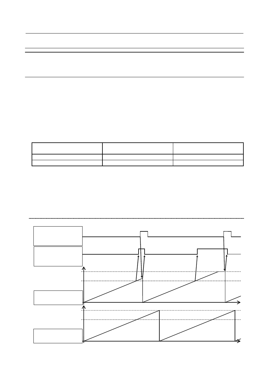
Total travel distance clear signal 
TDCx<Gn726> is set to "1" from "0" 

Travel distance exceeds the upper 
limit. 

Diagnosis data No. 365 

Becomes 0 

Keeps the upper limit 

Diagnosis data No. 366 

Doesn’t become 0 

Becomes 0 


  -  Indication of target distance attainment 

When total travel distance (diagnosis data No. 365) exceeds the target distance set in parameter No. 8852, 

target distance attainment status signal TDAx<Fn730> becomes "1".  Even if travel distance exceeds 

target, the accumulation of diagnostic data(No.365) continues. 

When bit 3 (ETD) of parameter No. 8906 is 1, this function is valid. If bit 3 (ETD) of parameter No. 8906 

is 0 or the value set in parameter No.8852 is outside the data range, target distance attainment status 

signal TDAx<Fn730> always becomes 0. 


Timing chart 


Upper limit


Parameter No.8852


Upper limit


Parameter No.8852


Total travel distance   

clear signal   

TDCx<Gn726>


Target distance   

attainment status   

signal TDAx<Fn730>


diagnosis data   

No. 365


diagnosis data   

No. 366


B-64693EN-1/01


1. AXIS CONTROL


- 35 - 

NOTE 

1  Total travel distance is not calculated at the following command: 

  - Feedrate control of PMC axis control of when bit 2 (VCP) of parameter No. 8007 

is 1 and bit 4 (EVP) of parameter No. 8005 is 0. 

  - Torque control of PMC axis control of when follow-up is not performed (bit 4 

(TQF) of parameter No. 1803 is 0). 

2  Total travel distance of axis to which servo is invalid (bit 4 (KSVx) of parameter 

No. 11802) is not calculated. 

3  In the axis during servo-off with follow-up (bit 0 (FUPx) of parameter No.1819 is 0 

and follow-up signal *FLWU<Gn007.5> is “0”), the travel distance by the external 

force is added to total travel distance. 


Parameter 


#7 

#6 

#5 

#4 

#3 

#2 

#1 

#0 

8906 


ETD 


[Input type]  Parameter input 


[Data type]  Bit 


NOTE 

  When at least one of these parameters is set, the power must be 

turned off before operation is continued. 


#3  ETD

  Axis total travel distance display is: 

0:  Invalid. 

1:  Valid. 


8852 


Target distance of each axis 


[Input type]  Parameter input 


[Data type]  2-word axis 


[Unit of data]  m, 100 inch, 360 deg 

[Valid data range]  1 to 999999999 

When diagnosis data No. 365 exceeds the value set in this parameter, target distance 

attainment status signal TDAx<Fn730> become "1". 


NOTE 

1  In case of rotation axis, unit of data is 360 degree. In case of linear 

axis, unit of data is m or 100 inch according to the least command 

increment. 

2  If the value set in this parameter is outside the data range or bit 3 

(ETD) of parameter No. 8906 is 0, target distance attainment status 

signal TDAx<Fn730> always becomes 0.   

3  This parameter is specified as radius specification. Diameter/radius 

specification does not affect this parameter. 


1. AXIS CONTROL


B-64693EN-1/01


- 36 - 

Signal 

Total travel distance clear signal TDC1 to TDC8<Gn726> 

  [Classification]  Input signal 


[Function]  Total travel distance (diagnosis data No. 365) of the corresponding axis becomes 0. 


[Operation]  When these signals are set to "1" from "0", total travel distance (diagnosis data No. 365) 

of the corresponding axis becomes 0. 


NOTE 

1  When bit 3 (ETD) of parameter No. 8906 is 1, these signals are 

valid. If bit 3 (ETD) of parameter No. 8906 is 0, diagnosis data No. 

365 doesn't become 0. 

2  Set these signals to "0" after confirming either of the following 

conditions: 

- Target distance attainment status signal TDAx<Fn730> becomes 

“0” from “1” 

- Diagnosis data No. 365 becomes 0 

- 128 msec or more have passed since these signals became “1” 


Target distance attainment status signal TDA1 to TDA8<Fn730> 

  [Classification]  Output signal 


[Function]  These signals indicate that the travel distance exceeds the target. 

  [Output cond.]  These signals become “1” when: 

Total travel distance (diagnosis data No. 365) exceeds the target distance set in 

parameter No. 8852. 

These signals become “0” when: 

Total travel distance (diagnosis data No. 365) doesn’t exceed the target distance set 

in parameter No. 8852. 


NOTE 

  When bit 3 (ETD) of parameter No. 8906 is 1, these signals are 

valid. If bit 3 (ETD) of parameter No. 8906 is 0 or the value set in 

parameter No.8852 is outside the data range, these signals always 

become 0. 


Signal address 


#7 

#6 

#5 

#4 

#3 

#2 

#1 

#0 

Gn726 


TDC8 

TDC7 

TDC6 

TDC5 

TDC4 

TDC3 

TDC2 

TDC1 


#7 

#6 

#5 

#4 

#3 

#2 

#1 

#0 

Fn730 


TDA8 

TDA7 

TDA6 

TDA5 

TDA4 

TDA3 

TDA2 

TDA1 


B-64693EN-1/01


1. AXIS CONTROL


- 37 - 

Diagnosis data 

365 


Total travel distance (clearable) 


366 


Total travel distance 


[Data type]  2-word axis 


[Unit of data]  m, 100 inch, 360 deg 

[Valid data range]  0 to 42949672    (When unit of data is m) 

0 to 16909320    (When unit of data is 100 inch) 

0 to 4294967295  (When unit of data is 360 deg) 

Total travel distance of axis is displayed. 

When total travel distance clear signal TDCx<Gn726> is set to "1" from "0", diagnosis 

data No. 365 becomes 0. Diagnosis data No. 366 becomes 0 when it exceeds the upper 

limit. 


Total travel distance clear signal 
TDCx<Gn726> is set to "1" from "0" 

Travel distance exceeds the upper limit. 

Diagnosis data 
No. 365 

Becomes 0 

Keeps the upper limit 

Diagnosis data 
No. 366 

Doesn’t become 0 

Becomes 0 


NOTE 

1  In case of rotation axis, unit of data is 360 degree. In case of linear 

axis, unit of data is m or 100 inch according to the least command 

increment. 

2  If bit 3 (ETD) of parameter No. 8906 is 1, total travel distance is 

calculated. 

3  If bit 3 (ETD) of parameter No. 8906 is 0, total travel distance is not 

calculated. However, the value calculated in the past is displayed.   

4  These diagnosis data are displayed as radius specification. 

Diameter/radius specification does not affect these diagnosis data. 


1.3 

ERROR COMPENSATION 

1.3.1 

Stored Pitch Error Compensation 

Overview 

If pitch error compensation data is specified, pitch errors of each axis can be compensated in detection 

units per axis. 

Pitch error compensation data is set for each compensation position at the intervals specified for each axis. 

The origin of compensation is the reference position to which the tool is returned. 

Pitch error compensation data can be set with external devices such as the Handy File (see OPERATOR'S 

MANUAL). Compensation data can also be set directly with the MDI unit. 

The following parameters must be set for pitch error compensation. Set the pitch error compensation 

value for each pitch error compensation position number set by these parameters. 

In the following example  of Fig. 1.3.1 (a), 33 is set for the pitch error compensation number at the 

reference position. 

1. AXIS CONTROL


B-64693EN-1/01


- 38 - 


Fig. 1.3.1 (a) 


Pitch error compensation position at the reference position (for each axis):  Parameter No.3620 

Pitch error compensation position having the smallest value (for each axis):  Parameter No.3621 

Pitch error compensation position having the largest value (for each axis):  Parameter No.3622 

Pitch error compensation magnification (for each axis): 

Parameter No.3623 

Interval of the pitch error compensation positions (for each axis): 

Parameter No.3624 


Explanation 

  -  Specifying the compensation position 

To assign the compensation positions for each axis, specify the positive direction or the negative direction 

relative to the compensation position No. of the reference position. If the machine stroke exceeds the 

specified range on either the positive direction or the negative direction, the pitch error compensation 

does not apply beyond the range. 


  -  Compensation position number 

1536 compensation positions from No. 0 to 1535 are available on the pitch error setting screen. Assign 

arbitrary positions for each axis using parameters. 

The number of the compensation position at the reference position (parameter No.3620), number of the 

compensation position having the smallest value (parameter No.3621), and number of the compensation 

position having the largest value (parameter No.3622) must be set for each axis. 

The name of each axis is displayed before the smallest compensation position number on the pitch error 

setting screen. 


  -  Interval of compensation positions 

The pitch error compensation positions are equally spaced to parameter No. 3624. Set the space between 

two adjacent positions for each axis. 

The minimum interval between pitch error compensation positions is limited and obtained from the 

following equation: 

Minimum interval of pitch error compensation positions = maximum feedrate (rapid traverse rate)/7500 

Unit : 


Minimum interval of pitch error compensation positions: mm, inches, deg. 


Maximum feed rate: mm/min, inch/min, deg/min 

B-64693EN-1/01


1. AXIS CONTROL


- 39 - 

[Example] 


When the maximum rapid traverse rate is 15000 mm/min, the minimum interval between pitch error 

compensation positions is 2 mm. 


Example 

  -  For linear axis 

Machine stroke: -400 mm to +800 mm 

Interval between the pitch error compensation positions: 50 mm 

No. of the compensation position of the reference position: 40 

If the above is specified, the No. of the farthest compensation position in the negative direction is as 

follows: 

No. of the compensation position of the reference position - (Machine stroke on the negative side/Interval 

between the compensation positions) + 1= 40 - 400/50 + 1= 33 

No. of the farthest compensation position in the positive direction is as follows: 

No. of the compensation position of the reference position + (Machine stroke on the positive side/Interval 

between the compensation positions)= 40 + 800/50= 56 

A fraction of the division of machine stroke on the negative/positive  side  by interval between the 

compensation positions is raised up to an integer. 

The correspondence between the machine coordinate and the compensation position No. is as  Fig. 

1.3.1(b): 

33

39

40

41

42

56

-400 -350 -100

-50

0

50

100

750

800

Machine

coordinate

(mm)

Compensation

position

number

Compensation values are output at the positions indicated by    .


Fig. 1.3.1 (b) 


Therefore, set the parameters as Table 1.3.1 (a): 


Table 1.3.1 (a) 

Parameter 

Setting value 

3620 : Compensation number for the reference position 

40 

3621 : Smallest compensation position number 

33 

3622 : Largest compensation position number 

56 

3623 : Compensation magnification 

3624 : Interval between pitch error compensation positions 

50.0 


The compensation amount is output at the compensation position No. corresponding to each section 

between the coordinates.   

The Fig. 1.3.1 (c) is an example of the compensation amounts. 

1. AXIS CONTROL


B-64693EN-1/01


- 40 - 


Fig. 1.3.1 (c) 


  -  For rotary axis 

Amount of movement per rotation: 360

°


Interval between pitch error compensation positions: 45

°


No. of the compensation position of the reference position: 60 

In the above case, the number of the most distance compensation position on the - side is equal to the 

number of the compensation position of the reference position + 1 = 60 + 1 = 61 for a rotary axis. 

The No. of the farthest compensation position in the positive direction is as follows: 

No. of the compensation position of the reference position + (Move amount per rotation/Interval between 

the compensation positions)= 60 + 360/45= 68 

The correspondence between the machine coordinate and the compensation position No. is as Fig. 1.3.1 

(d): 


0.0 

45.0 

90.0 

135.0 

180.0 

225.0 

270.0 

315.0 

(68) 

(60) 

(67) 

(66) 

(65) 

(64) 

(63) 

(62) 

(61) 

(+) 

Reference position 

Compensation values are output at 

the positions indicated by      . 


Fig. 1.3.1 (d) 


Therefore, set the parameters as Table 1.3.1 (b): 

Table 1.3.1 (b) 

Parameter 

Setting value 

3620 : Compensation number for the reference position 

60 

3621 : Smallest compensation position number 

61 

3622 : Largest compensation position number 

68 

3623 : Compensation magnification 

3624 : Interval between pitch error compensation positions 

45.0 

3625 : Movement value per rotation 

360.0 


B-64693EN-1/01


1. AXIS CONTROL


- 41 - 

If the sum of the compensation values for positions 61 to 68 is not 0, pitch error compensation values are 

accumulated for each rotation, causing positional deviation. 

The same value must be set for compensation positions 60 and 68. 


The Fig. 1.3.1 (e) is an example of compensation amounts. 

60 61 62 63 64 65 66 67 68

+1 -2 +1 +3 -1 -1 -3 +2 +1

Number

Compensation

value

(deg)

0

61 62 63 64 65 66 67

68

(60)

-1
-2
-3
-4

+1

+2

+3

+4

Pitch error

compensation value

(absolute value)

45 90135180225270315

61 62 63 64 65 66 67

45 90135180225270315

0

61 62

45 90

68

(60)

Reference position


Fig. 1.3.1 (e) 


Procedure for displaying and setting the pitch error compensation data 

Procedure 

1  Set the following parameters: 

Number of the pitch error compensation point at the reference 

position (for each axis) 

:  Parameter No. 3620 

Number of the pitch error compensation point having the smallest 

value (for each axis) 

:  Parameter No. 3621 

Number of the pitch error compensation point having the largest 

value (for each axis) 

:  Parameter No. 3622 

Pitch error compensation magnification (for each axis) 

:  Parameter No. 3623 

Interval of the pitch error compensation points (for each axis) 

:  Parameter No. 3624 

Travel distance per revolution of pitch error compensation of the 

rotary axis type (for each axis) 

:  Parameter No. 3625 


When using bi-directional pitch error compensation (setting bit 0 (BDPx) of parameter No. 3605 to 

1), specify the following parameters in addition to the pitch error compensation parameter. 

Number of the pitch error compensation point at the negative end 

(for travel in the positive direction, for each axis) 

:  Parameter No. 3621 

Number of the pitch error compensation point at the positive end 

(for travel in the positive direction, for each axis) 

:  Parameter No. 3622 

Number of the pitch error compensation point at the negative end 

(for travel in the negative direction, for each axis) 

:  Parameter No. 3626 

Pitch error compensation in the reference position when moving to 

the reference position from opposite to the reference position return 

direction (for each axis) 

:  Parameter No. 3627 

2  Press function key 


3  When the display unit is 10.4-inch, press the continuous menu key 


, then press chapter selection 

soft key [PITCH ERROR]. The following screen is displayed: 


Content      ..     8      9      10      11     ..