Cisco IE 2000 Switch Hardware Installation Guide (2016) - page 1
Cisco IE 2000 Switch Hardware Installation
Guide
First Published: June 2012
Last Updated: May 2016
THE SPECIFICATIONS AND INFORMATION REGARDING THE PRODUCTS IN THIS MANUAL ARE SUBJECT TO CHANGE
WITHOUT NOTICE. ALL STATEMENTS, INFORMATION, AND RECOMMENDATIONS IN THIS MANUAL ARE BELIEVED TO BE
ACCURATE BUT ARE PRESENTED WITHOUT WARRANTY OF ANY KIND, EXPRESS OR IMPLIED. USERS MUST TAKE FULL
RESPONSIBILITY FOR THEIR APPLICATION OF ANY PRODUCTS.
THE SOFTWARE LICENSE AND LIMITED WARRANTY FOR THE ACCOMPANYING PRODUCT ARE INCORPORATED HEREIN BY
THIS REFERENCE. IF YOU ARE UNABLE TO LOCATE THE SOFTWARE LICENSE OR LIMITED WARRANTY, CONTACT YOUR
CISCO REPRESENTATIVE FOR A COPY.
The following information is for FCC compliance of Class A devices: This equipment has been tested and found to comply with
the limits for a Class A digital device, pursuant to part 15 of the FCC rules. These limits are designed to provide reasonable
protection against harmful interference when the equipment is operated in a commercial environment. This equipment
generates, uses, and can radiate radio-frequency energy and, if not installed and used in accordance with the instruction
manual, may cause harmful interference to radio communications. Operation of this equipment in a residential area is likely to
cause harmful interference, in which case users will be required to correct the interference at their own expense.
The following information is for FCC compliance of Class B devices: This equipment has been tested and found to comply with
the limits for a Class B digital device, pursuant to part 15 of the FCC rules. These limits are designed to provide reasonable
protection against harmful interference in a residential installation. This equipment generates, uses and can radiate radio
frequency energy and, if not installed and used in accordance with the instructions, may cause harmful interference to radio
communications. However, there is no guarantee that interference will not occur in a particular installation. If the equipment
causes interference to radio or television reception, which can be determined by turning the equipment off and on, users are
encouraged to try to correct the interference by using one or more of the following measures:
■ Reorient or relocate the receiving antenna.
■ Increase the separation between the equipment and receiver.
■ Connect the equipment into an outlet on a circuit different from that to which the receiver is connected.
■ Consult the dealer or an experienced radio/TV technician for help.
Modifications to this product not authorized by Cisco could void the FCC approval and negate your authority to operate the
product.
2
Contents
Preface
5
Audience
5
Purpose
5
Conventions
5
Related Publications
6
Product Overview
7
Overview
7
Switch Models
8
Front Panel Overview
10
Ports and Slots
14
10/100BASE-T Downlink Ports
15
10/100BASE-T Uplink Ports
15
10/100/1000BASE-T Uplink Ports
15
100 Mb/s SFP Module Downlink Slots
15
100/1000 Mb/s SFP Module Uplink Slots
15
10/100/1000BASE-T Copper SFP Module Uplink Slots
15
Dual-Purpose Fast Ethernet Uplink Ports
15
Dual-Purpose Gigabit Ethernet Uplink Ports
16
Power over Ethernet Ports
16
Management Ports
16
Power Connectors
17
DC Power Connector
17
PoE Power Connector
17
Alarm Connector
18
SFP Modules
19
SFP Module Patch Cable
20
LEDs
20
Express Setup LED
21
System LED
22
USB-Mini Console LED
22
Alarm LEDs
22
Power Status LEDs
23
Port Status LEDs
23
Dual-Purpose Port LEDs
23
PoE Status LED
24
1
Flash Memory Card
25
Rear Panel
25
Management Options
26
Network Configurations
27
Switch Installation
29
Preparing for Installation
29
Warnings
29
Additional Information for Installation in a Hazardous Environment
30
Hazardous Area Installation Warnings
30
North American Hazardous Location Approval
31
EMC Environmental Conditions for Products Installed in the European Union . . .
32
Installation Guidelines
32
Environment and Enclosure Guidelines
32
General Guidelines
32
Verifying Package Contents
33
Installing or Removing the Flash Memory Card (Optional)
33
Connecting to a Console Port
35
RJ-45 Console Port
35
USB Mini-Type B Console Port
36
Connecting to Power
39
Tools and Equipment
39
Supported Power Supplies
39
Installing the Power Converter on a DIN Rail, Wall, or Rack Adapter
40
Grounding the Switch
40
Connecting the Power Converter to an AC Power Source
43
Preparing the AC Power Connection
43
Connecting the AC Power Source to the Power Converter
44
Connecting the Power Converter to a DC Power Source
45
Wiring the DC Power Source
46
Attaching the Power Connectors to the Switch
50
Connecting Power to the Switch PoE DC-Input (Optional)
52
Applying Power to the Power Converter
55
Running Boot Fast
55
Powering On the Switch
55
Verifying Boot Fast
55
Disconnecting Power
55
Installing the Switch
55
Installing the Switch on a DIN Rail
56
Removing the Switch from a DIN Rail
57
Installing the Switch on the Wall
58
Connecting Alarm Circuits
60
2
Wiring the Protective Ground and DC Power for Alarm Circuits
60
Wiring the External Alarms
60
Attaching the Alarm Connector to the Switch
63
Connecting Destination Ports
64
Connecting to 10/100 and 10/100/1000 Ports
64
Installing and Removing SFP Modules
66
Installing LC SFP Modules
67
Installing 1000BASE-T SFP Modules
67
Removing SFP Modules from SFP Module Slots
69
Connecting to SFP Modules
69
Connecting to a Fiber Optic SFP Module
70
Connecting to a 1000BASE-T SFP Module
71
Connecting to a Dual-Purpose Port
71
Verifying Switch Operation
72
Where to Go Next
72
Troubleshooting
75
Diagnosing Problems
75
Switch Boot Fast
75
Switch LEDs
75
Switch Connections
75
Bad or Damaged Cable
75
Ethernet and Fiber-Optic Cables
76
Link Status
76
10/100 and 10/100/1000 Port Connections
76
SFP Module
76
Interface Settings
77
Ping End Device
77
Spanning Tree Loops
77
Switch Performance
77
Speed, Duplex, and Autonegotiation
77
Autonegotiation and Network Interface Cards
77
Cabling Distance
78
Resetting the Switch
78
How to Recover Passwords
78
Finding the Switch Serial Number
78
Technical Specifications
81
Operating Temperature Specifications
81
Technical Specifications
81
Alarm Ratings
86
3
Hazardous Locations Standards
86
Cable and Connectors
87
Connector Specifications
87
10/100 Ports
87
SFP Module Connectors
88
Dual-Purpose Ports
88
Console Port
89
Alarm Port
89
Cables and Adapters
90
SFP Module Cables
90
Cable Pinouts
93
Console Port Adapter Pinouts
94
Running Express Setup
97
Configuring the Switch with the CLI-Based Setup Program
101
Accessing the CLI Through the Console Port
101
Removing the USB Mini-Type B Console Port Cover
101
RJ-45 Console Port
102
USB Mini-Type B Console Port
103
Installing the Cisco Microsoft Windows XP, 2000, Vista, 7, 8, and 10 USB Device Driver
105
Uninstalling the Cisco Microsoft Windows XP, 2000, Vista, 7, 8, and 10 USB Driver 106
Entering the Initial Configuration Information
106
IP Settings
106
Completing the Setup Program
106
4
Preface
Audience
This guide is for the network or computer technician responsible for installing Cisco IE 2000 series switches. We assume
that you are familiar with the concepts and terminology of Ethernet and local area networks.
Purpose
This guide documents the hardware features of the Cisco IE 2000 switches. It describes the physical and performance
characteristics of each switch, explains how to install a switch, and provides troubleshooting information.
This guide does not describe system messages that you might receive or how to configure your switch. For more
information, see the Cisco IE2000 documentation at
For information about the standard Cisco IOS commands, see
Conventions
This document uses the following conventions.
Conventions
Indication
bold font
Commands and keywords and user-entered text appear in bold font.
italic font
Document titles, new or emphasized terms, and arguments for which you supply values are in
italic font.
[
]
Elements in square brackets are optional.
{x | y | z }
Required alternative keywords are grouped in braces and separated by vertical bars.
[ x | y | z ]
Optional alternative keywords are grouped in brackets and separated by vertical bars.
string
A nonquoted set of characters. Do not use quotation marks around the string or the string will
include the quotation marks.
courier font
Terminal sessions and information the system displays appear in courier font.
<
>
Nonprinting characters such as passwords are in angle brackets.
[
]
Default responses to system prompts are in square brackets.
!, #
An exclamation point (!) or a pound sign (#) at the beginning of a line of code indicates a
comment line.
Note: Means reader take note. Notes contain helpful suggestions or references to material not covered in the manual.
Caution: Means reader be careful. In this situation, you might perform an action that could result in equipment
damage or loss of data.
5
Warning: IMPORTANT SAFETY INSTRUCTIONS
Means danger. You are in a situation that could cause bodily injury. Before you work on any equipment, be aware of
the hazards involved with electrical circuitry and be familiar with standard practices for preventing accidents. Use
the statement number provided at the end of each warning to locate its translation in the translated safety warnings
that accompanied this device.
SAVE THESE INSTRUCTIONS
Regulatory: Provided for additional information and to comply with regulatory and customer requirements.
The safety warnings for this product are translated into several languages in the Regulatory Compliance and Safety
Information for the Cisco IE 2000 Switch that ships with the product. The EMC regulatory statements are also included
in that guide.
Related Publications
Before installing, configuring, or upgrading the switch, see the release notes on Cisco.com for the latest information.
These documents provide complete information about the switch and are available on Cisco.com:
Cisco IE 2000 Switch Getting Started Guide
Regulatory Compliance and Safety Information for the Cisco IE 2000 Switch
Release Notes for the Cisco IE 2000 Switch
Cisco IE 2000 Switch Software Configuration Guide
Cisco IE 2000 Switch Command Reference
Cisco IE 2000 Switch System Message Guide
Device Manager online help (available on the switch)
Cisco Small Form-Factor Pluggable Modules Installation Notes
These compatibility matrix documents are available from this Cisco.com site:
Cisco Gigabit Ethernet Transceiver Modules Compatibility Matrix (not orderable but available on Cisco.com)
Cisco Small Form-Factor Pluggable Modules Compatibility Matrix (not orderable but available on Cisco.com)
Communications, Services, and Additional Information
To receive timely, relevant information from Cisco, sign up at Cisco Profile Manager.
To get the business impact you’re looking for with the technologies that matter, visit Cisco Services.
To submit a service request, visit Cisco Support.
To discover and browse secure, validated enterprise-class apps, products, solutions and services, visit Cisco
Marketplace.
To obtain general networking, training, and certification titles, visit Cisco Press.
To find warranty information for a specific product or product family, access Cisco Warranty Finder.
6
Cisco Bug Search Tool
Cisco Bug Search Tool (BST) is a web-based tool that acts as a gateway to the Cisco bug tracking system that maintains
a comprehensive list of defects and vulnerabilities in Cisco products and software. BST provides you with detailed defect
information about your products and software.
7
8
Product Overview
This chapter discusses the following topics:
Switch Models, page 8
Front Panel Overview, page 10
Ports and Slots, page 14
Power Connectors, page 17
Alarm Connector, page 18
SFP Modules, page 19
LEDs, page 20
Flash Memory Card, page 25
Rear Panel, page 25
Management Options, page 26
Network Configurations, page 27
Overview
This switch provides a rugged and secure switching infrastructure for harsh environments. It is suitable for industrial
Ethernet applications, including factory automation, intelligent transportation systems (ITSs), substations, oil and gas
installations, and other deployments in harsh environments.
You can connect this switch to office networking devices such as Cisco IP phones, Cisco Wireless Access Points
workstations, and other devices such as servers, routers, and other switches. In industrial environments, you can connect
any Ethernet-enabled industrial communication devices, including programmable logic controllers (PLCs),
human-machine interfaces (HMIs), drives, sensors, video devices, traffic signal controllers, and intelligent electronic
devices (IEDs).
You can mount the switch on a DIN rail in an industrial enclosure. Its components are designed to withstand extremes in
temperature, vibration, and shock common to industrial environments.
7

Switch Models
Table 1 on page 8 describes the switch models.
Table 1
Switch Descriptions
Model
Description
Software Image
Cisco IE-2000-4S-TS-G-B
4
10/100BASE-TX SFP module downlink slots
LAN Base
2 Gigabit Ethernet SFP uplink slots
Cisco IE-2000-4S-TS-G-L
4
10/100BASE-TX SFP module downlink slots
LAN Lite
2 Gigabit Ethernet SFP uplink slots
Cisco IE-2000-4T-B
4
10/100BASE-T downlink ports
LAN Base
2
10/100BASE-T uplink ports
Cisco IE-2000-4T-G-B
4
10/100BASE-T downlink ports
LAN Base
2
10/100/1000BASE-T uplink ports
Cisco IE-2000-4T-G-L
4
10/100BASE-T downlink ports
LAN Lite
2
10/100/1000BASE-T uplink ports
Cisco IE-2000-4T-L
4
10/100BASE-T downlink ports
LAN Lite
2
10/100BASE-T uplink ports
Cisco IE-2000-4TS-B
4
10/100BASE-T Ethernet ports
LAN Base
2
100 Mb/s SFP module uplink slots
Cisco IE-2000-4TS-G-B
4
10/100BASE-T downlink ports
LAN Base
2
100/1000 Mb/s SFP module uplink slots
Cisco IE-2000-4TS-G-L
4
10/100BASE-T downlink ports
LAN Lite
2
100/1000 Mb/s SFP module uplink slots
Cisco IE-2000-4TS-L
4
10/100BASE-T downlink ports
LAN Lite
2
100 Mb/s SFP (small form-factor pluggable) module uplink slots
Cisco IE-2000-8TC-B
8
10/100BASE-T downlink ports
LAN Base
2 Fast Ethernet dual-purpose uplink ports
Cisco IE-2000-8TC-L
8
10/100BASE-T downlink ports
LAN Lite
2 Fast Ethernet dual-purpose uplink ports
Cisco IE-2000-8TC-G-B
8
10/100BASE-T downlink ports
LAN Base
2 Gigabit Ethernet dual-purpose uplink ports
Cisco IE-2000-8TC-G-E
8
10/100BASE-T downlink ports
LAN Base
with 1588
2 Gigabit Ethernet dual-purpose uplink ports
Supports the IEEE-1588 standard for synchronizing clocks.
Can enable Network Address Translation (NAT) by license upgrade.
Cisco IE-2000-8TC-G-L
8 10/100BASE-T downlink ports
LAN Lite
2 Gigabit Ethernet dual-purpose uplink ports
8

Table 1
Switch Descriptions (continued)
Model
Description
Software Image
Cisco IE-2000-8TC-G-N
8 10/100BASE-T downlink ports
LAN Base
with 1588
2 Gigabit Ethernet dual-purpose uplink ports
and NAT
Supports the IEEE-1588 standard for synchronizing clocks and NAT.
Cisco IE-2000-16PTC-G-E
12 10/100BASE-T downlink ports
LAN Base
with 1588
2 Gigabit Ethernet dual-purpose uplink ports
4 Power over Ethernet (PoE) ports
Note: The four PoE ports can operate as PoE or PoE+ if provided
sufficient external power source.
Supports the IEEE-1588 standard for synchronizing clocks.
Can enable NAT by license upgrade.
Cisco IE-2000-16PTC-G-L
12 10/100BASE-T downlink ports
LAN Lite
2 Gigabit Ethernet dual-purpose uplink ports
4 Power over Ethernet (PoE) ports
Note: The four PoE ports can operate as PoE or as PoE+ if provided
sufficient external power source.
Cisco IE-2000-16PTC-G-NX
12 10/100BASE-T downlink ports
LAN Base
with 1588 and
2 Gigabit Ethernet dual-purpose uplink ports
conformal coat
4 Power over Ethernet (PoE) ports
Note: The four PoE ports can operate as PoE or as PoE+ if provided
sufficient external power source.
Supports the IEEE-1588 standard for synchronizing clocks and NAT.
Cisco IE-2000-16TC-B
16 10/100BASE-T downlink ports
LAN Base
2 Fast Ethernet dual-purpose uplink ports
2 100 Mb/s SFP module uplink slots
Cisco IE-2000-16TC-G-E
16 10/100BASE-T downlink ports
LAN Base
with 1588
2 Gigabit Ethernet dual-purpose uplink ports
2 100 Mb/s SFP module uplink slots
Supports the IEEE-1588 standard for synchronizing clocks.
Can enable NAT by license upgrade.
Cisco IE-2000-16TC-G-L
16 10/100BASE-T downlink ports
LAN Lite
2 Gigabit Ethernet dual-purpose uplink ports
2 100 Mb/s SFP module uplink slots
9

Table 1
Switch Descriptions (continued)
Model
Description
Software Image
Cisco IE-2000-16TC-G-N
16 10/100BASE-T downlink ports
LAN Base
with 1588
2 Gigabit Ethernet dual-purpose uplink ports
and NAT
Supports the IEEE-1588 standard for synchronizing clocks and NAT.
Cisco IE-2000-16TC-G-X
16 10/100BASE-T downlink ports
LAN Base
with 1588 and
2 Gigabit Ethernet uplink ports
conformal coat
2 100 Mb/s SFP module uplink slots
Supports the IEEE-1588 standard for synchronizing clocks.
Can enable NAT by license upgrade.
Cisco IE-2000-16TC-L
16 10/100BASE-T downlink ports
LAN Lite
2 Fast Ethernet dual-purpose uplink ports
2 100 Mb/s SFP module uplink slots
Front Panel Overview
This section describes the front panel components:
4, 8, or 16 10/100BASE-T Ethernet ports
10/100/1000 uplink ports (available on some models, see Table 1 on page 8)
Dual-purpose ports (available on some models, see Table 1 on page 8)
SFP module slots (available on some models, see Table 1 on page 8)
RJ-45 console port
USB mini-Type B (console) port
LEDs
Power connectors
Alarm connector
Flash memory card slot
All IE 2000 switches have similar components, as shown in Figure 1 on page 11, Figure 2 on page 12, Figure 3 on
page 13, and Figure 4 on page 14.
10
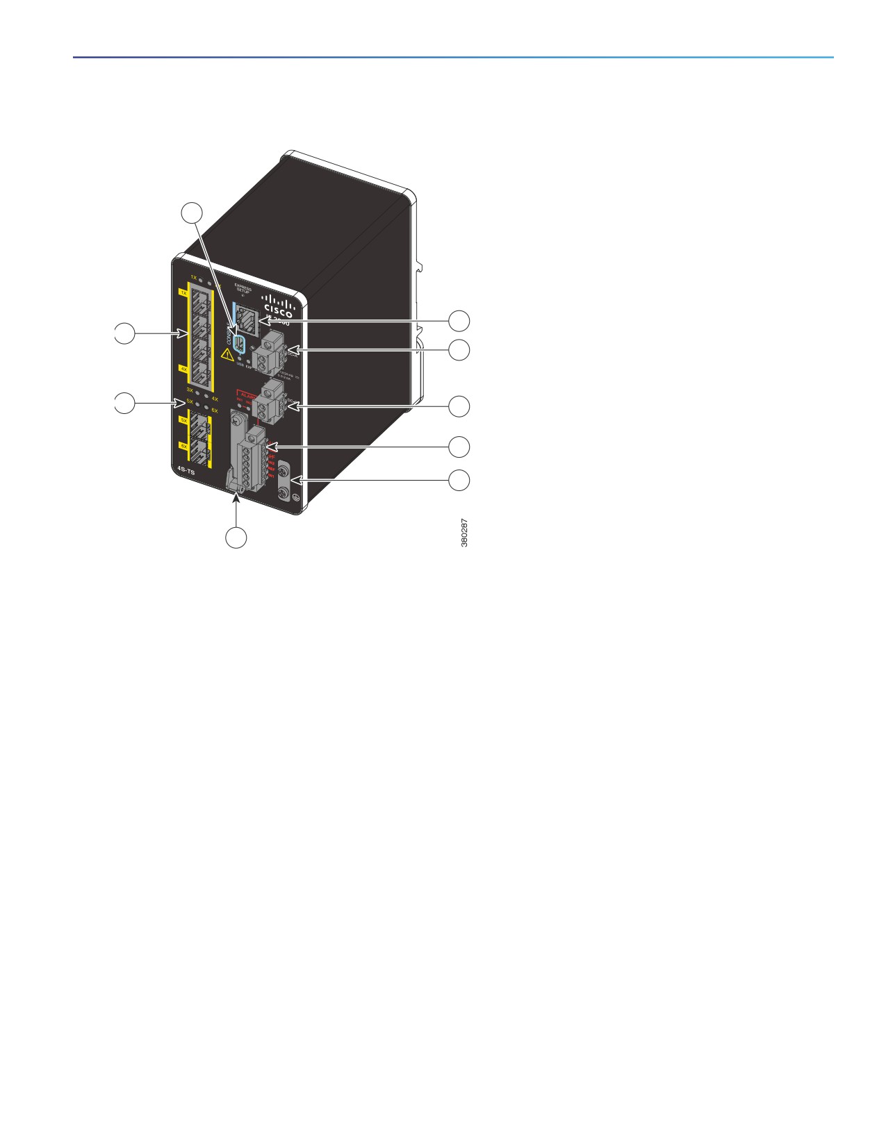
Figure 1
Cisco IE-2000-4S-TS-G-B Front Panel View
3
4
1
5
2
6
7
8
9
1
SFP module slots (downlink ports)
6
Power connector DC-B2
2
SFP module slots (uplink ports)
7
Alarm connector
3
USB mini-Type B (console) port1
8
Protective ground connection
4
RJ-45 console port
9
Flash memory card slot1
5
Power connector DC-A2
1 Use a screwdriver to remove the port cover and access the port.
2 Remove the plastic cover to access the power connector.
11
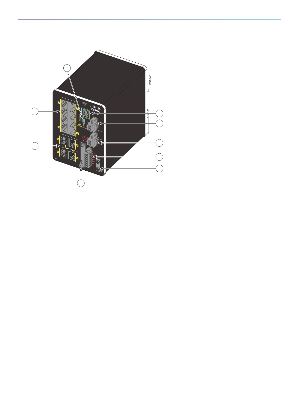
Figure 2
Cisco IE-2000-8TC-L Front Panel View
3
1
4
5
6
2
7
8
9
1
10/100 Ethernet ports (downlink ports)
6
Power connector DC-B2
2
Dual-purpose ports (uplink ports)
7
Alarm connector
3
USB mini-Type B (console) port1
8
Protective ground connection
4
RJ-45 console port
9
Flash memory card slot1
5
Power connector DC-A2
1 Use a screwdriver to remove the port cover and access the port.
2 Remove the plastic cover to access the power connector.
12
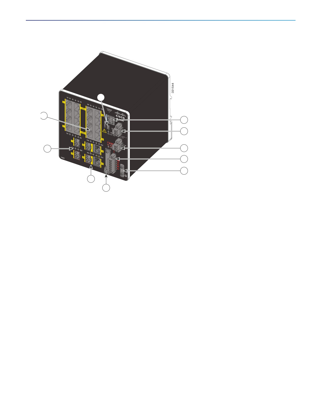
Figure 3
Cisco IE-2000-16TC-L Front Panel View
3
1
4
5
10
6
7
8
2
9
1
10/100 Ethernet ports (downlink ports)
6
Power connector DC-B2
2
Dual-purpose ports (uplink ports)
7
Alarm connector
3
USB mini-Type B (console) port1
8
Protective ground connection
4
RJ-45 console port
9
Flash memory card slot1
5
Power connector DC-A2
10
SFP module slots (uplink ports)
1 Use a screwdriver to remove the port cover and access the port.
2 Remove the plastic cover to access the power connector.
13
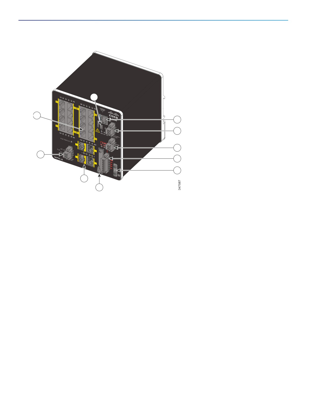
Figure 4
Cisco IE-2000-16PTC-G-E Front Panel View
3
1
4
5
6
10
7
8
2
9
1
10/100 Ethernet ports (downlink ports)
6
Power connector DC-B2
2
Dual-purpose ports (uplink ports)
7
Alarm connector
3
USB mini-Type B (console) port1
8
Protective ground connection
4
RJ-45 console port
9
Flash memory card slot1
5
Power connector DC-A2
10
PoE power connector
1 Use a screwdriver to remove the port cover and access the port.
2 Remove the plastic cover to access the power connector.
Ports and Slots
10/100BASE-T Downlink Ports, page 15
10/100BASE-T Uplink Ports, page 15
10/100/1000BASE-T Uplink Ports, page 15
100 Mb/s SFP Module Downlink Slots, page 15
100/1000 Mb/s SFP Module Uplink Slots, page 15
Dual-Purpose Fast Ethernet Uplink Ports, page 15
Dual-Purpose Gigabit Ethernet Uplink Ports, page 16
Power over Ethernet Ports, page 16
Management Ports, page 16
14
10/100BASE-T Downlink Ports
You can set the 10/100BASE-T downlink ports to operate at 10 or 100 Mb/s in full-duplex or half-duplex mode. You can
also set these ports for speed and duplex autonegotiation in compliance with IEEE 802.3ab. (The default setting is
autonegotiate.) When set for autonegotiation, the port senses the speed and duplex settings of the attached device and
advertises its own capabilities. If the connected device also supports autonegotiation, the switch port negotiates the best
connection (that is, the fastest line speed that both devices support, and full-duplex transmission if the attached device
supports it) and configures itself accordingly. In all cases, the attached device must be within 328 feet (100 meters).
100BASE-TX traffic requires CAT5 cable. 10BASE-T traffic can use Category 3 or Category 4 cables.
When connecting the switch to workstations, servers, routers, and Cisco IP phones, make sure that the cable is a
straight-through cable.
You can use the mdix auto interface configuration command in the command-line interface (CLI) to enable the automatic
medium-dependent interface crossover (auto-MDIX) feature. When the auto-MDIX feature is enabled, the switch detects
the required cable type for copper Ethernet connections and configures the interfaces accordingly. For configuration
information for this feature, see the switch software configuration guide or the switch command reference.
10/100BASE-T Uplink Ports
The IEEE 802.3u 10/100BASE-T uplink ports provide full-duplex 10, 100 Mb/s connectivity over CAT5 unshielded
twisted pair (UTP) copper cabling. The default setting is autonegotiate. The cable can be up to 100 m (0.1 km) in length.
10/100/1000BASE-T Uplink Ports
The IEEE 802.3u 10/100/1000BASE-T uplink ports provide full-duplex 10, 100 or 1000 Mb/s connectivity over CAT5
unshielded twisted pair (UTP) copper cabling. The default setting is autonegotiate. The cable can be up to 100 m
(0.1 km) in length.
100 Mb/s SFP Module Downlink Slots
The IEEE 802.3u 100 Mb/s SFP module downlink slots provide full-duplex 100 Mb/s connectivity over multi-mode (MM)
fiber cables or single-mode (SM) fiber cables. These ports use a SFP fiber-optic transceiver module that accepts a dual
local connector (LC). Check the SFP Module Cables, page 90 for the cable type and length.
100/1000 Mb/s SFP Module Uplink Slots
The IEEE 802.3u 100 Mb/s SFP module uplink slots provide full-duplex 100 or 1000 Mb/s connectivity over multi-mode
fiber (MMF) or single-mode fiber (SMF) cables, or CAT5 (or later) cables. These ports use a SFP fiber-optic transceiver
module that accepts a dual LC connector. See SFP Module Cables, page 90 for cable type and length.
10/100/1000BASE-T Copper SFP Module Uplink Slots
The IEEE 802.3 1000BASE-T copper SFP module slots provide full-duplex 1000Base-T connectivity over copper wire.
These ports use a copper SFP transceiver module that accepts an RJ-45 connector. See SFP Module Cables, page 90
for cable type and length.
Dual-Purpose Fast Ethernet Uplink Ports
You can configure the dual-purpose Fast Ethernet uplink ports on the switch as either 10/100BASE-T ports or as 100
Mb/s SFP-module ports. You can set the 10/100 ports to autonegotiate, or you can configure them as fixed 10 or 100
Mb/s ports.
15
By default, the switch selects the medium for each dual-purpose port (10/100BASE-T or SFP). When a link is achieved
on one media type, the switch disables the other media type until the active link goes down. If links are active on both
media, the SFP-module port has priority, but you can use the media-type interface configuration command to manually
designate the port as an RJ-45 port or an SFP port.
You can configure the speed and duplex settings consistent with the selected media type. For information on configuring
interfaces, see the switch software configuration guide.
Dual-Purpose Gigabit Ethernet Uplink Ports
You can configure the dual-purpose Gigabit Ethernet uplink ports on the switch as either 10/1001000BASE-T ports or
as 100/1000 Mb/s SFP-module ports. You can set the 10/100/1000BASE-T ports to autonegotiate, or you can configure
them as fixed 10, 100, or 1000 Mb/s (Gigabit) Ethernet ports.
By default, the switch selects the medium for each dual-purpose port (10/100/1000BASE-T or SFP). When a link is
achieved on one media type, the switch disables the other media type until the active link goes down. If links are active
on both media, the SFP-module port has priority, but you can use the media-type interface configuration command to
manually designate the port as an RJ-45 port or an SFP port.
You can configure the speed and duplex settings consistent with the selected media type. For information on configuring
interfaces, see the switch software configuration guide.
Power over Ethernet Ports
On certain models of the IE 2000 switch, four of the 10/100BASE-T ports are available as PoE ports. The four ports can
operate as PoE (IEEE 802.3af) ports or can be configured to operate as PoE+ (IEEE 802.at) ports. Each PoE port requires
15.4 Watts of power while PoE+ requires 30 Watts. A 54VDC /1.2A power source (65W) can support 4 PoE ports or 2
PoE+ ports. A 170W power source is needed to power 4 PoE+ ports.
Cable lengths of up to 328 ft (100 m) are supported.
Management Ports
You can connect the switch to a PC running Microsoft Windows or to a terminal server through either the RJ-45 console
port or the USB mini-Type B console port, also referred to as the USB-mini console port. These ports use the following
connectors:
RJ-45 console port uses an RJ-45-to-DB-9 female cable.
USB-mini console port (5-pin connector) uses a USB Type A-to-5-pin mini-Type B cable.
The USB-mini console interface speeds are the same as the RJ-45 console interface speeds.
To use the USB-mini console port, you must install the Cisco Windows USB device driver on the device that is connected
to the USB-mini console port and that is running Microsoft Windows.
Note: For information about downloading the Cisco USB device driver, see Installing the Cisco Microsoft Windows XP,
2000, Vista, 7, 8, and 10 USB Device Driver, page 105.
With the Cisco Windows USB device driver, connecting and disconnecting the USB cable from the console port does not
affect Windows HyperTerminal operations. Mac OS X or Linux require no special drivers.
Note: The 5-pin mini-Type B connectors resemble the 4-pin mini-Type B connectors, but they are not compatible. Use
only the 5-pin mini-Type B. See Figure 5 on page 17.
16
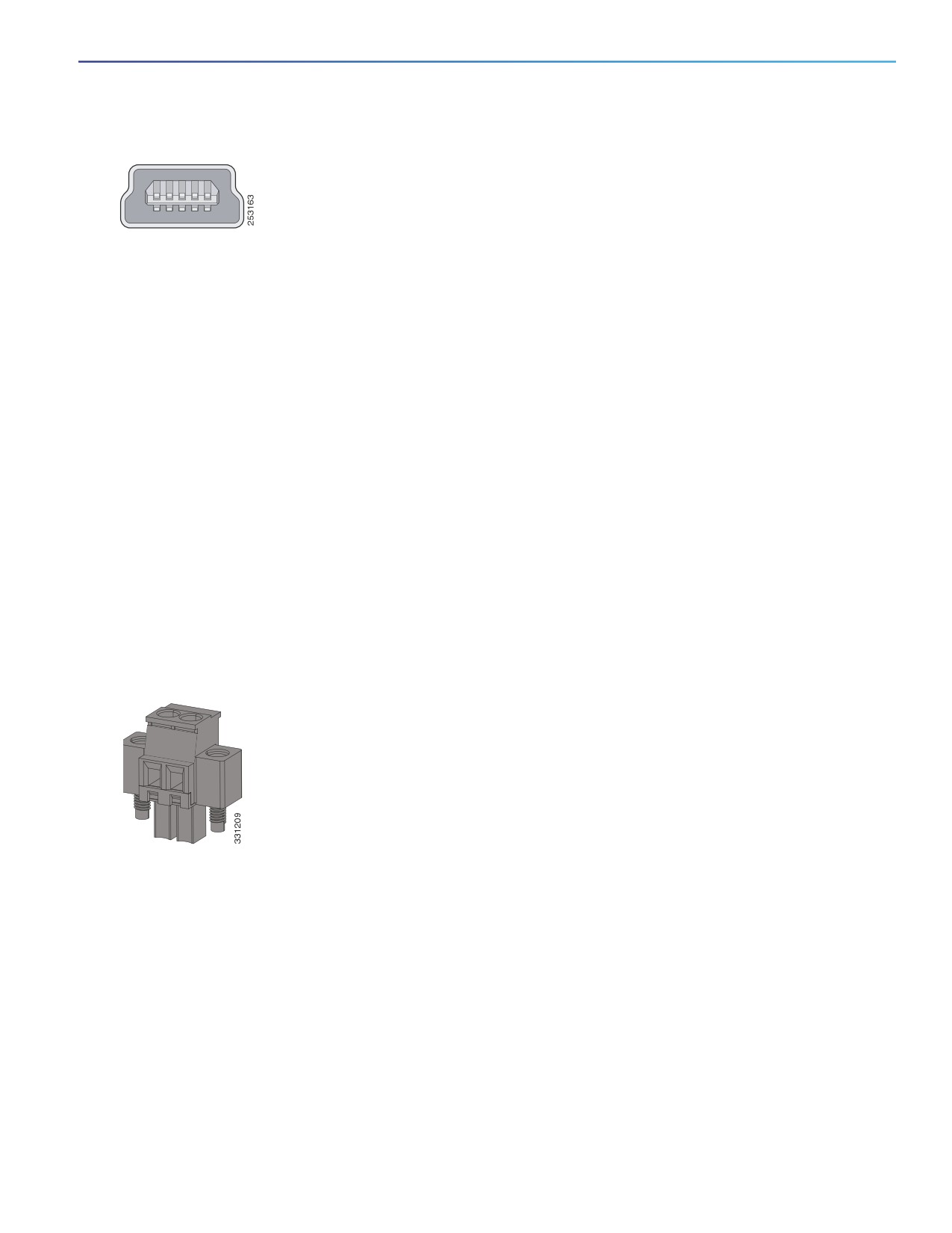
Figure 5
USB Mini-Type B Port
The configurable inactivity timeout reactivates the RJ-45 console port if the USB-mini console port is activated, but no
input activity occurs for a specified time period. When the USB-mini console port deactivates due to a timeout, you can
restore its operation by disconnecting and reconnecting the USB cable. For information on using the CLI to configure the
USB-mini console interface, see the switch software guide.
Power Connectors
DC Power Connector, page 17
PoE Power Connector, page 17
DC Power Connector
You connect the DC power to the switch through the front panel connectors. The switch has a dual-feed DC power
supply; two connectors provide primary and secondary DC power (DC-A and DC-B). The DC power connectors are near
the top right of the front panel (see Figure 2 on page 12). Each power connector has an LED status indicator.
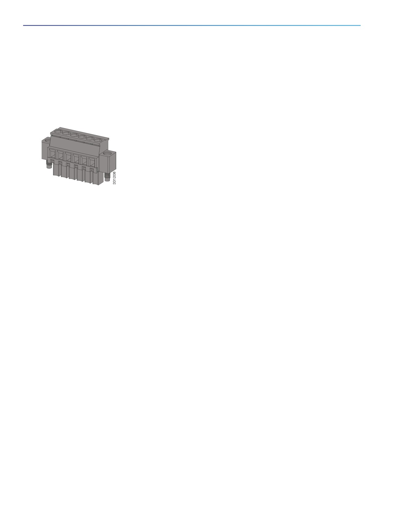
The switch power connectors are attached to the switch chassis. Each power connector has screw terminals for
terminating the DC power (see Figure 6 on page 17). All connectors are attached to the switch front panel with the
provided captive screws.
The power connector labeling is on the panel. The positive DC power connection is labeled “+”, and the return
connection is labeled “-”.
Figure 6
Power Connector
The switch can operate with a single power source or with dual power sources. When both power sources are
operational, the switch draws power from the DC source with the higher voltage. If one of the two power sources fail,
the other continues to power the switch.
In systems configured with the redundant power option, connect each of the two power supplies to separate
independent power sources. If you fail to do this, your system might be susceptible to total power failure due to a fault
in the external wiring or a tripped circuit breaker.
PoE Power Connector
The IE 2000 switch models with PoE capability (IE-2000-16PTC-G-E, IE-2000-16PTC-G-L, and IE-2000-16PTC-G-NX)
are equipped with an additional DC input terminal block. This DC terminal block allows the connection of a second power
supply (see Power over Ethernet Ports, page 16), or a second input from site source DC power to operate the PoE ports.
The PoE terminal block accepts 48 VDC or 54 VDC at 2.5 A.
17
Alarm Connector
You connect the alarm signals to the switch through the alarm connector. The switch supports two alarm inputs and one
alarm output relay. The alarm connector is on the bottom right of the front panel. See Figure 3 on page 13.
The alarm connector provides six alarm wire connections. The connector is attached to the switch front panel with the
provided captive screws.
Figure 7
Alarm Connector
Both alarm input circuits can sense if the alarm input is open or closed. The alarm inputs can be activated for
environmental, power supply, and port status alarm conditions. From the CLI, you can configure each alarm input as an
open or closed contact.
The alarm output circuit is a relay with a normally open and a normally closed contact. The switch is configured to detect
faults that are used to energize the relay coil and change the state on both of the relay contacts: normally open contacts
close, and normally closed contacts open. The alarm output relay can be used to control an external alarm device, such
as a bell or a light.
See the switch software configuration guide for instructions on configuring the alarm relays.
For more information about the alarm connector, see Cable and Connectors, page 87.
18

SFP Modules
The switch Ethernet SFP modules provide connections to other devices. These field-replaceable transceiver modules
provide the uplink interfaces. LC connectors provide fiber-optic connections; RJ-45 connectors for copper connections.
You can use any combination of the supported SFP modules listed in Table 2 on page 19.
Table 2
SFP Module Maximum Operating Temperature by Model
SFP Module
Model
Rugged and Industrial SFPs
GLC-SX-MM-RGD
-40 to 185°F (-40 to 85°C)
GLC-LX-SM-RGD
GLC-FE-100LX-RGD
GLC-FE-100FX-RGD
GLC-FE-T-I
GLC-ZX-SM-RGD
GLC-BX40-D-I with digital optical monitoring (DOM) support
GLC-BX40-DA-I with DOM support
GLC-BX80-D-I with DOM support
GLC-BX40-U-I with DOM support
GLC-BX80-U-I with DOM support
Commercial SFPs
GLC-BX-D with DOM support
32 to 158°F (0 to 70°C)
GLC-BX-U with DOM support
GLC-FE-100LX
GLC-FE-100BX-D
GLC-FE-100BX-U
GLC-FE-100FX
GLC-FE-100EX
GLC-FE-100ZX
GLC-T
CWDM with DOM support
DWDM with DOM support
19
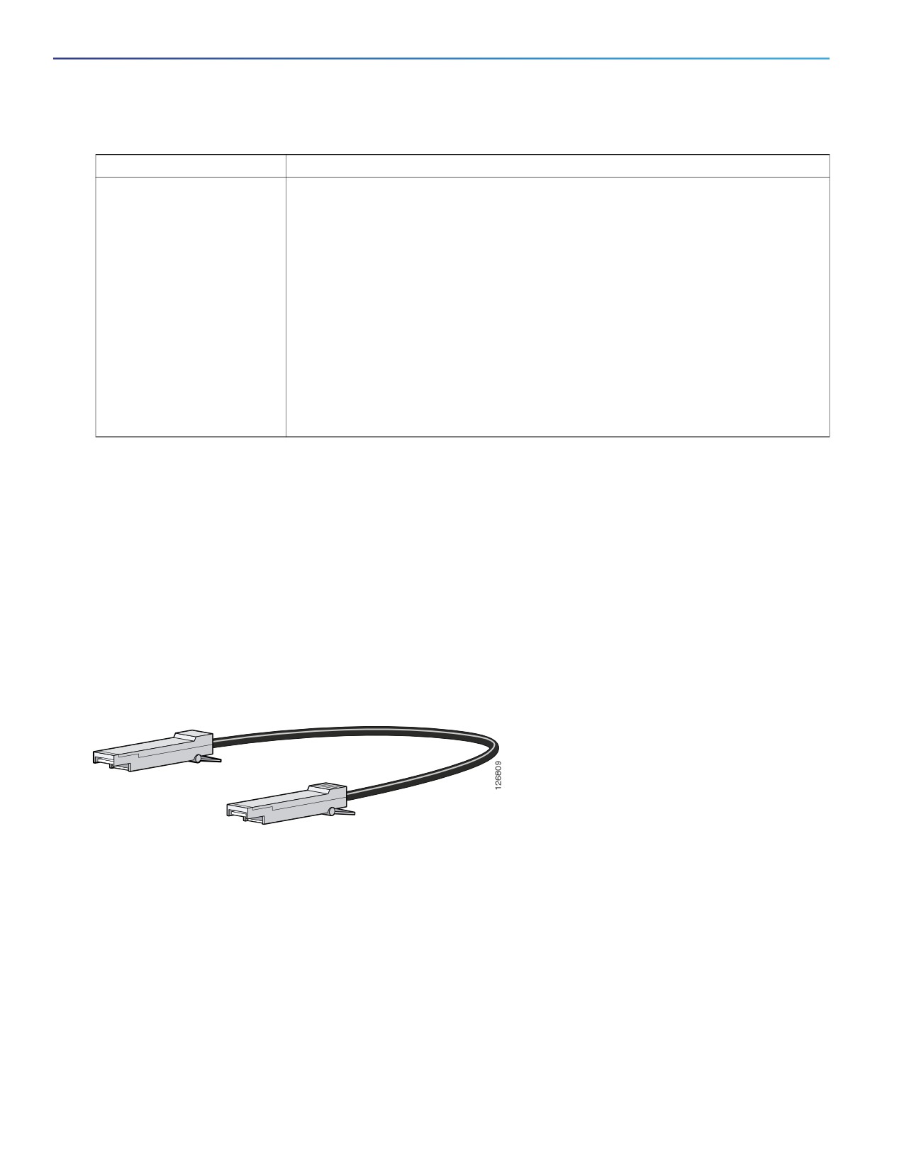
Table 2
SFP Module Maximum Operating Temperature by Model (continued)
SFP Module
Model
Extended temperature SFPs
SFP-GE-L with DOM support
23 to 185°F (-5°C to 85°C)
SFP-GE-S with DOM support
SFP-GE-T
SFP-GE-Z with DOM support
GLC-LH-SMD with DOM support
GLC-EX-SMD with DOM support
GLC-SX-MMD with DOM support
GLC-TE
GLC-ZX-SMD with DOM support
For minimum software requirements, refer to the Release Notes for your platform.
For an up-to-date list of supported SFP models for Cisco Industrial Ethernet switches, see
38176
For installation instructions, see your SFP module documentation and the Installing and Removing SFP Modules, page 66.
For cable specifications, see SFP Module Cables, page 90.
SFP Module Patch Cable
The switch uses an SFP-module patch cable, a 0.5-meter, copper, passive cable with SFP module connectors at each
end (see Figure 8 on page 20). The patch cable connects two switches in a cascaded configuration.
Figure 8
SFP-Module Patch Cable
See Installing and Removing SFP Modules, page 66 for information about using the SFP module patch cable.
You can order this cable (part number CAB-SFP-50CM=).
LEDs
You can use the LEDs to monitor the switch status, activity, and performance. Figure 9 on page 21 and Table 9 on
page -24 show the front panel LEDs.
20
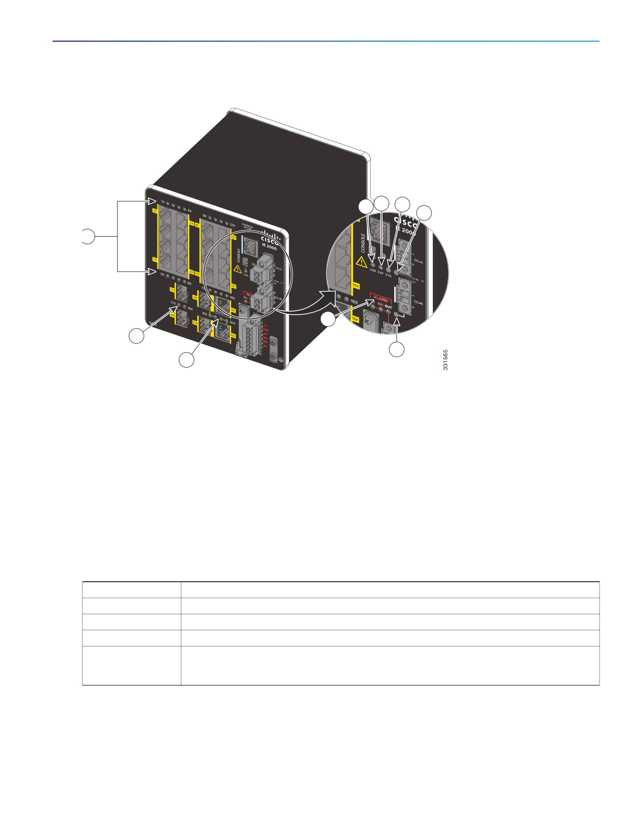
Figure 9
LEDs on the Cisco IE 2000 Switch
3
4
2
5
7
1
8
6
9
1
Alarm LEDs
6
Power connector DC-B LED
2
USB mini-Type B (console) port LED
7
10/100BASE-T downlink port LEDs
3
Express Setup LED
8
SFP module slot LEDs
4
System LED
9
Dual-purpose uplink port LEDs
5
Power connector DC-A LED
Note: On IE 2000 switches with PoE support, the two SFP ports and the associated LEDs are replaced by a PoE DC-input
terminal block and a PoE LED. For more information, see PoE Status LED, page 24.
Express Setup LED
The Express Setup LED displays the express setup mode for the initial configuration.
Table 3
Express Setup LED
Color
Setup Status
Off (dark)
Switch is configured as a managed switch.
Solid green
Switch is operating normally.
Blinking green
Switch is in initial setup, in recovery, or initial setup is incomplete.
Solid red
Switch failed to start initial setup or recovery because there is no available switch port to which
to connect the management station. Disconnect a device from a switch port, and then press
the Express Setup button.
21

System LED
The System LED shows whether the system is receiving power and is functioning properly.
Table 4
System LED
Color
System Status
Off
System is not powered on.
Blinking green
Boot fast is in progress.
Green
System is operating normally.
Red
Switch is not functioning properly.
USB-Mini Console LED
The USB-mini console LED shows which console port is in use. See Figure 9 on page 21 for the LED location. If you
connect a cable to a console port, the switch automatically uses that port for console communication. If you connect two
console cables, the USB-mini console port has priority.
Table 5
USB-Mini Console LED
Color
Description
Green
USB-mini console port is active.
RJ-45 console port LED is not active.
Off
Port is not active.
RJ-45 console port is active.
Alarm LEDs
Table 6 on page -22 and Table 7 on page -22 list the alarm LED colors and their meanings.
Table 6
Alarm OUT LED
Color
System Status
Off
Alarm OUT is not configured, or the switch is off.
Green
Alarm OUT is configured, no alarm detected.
Blinking red
Switch has detected a major alarm.
Red
Switch has detected a minor alarm.
Table 7
Alarm IN1 and IN2 Status LEDs
Color
System Status
Off
Alarm IN1 or IN2 not configured.
Green
Alarm IN1 or IN2 configured, no alarm detected.
Blinking red
Major alarm detected.
Red
Minor alarm detected.
22

Power Status LEDs
The switch can operate with one or two DC power sources. Each DC input has an associated LED that shows the status
of the corresponding DC input. If power is present on the circuit, the LED is green. If power is not present, the LED color
depends on the alarm configuration. If alarms are configured, the LED is red when power is not present; otherwise, the
LED is off.
If the switch has dual power sources, the switch draws power from the power source with the higher voltage. If one of
the DC sources fails, the alternate DC source powers the switch, and the corresponding power status LED is green. The
power status for the failed DC source is either off or red, depending on the alarm configuration.
Table 8
Power Status LEDs
Color
System Status
Green
Power is present on the associated circuit, system is operating normally.
Off
Power is not present on the circuit, or the system is not powered up.
Red
Power is not present on the associated circuit, and the power supply alarm is
configured.
The Power A and Power B LEDs show that power is not present on the switch if the power input drops below the low
valid level. The power status LEDs only show that power is present if the voltage at the switch input exceeds the valid
level.
For information about the power LED colors during the boot fast sequence, see Verifying Switch Operation, page 72.
Port Status LEDs
Each port and SFP uplink slot has a status LED, as shown in Figure 9 on page 21 and Figure 10 on page 24.
Table 9
Port Status LEDs
Color
System Status
Off
No link.
Solid green
Link present.
Blinking green
Activity. Port is sending or receiving data.
Alternating green-amber
Link fault. Error frames can affect connectivity, and errors such as excessive collisions,
CRC errors, and alignment and jabber errors are monitored for a link-fault indication.
Solid amber
Port is not forwarding. The port was disabled by management, an address violation, or STP.
Note: After a port is reconfigured, the port LED can remain amber for up to 30 seconds
while STP checks the switch for possible loops.
Dual-Purpose Port LEDs
Figure 10 on page 24 shows the LEDs on a dual-purpose port. The LEDs show how the port is being used (Ethernet or
SFP module). The LED colors have the same meanings as for the Port Status LEDs, page 23.
23
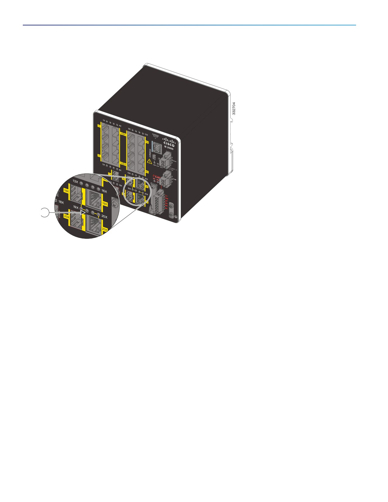
Figure 10
Dual-Purpose Port LEDs
1
1
Dual-purpose port LEDs
PoE Status LED
The PoE STATUS LED is located on the front panel of the IE 2000 switch models that are equipped with PoE ports.The
LED displays the functionality and status of the PoE ports.
24

Table 10
PoE Status LED
Color
PoE Status
Off
PoE is off. If the powered device is receiving power from a non-PoE power source, the
port LED is off even if the powered device is connected to the switch port.
Green
PoE is on. The port LED is green only when the PoE port is providing power.
Alternating green and amber
PoE is denied because providing power to the powered device will exceed the switch
power capacity.
Flashing amber
PoE is off due to a fault.
Caution: Non-compliant cabling or powered devices can cause a PoE port fault. Use
only standard-compliant cabling to connect Cisco pre-standard IP Phones and
wireless access points or IEEE 802.3af-compliant devices. You must remove any cable
or device that causes a PoE fault.
Amber
PoE for the port is disabled. (PoE is enabled by default.)
Flash Memory Card
The switch supports a flash memory card that makes it possible to replace a failed switch without reconfiguring the new
switch. The slot for the flash memory card is on the front of the switch. The flash card is hot swappable and can be
accessed on the front panel. A cover protects the flash card and holds the card firmly in place. The cover is hinged and
closed with a captive screw. This prevents the card from coming loose and protects against shock and vibration.
For more information on inserting and removing the flash memory card, see Installing or Removing the Flash Memory
Card (Optional), page 33.
Note: The replacement SD card part number is SD-IE-1GB.
Rear Panel
The rear panel of the switch has a latch for installation on a DIN rail. See Figure 11 on page 26. The latch is spring-loaded
to move down to position the switch over a DIN rail and return to the original position to secure the switch to a DIN rail.
25
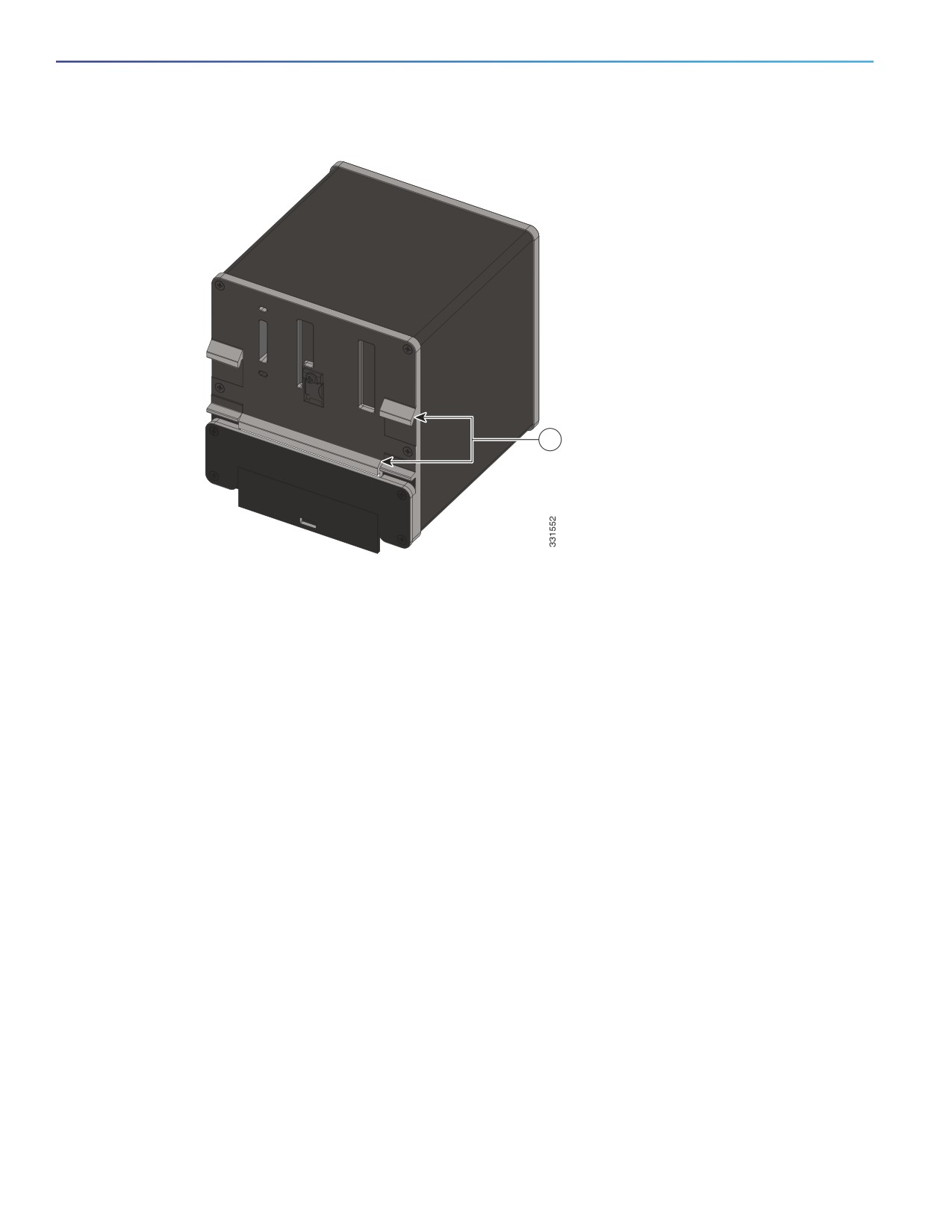
Figure 11
Cisco IE 2000 Switch Rear Panel
1
1
Latch
Management Options
The switch supports these management options:
Cisco Network Assistant
Cisco Network Assistant is a PC-based network management GUI application optimized for LANs of small- and
medium-sized businesses. Using the GUI, you can configure and manage switch clusters or standalone switches.
Cisco Network Assistant is available at no cost and can be downloaded from this URL:
For information on starting the Cisco Network Assistant application, see the Getting Started with Cisco Network
Assistant guide on Cisco.com.
Device Manager
You can use Device Manager, which is in the switch memory, to manage individual and standalone switches. This
web interface offers quick configuration and monitoring. You can access Device Manager from anywhere in your
network through a web browser. For more information, see Running Express Setup, page 97 and the Device Manager
online help.
Cisco IOS CLI
The switch CLI is based on Cisco IOS software and is enhanced to support desktop-switching features. You can fully
configure and monitor the switch. You can access the CLI either by connecting your management station directly to
the switch management port, or a console port, or by using Telnet from a remote management station. See the
switch command reference on Cisco.com for more information.
26
Cisco Prime LAN Management Solution 4.2
ms42sdt.html#Cisco IE 2000 Series Switches
SNMP network management
You can manage switches from a SNMP-compatible management station that is running platforms such as HP
OpenView or SunNet Manager. The switch supports a comprehensive set of Management Information Base (MIB)
extensions and four Remote Monitoring (RMON) groups. See the switch software configuration guide on Cisco.com
and the documentation that came with your SNMP application for more information.
Common Industrial Protocol
The Common Industrial Protocol (CIP) management objects are supported. The Cisco IE 2000 can be managed by
CIP-based management tools, allowing the user to manage an entire industrial automation system with one tool.
PROFINET TCP/IP and RT
This switch supports PROFINET TCP/IP and RT and can be managed by Siemens' automation software such as
STEP 7.
Network Configurations
See the switch software configuration guide on Cisco.com for network configuration concepts and examples of using
the switch to create dedicated network segments and interconnecting the segments through Gigabit Ethernet
connections.
27
28
Switch Installation
This chapter describes how to install your switch, verify the boot fast, and connect the switch to other devices. It also
includes information specifically for installations in hazardous environments.
Read these topics, and perform the procedures in this order:
Preparing for Installation, page 29
Installing or Removing the Flash Memory Card (Optional), page 33
Connecting to a Console Port, page 35
Connecting to Power, page 39
Installing the Switch, page 55
Connecting Alarm Circuits, page 60
Connecting Destination Ports, page 64
Verifying Switch Operation, page 72
Where to Go Next, page 72
Preparing for Installation
This section provides information about these topics:
Warnings, page 29
Additional Information for Installation in a Hazardous Environment, page
30
Installation Guidelines, page 32
Verifying Package Contents, page 33
Warnings
These warnings are translated into several languages in the Regulatory Compliance and Safety Information for this
switch.
Warning: Before working on equipment that is connected to power lines, remove jewelry (including rings,
necklaces, and watches). Metal objects will heat up when connected to power and ground and can cause serious
burns or weld the metal object to the terminals. Statement 43
Warning: Do not work on the system or connect or disconnect cables during periods of lightning activity. Statement
1001
Warning: Before performing any of the following procedures, ensure that power is removed from the DC circuit.
Statement 1003
Warning: Read the installation instructions before you connect the system to its power source. Statement 1004
29
Warning: This unit is intended for installation in restricted access areas. A restricted access area can be accessed
only through the use of a special tool, lock and key, or other means of security. Statement 1017
Warning: This equipment must be grounded. Never defeat the ground conductor or operate the equipment in the
absence of a suitably installed ground conductor. Contact the appropriate electrical inspection authority or an
electrician if you are uncertain that suitable grounding is available. Statement 1024
Warning: This unit might have more than one power supply connection. All connections must be removed to
de-energize the unit. Statement 1028
Warning: Only trained and qualified personnel should be allowed to install, replace, or service this equipment.
Statement 1030
Warning: Ultimate disposal of this product should be handled according to all national laws and regulations.
Statement 1040
Warning: For connections outside the building where the equipment is installed, the following ports must be
connected through an approved network termination unit with integral circuit protection. 10/100/1000 Ethernet
Statement 1044
Warning: To prevent the system from overheating, do not operate it in an area that exceeds the maximum
recommended ambient temperature of: 140°F (60°C) Statement 1047
Warning: Installation of the equipment must comply with local and national electrical codes. Statement 1074
Caution: Airflow around the switch must be unrestricted. To prevent the switch from overheating, there must be the
following minimum clearances:
Top and bottom: 2.0 in. (50.8 mm)
Sides: 2.0 in. (50.8 mm)
Front: 2.0 in. (50.8 mm)
Additional Information for Installation in a Hazardous Environment
Hazardous Area Installation Warnings
Warning: Exposure to some chemicals could degrade the sealing properties of materials used in the sealed relay
device. Statement 381
Warning: Failure to securely tighten the captive screws can result in an electrical arc if the connector is accidentally
removed. Statement 397
Warning: When you connect or disconnect the power and/or alarm connector with power applied, an electrical arc
can occur. This could cause an explosion in hazardous area installations. Be sure that all power is removed from the
switch and any other circuits. Be sure that power cannot be accidentally turned on or verify that the area is
nonhazardous before proceeding. Statement 1058
Warning: In switch installations in a hazardous location, the DC power source could be located away from the
vicinity of the switch. Before performing any of the following procedures, locate the DC circuit to ensure that the
power is removed and cannot be turned on accidentally, or verify that the area is nonhazardous before proceeding.
Statement 1059
Warning: This equipment is supplied as “open type” equipment. It must be mounted within an enclosure that is
suitably designed for those specific environmental conditions that will be present and appropriately designed to
prevent personal injury resulting from accessibility to live parts. The interior of the enclosure must be accessible
only by the use of a tool. The enclosure must meet IP 54 or NEMA type 4 minimum enclosure rating standards.
Statement 1063
30
Warning: When used in a Class I, Division 2, hazardous location, this equipment must be mounted in a suitable
enclosure with proper wiring method, for all power, input and output wiring, that complies with the governing
electrical codes and in accordance with the authority having jurisdiction over Class I, Division 2 installations.
Statement 1066
Warning: Use twisted-pair supply wires suitable for 86°F (30°C) above surrounding ambient temperature outside
the enclosure. Statement 1067
Warning: This equipment is intended for use in a Pollution Degree 2 industrial environment, in overvoltage Category
II applications (as defined in IEC publication 60664-1), and at altitudes up to 2000 meters without derating.
Statement 1068
Warning: Do not connect or disconnect cables to the ports while power is applied to the switch or any device on
the network because an electrical arc can occur. This could cause an explosion in hazardous location installations.
Be sure that power is removed from the switch and cannot be accidentally be turned on, or verify that the area is
nonhazardous before proceeding. Statement 1070
Warning: If you connect or disconnect the console cable with power applied to the switch or any device on the
network, an electrical arc can occur. This could cause an explosion in hazardous location installations. Be sure that
power is removed or the area is nonhazardous before proceeding. Statement 1080
Warning: Explosion Hazard—Do not connect or disconnect wiring while the field-side power is on; an electrical arc
can occur. This could cause an explosion in hazardous location installations. Be sure that power is removed or that
the area is nonhazardous before proceeding. Statement 1081
Warning: Explosion Hazard—The area must be known to be nonhazardous before installing, servicing, or replacing
the unit. Statement 1082
Warning: Explosion Hazard—Substitution of components may impair suitability for Class I, Division 2/Zone 2.
Statement 1083
Warning: Do not insert and remove SFP modules while power is on; an electrical arc can occur. This could cause an
explosion in hazardous location installations. Be sure that power is removed or the area is nonhazardous before
proceeding. Statement 1087
Caution: This equipment is only suitable for use in Class I, Division 2, Groups A, B, C, D, or nonhazardous locations.
North American Hazardous Location Approval
The following information applies when operating this equipment in hazardous locations:
English:
Products marked "Class I, Div 2, GP A, B, C, D" are suitable for use in Class I Division 2 Groups A,
B, C, D, Hazardous Locations and nonhazardous locations only. Each product is supplied with
markings on the rating nameplate indicating the hazardous location temperature code. When
combining products within a system, the most adverse temperature code (lowest "T" number)
may be used to help determine the overall temperature code of the system. Combinations of
equipment in your system are subject to investigation by the local Authority Having Jurisdiction at
the time of installation.
Français:
Informations sur l'utilisation de cet équipement en environnements dangereux:
Les produits marqués "Class I, Div 2, GP A, B, C, D" ne conviennent qu'à une utilisation en
environnements de Classe I Division 2 Groupes A, B, C, D dangereux et non dangereux. Chaque
produit est livré avec des marquages sur sa plaque d'identification qui indiquent le code de
température pour les environnements dangereux. Lorsque plusieurs produits sont combinés dans
un système, le code de température le plus défavorable (code de température le plus faible) peut
être utilisé pour déterminer le code de température global du système. Les combinaisons
d'équipements dans le système sont sujettes à inspection par les autorités locales qualifiées au
moment de l'installation.
31
EMC Environmental Conditions for Products Installed in the European Union
This section applies to products to be installed in the European Union.
The equipment is intended to operate under the following environmental conditions with respect to EMC:
A separate defined location under the user’s control.
Earthing and bonding shall meet the requirements of ETS 300 253 or CCITT K27.
AC-power distribution shall be one of the following types, where applicable: TN-S and TN-C as defined in IEC
364-3.
In addition, if equipment is operated in a domestic environment, interference could occur.
Installation Guidelines
When determining where to place the switch, observe these guidelines.
Environment and Enclosure Guidelines
Review these environmental and enclosure guidelines before installation:
This equipment is intended for use in a Pollution Degree 2 industrial environment, in overvoltage Category II
applications (as defined in IEC publication 60664-1), at altitudes up to 9842 ft (3 km) without derating.
This equipment is considered Group 1, Class A industrial equipment, according to IEC/CISPR Publication 11. Without
appropriate precautions, there may be potential difficulties ensuring electromagnetic compatibility in other
environments due to conducted as well as radiated disturbance.
This equipment is supplied as open-type equipment. It must be mounted within an enclosure that is suitably
designed for those specific environmental conditions that will be present and appropriately designed to prevent
personal injury resulting from accessibility to live parts. The enclosure must have suitable flame-retardant properties
to prevent or minimize the spread of flame, complying with a flame-spread rating of 5VA, V2, V1, V0 (or equivalent)
if nonmetallic. The interior of the enclosure must be accessible only by the use of a tool. Subsequent sections of this
publication might contain additional information regarding specific enclosure-type ratings that are required to
comply with certain product safety certifications.
General Guidelines
Before installation, observe these general guidelines:
Caution: Proper ESD protection is required whenever you handle Cisco equipment. Installation and maintenance
personnel should be properly grounded by using ground straps to eliminate the risk of ESD damage to the switch.
Caution: Do not touch connectors or pins on component boards. Do not touch circuit components inside the switch.
When not in use, store the equipment in appropriate static-safe packaging.
If you are responsible for the application of safety-related programmable electronic systems (PES), you need to be
aware of the safety requirements in the application of the system and be trained in using the system.
Caution: The device is designed to mount on a DIN rail that conforms to Standard EN50022.
When determining where to place the switch, observe these guidelines:
Before installing the switch, first verify that the switch is operational by powering it on and observing boot fast. Follow
the procedures in Verifying Switch Operation, page 72.
For 10/100 ports and 10/100/1000 ports, the cable length from a switch to an attached device cannot exceed 328
feet (100 meters).
32
///////////////////////////////////////