Kawasaki Robot Controller E Series. Installation and Connection Manual (2017) - page 3
5. Arrangement of Robot Controller
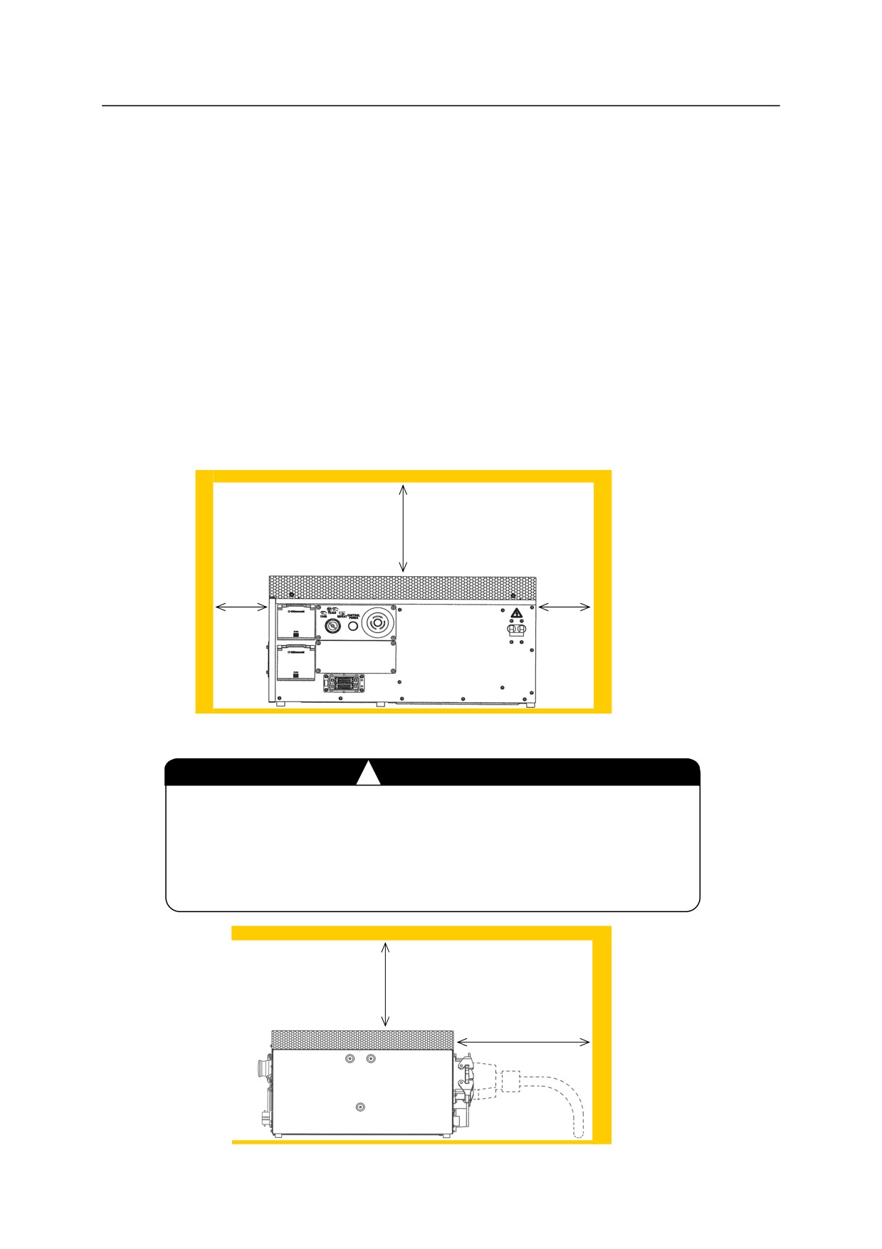
5.2 ARRANGEMENT OF E7X/E9X CONTROLLERS
Horizontal arrangement is the standard for E7x and E9x controllers. Follow the procedure
below to arrange the controllers. For the E9x controller with the enclosed structure, the ambient
temperature should be between 0-40 C.
1. Arrange the controller on a flat, horizontal floor. An object cannot be placed on the top
surface of E7x controller. When an object is placed on the top surface of E9x controller, the
mass should be 40 kg or less. It is possible to place an E9x controller on another E9x
controller as far as the mass goes. However, when an object is placed on the top surface of
E9x controller, it is necessary to remove the object once in maintenance.
2. Separate the controller right/left side from the wall by 100 mm or more.
3. Separate the controller top surface from the wall by 200 mm or more.
200 mm or more
100 mm
100 mm
or more
or more
4. Heat exchange fan is provided on the rear of the E7x controller.
!
CAUTION
Do not block the air inlet and exhaust ports when arranging the E7x
controller. For the E7x controller, separate the controller backside
from the wall by 300 mm or more, leaving enough space for the
separate harness to be bent.
200 mm or
more
E7x: 300 mm or more
E9x: 200 mm or more
76
5. Arrangement of Robot Controller
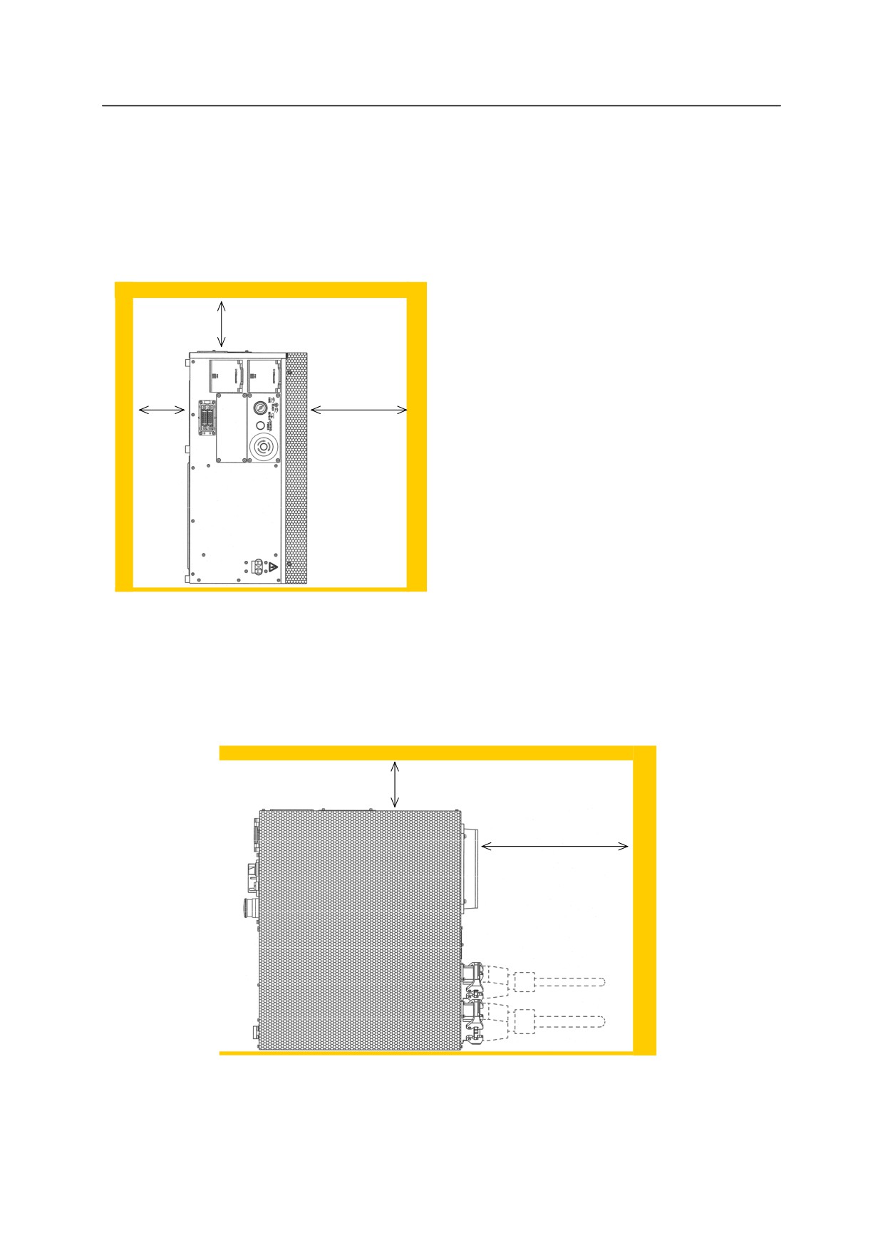
Follow the procedure below when arranging E7x/E9x controllers vertically. The ambient
temperature should be within 0-40 C when arranging the E7x controller vertically. For the
E9x controller, feet attached on the bottom of the controller can be reattached on the right side.
An object cannot be placed on the top surface of the controller when the controllers are placed
vertically.
1.
Arrange the controller on a horizontal
100 mm
floor. Arrange the controller with its
or more
controller power switch facing
downward.
2.
Separate the controller right side (top
surface when placing the controller
100 mm
200 mm
vertically) from the wall by 200 mm or
or more
or more
more.
3.
Separate the controller top/left side from
the wall by 100 mm or more.
4.
Separate the controller rear side from the
wall by 300 mm or more for E7x
controller and 200 mm for E9x
controller.
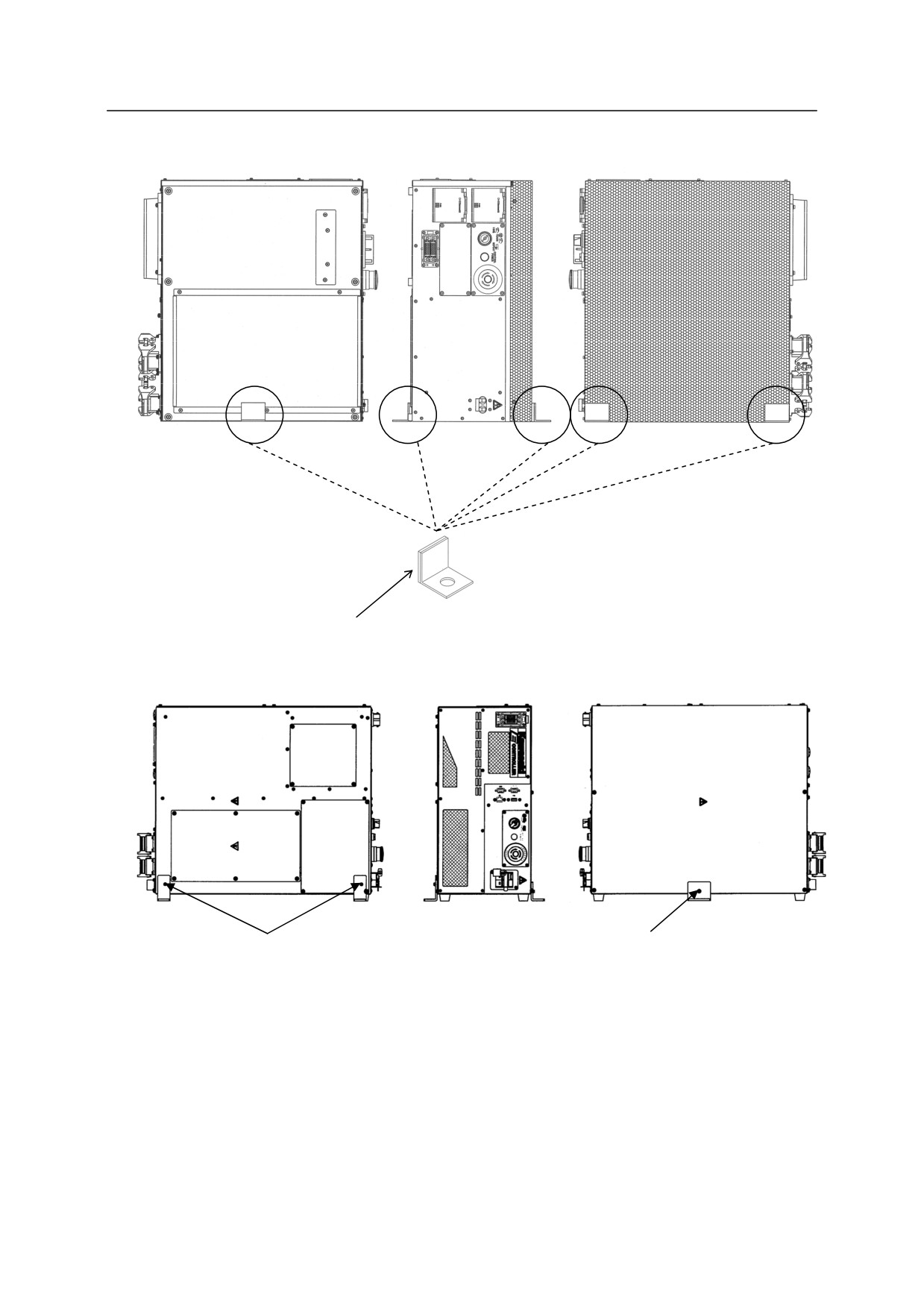
5.
If needed, make metal fittings as shown
in the figure on the next page to fix the
controller.
100 mm
or more
E7x: 300 mm or more
E9x: 200 mm or more
77
5. Arrangement of Robot Controller
E7x controller
Rubber lining
Metal fittings
E9x controller
䖩
Fixing bracket
Fixing bracket
Height from ground
Height from ground
plane to fixing hole:
plane to fixing hole:
approx. 25 mm
approx. 44 mm
Fixing screw: M4
Fixing screw: M4
NOTE: Replace foot rubbers together with fixing screws when the foot rubbers on the bottom are
attached on the right side. If the screw with 䖩 mark is too long, change it to the screw
whole length is 6 mm or less when changing the screw. Otherwise, internal parts may
be damaged.
78
6. Connection Instructions
6.0 CONNECTION INSTRUCTIONS
6.1 CONNECTION BETWEEN CONTROLLER AND ROBOT
!
WARNING
Do not connect the external power until connections between controller and robot
are complete. Accidents, such as electric shock may occur.
!
CAUTION
1. When connecting the harnesses, be sure to use the correct harnesses. Using an
incorrect harness, or forcing or misconnecting the harness may damage
connectors or cause a break in the electrical system.
2. Prevent people or equipment (forklift etc.) from stepping on or riding over the
signal and motor harness lines. Otherwise, the harness may become damaged or
the electrical system may break.
3. Even when the harnesses are long, do not bundle them winded or bended.
Bundling the harness causes the heat to build up in the harness, resulting in
over-heat and furthermore may cause fire.
4. Separate the harnesses from any nearby high voltage lines (min. 1 m apart). Do
not bundle or run the harnesses in parallel with other power lines. Otherwise,
the noise generated from power lines will cause malfunctions.
5. Separate the motor harness from the communication and sensor cables, and
distribute the lines so they are neither bundled nor running in parallel.
Moreover, connect the communication and sensor cables using shield mesh wire
that includes twisted pair lines and connect the mesh wire to an adequate FG
terminal. Otherwise, PWM noise radiated from the robot’s motor drive lines
may penetrate into various cables, such as communication cable and cause
communication errors.
6. Separate the welder secondary cable from the robot’s signal harness. Do not
wire them in the same duct.
7. The motor harness (power line) between the robot and controller will generate
PWM noise due to the PWM control driving the motors. This noise may cause
interference with signal lines. Prevent interference using these countermeasures:
(1) Separate the power and signal lines as much as possible.
(2) Use the shortest possible length for the power line.
(3) Avoid bundling, wiring in parallel the power and signal lines as much as
possible.
(4) Do not wire the power and signal line within the same duct/conduit.
(5) Set and secure a firm earth line connection for the controller.
79
6. Connection Instructions
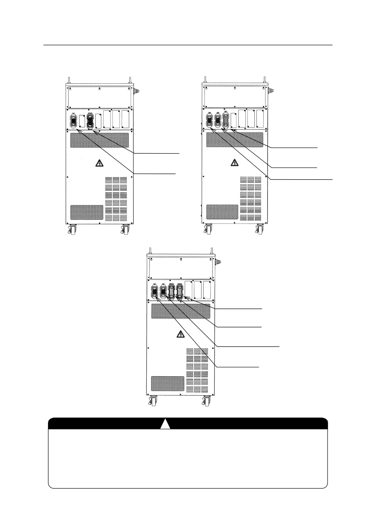
Connect the separate harnesses to their designated ports as shown below.
1. Controller side
Major axis motor
Motor harness
harness (X4)
(X4)
Wrist axis motor
Signal
harness (X5)
harness (X3)
Signal harness (X3)
E10 controller
E12/E13 controllers
Wrist axis motor
harness (X4-2)
Major axis motor
harness (X4-1)
Brake and JT7 motor
harness (X5)
Signal
harness (X3)
E14 controller
!
CAUTION
1. Fix each connector securely. The robot may malfunction if connectors loosen or
detach.
2. The harness should drop straight down from the connector. Because connectors
are located at the upper part of controller, the controller might topple over if the
connected harnesses are pulled to the controller side or to the rear direction.
80
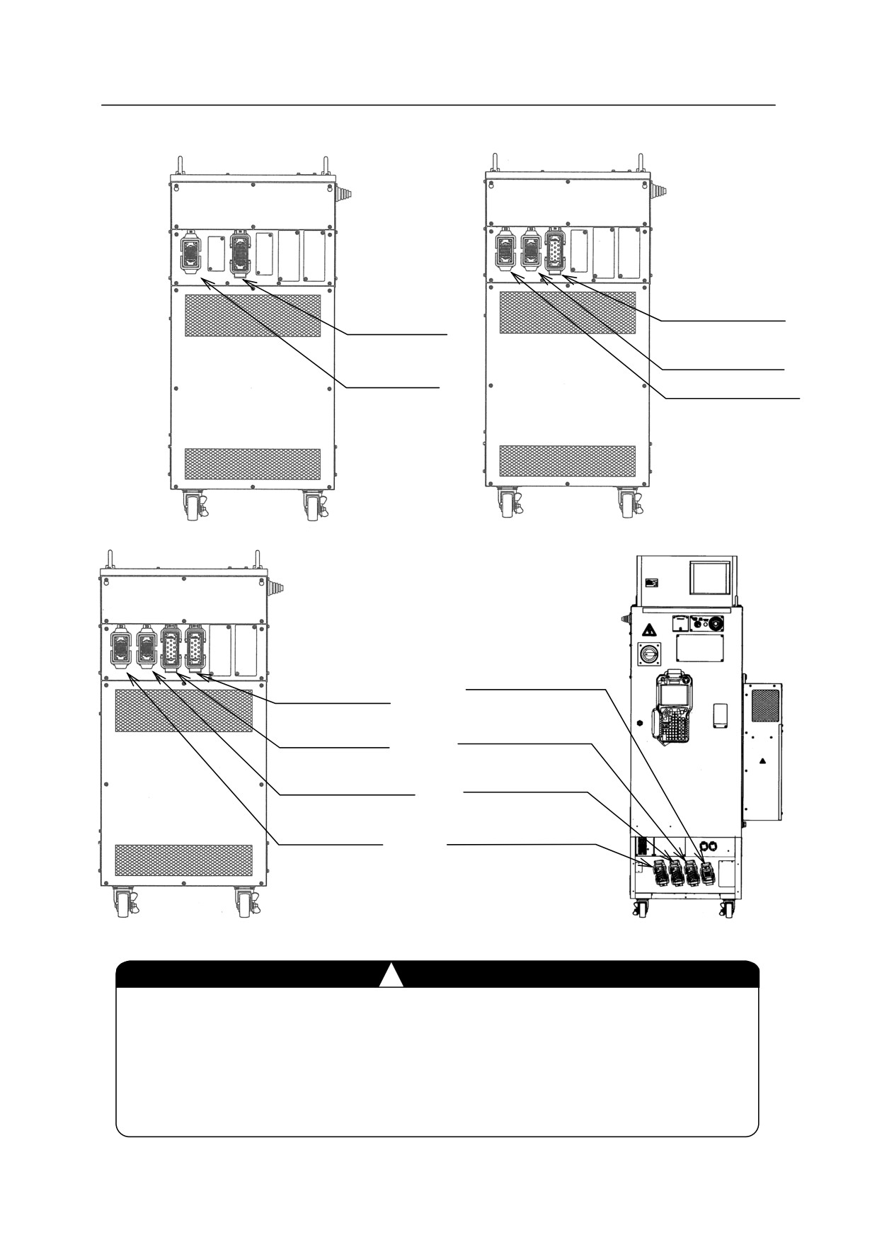
6. Connection Instructions
Major axis motor
Motor harness
harness (X4)
(X4)
Wrist axis motor
Signal harness
harness (X5)
(X3)
Signal harness (X3)
E20 controller
E22/E23 controllers
Signal harness
Wrist axis motor
(X3B)
harness (X4-2)
Major axis motor
Major axis motor
harness (X4B-2)
harness (X4-1)
Major axis motor
Brake and JT7
motor harness (X5)
harness (X4B-1)
Signal
Wrist axis motor+
harness (X3)
brake harness (X5B)
E24 controller
E28 controller
!
CAUTION
1. Fix each connector securely. The robot may malfunction if connectors loosen or
detach.
2. The harness should drop straight down from the connector. Because connectors
are located at the upper part of controller, the controller might topple over if the
connected harnesses are pulled to the controller side or to the rear direction.
81

6. Connection Instructions
Major axis
motor harness
Motor harness
(X4)
(X4)
Wrist axis
motor harness
Signal harness
(X5)
(X3)
Signal
harness (X3)
E30 controller
E32/E33 controllers
Wrist axis motor
harness (X4-2)
Major axis motor
harness (X4-1)
Brake and JT7
motor harness
(X5)
Signal
harness (X3)
E34 controller
!
CAUTION
1. Fix each connector securely. The robot may malfunction if connectors loosen or
detach.
2. The harness should drop straight down from the connector. Because connectors
are located at the upper part of controller, the controller might topple over if the
connected harnesses are pulled to the controller side or to the rear direction.
82
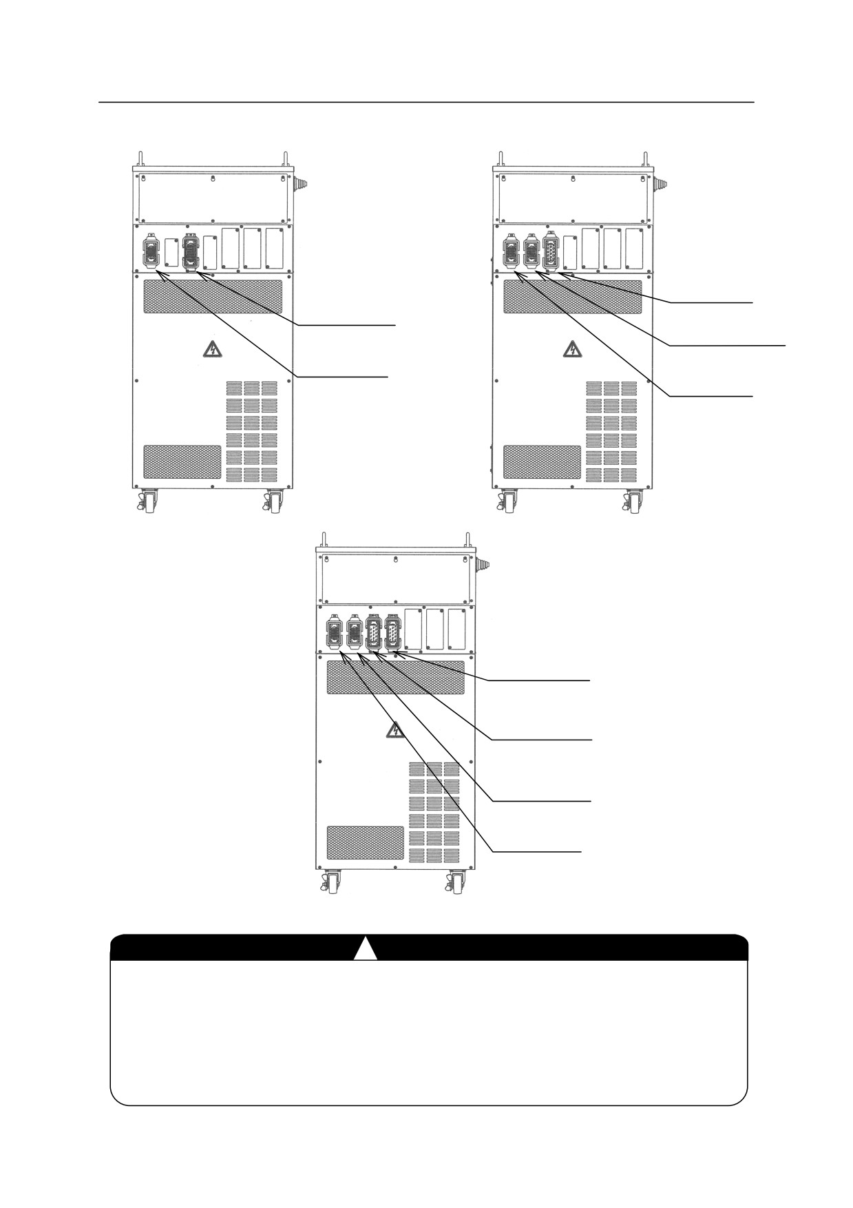
6. Connection Instructions
Major axis
motor harness
(X4)
Motor harness
(X4)
Wrist axis motor
harness (X5)
Signal harness
(X3)
Signal
harness (X3)
E40 controller
E42/E43 controllers
Wrist axis
motor harness
(X4-2)
Major axis
motor harness
(X4-1)
Brake and JT7
motor harness
(X5)
Signal
harness (X3)
E44 controller
!
CAUTION
1. Fix each connector securely. The robot may malfunction if connectors loosen or
detach.
2. The harness should drop straight down from the connector. Because connectors
are located at the upper part of controller, the controller might topple over if the
connected harnesses are pulled to the controller side or to the rear direction.
83
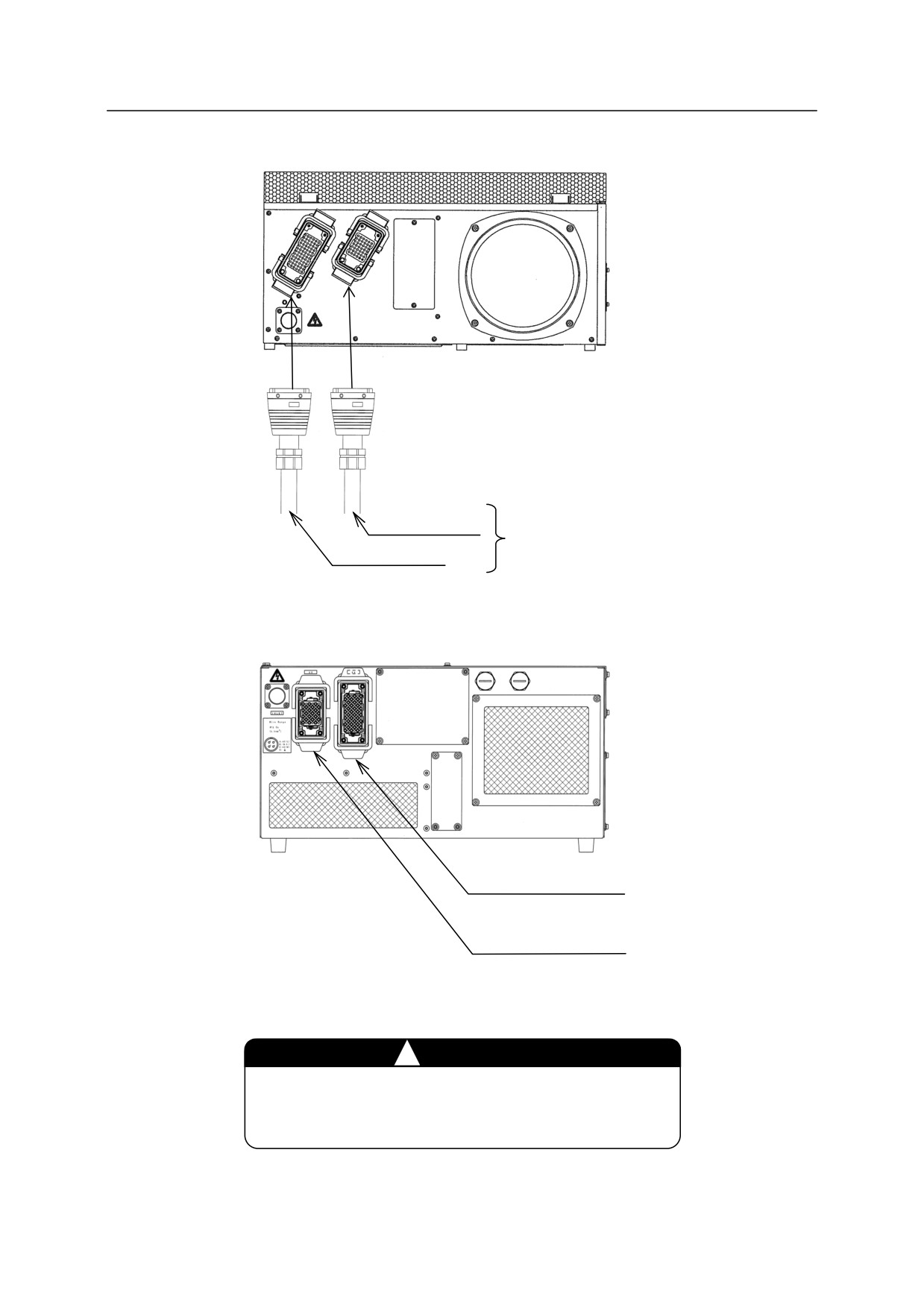
6. Connection Instructions
X4
X3
Signal harness
Keep space for reasonable treatment
Motor harness
of harnesses with straight connectors.
E7x controller
Motor harness (X4)
Signal harness (X3)
E9x controller
!
CAUTION
Fix each connector securely. The robot may
malfunction if connectors loosen or detach.
84
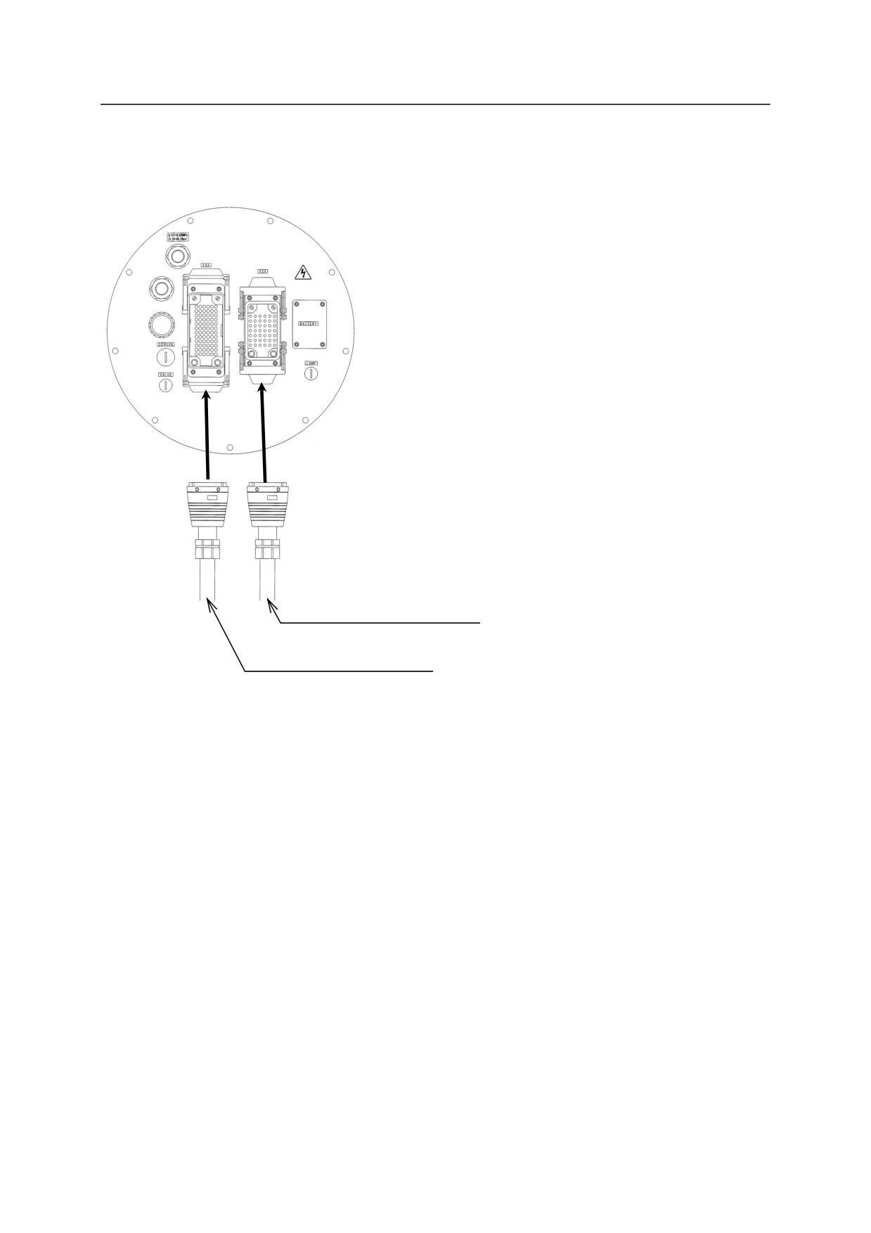
6. Connection Instructions
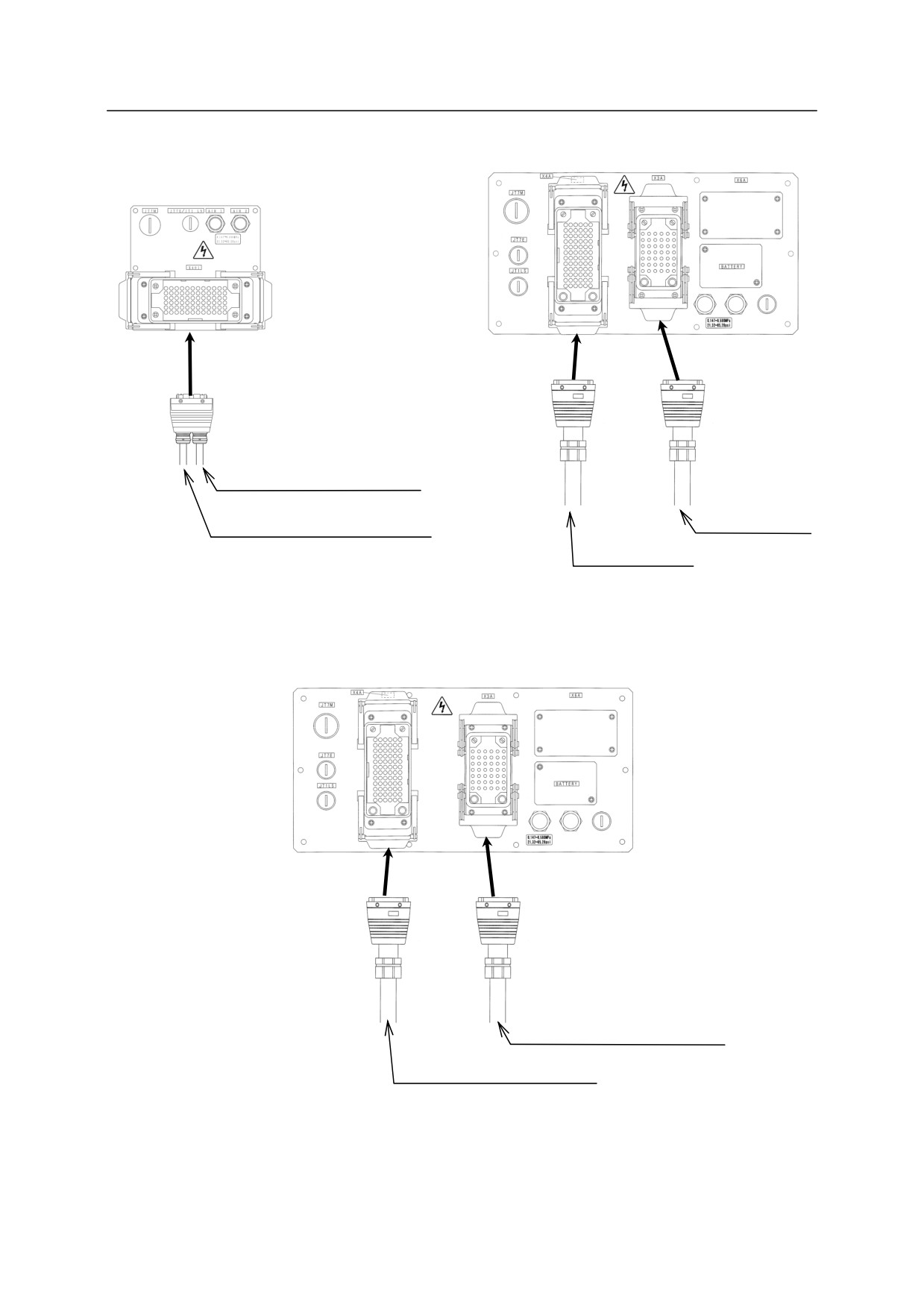
2. Arm side
YF003N
X4A
X3A
Signal harness
(Cable radius: 15.5-17.6 mm)
Motor harness
(Cable radius: 20.2-22 mm)
85
6. Connection Instructions
R series 03N/05N/05L
R series 10N/06L
X401
X4A
X3A
Motor harness
(Cable radius: 20.2-22 mm)
Signal harness
Signal harness
(Cable radius:
(Cable radius: 15.5-17.6 mm)
Motor harness
15.5-17.6 mm)
(Cable radius:
20.2-22 mm)
R series 20N/10L
㻌
X4A
X3A
Signal harness
(Cable radius: 15.5-17.6 mm)
Motor harness
(Cable radius: 20.2-22 mm)
86
6. Connection Instructions
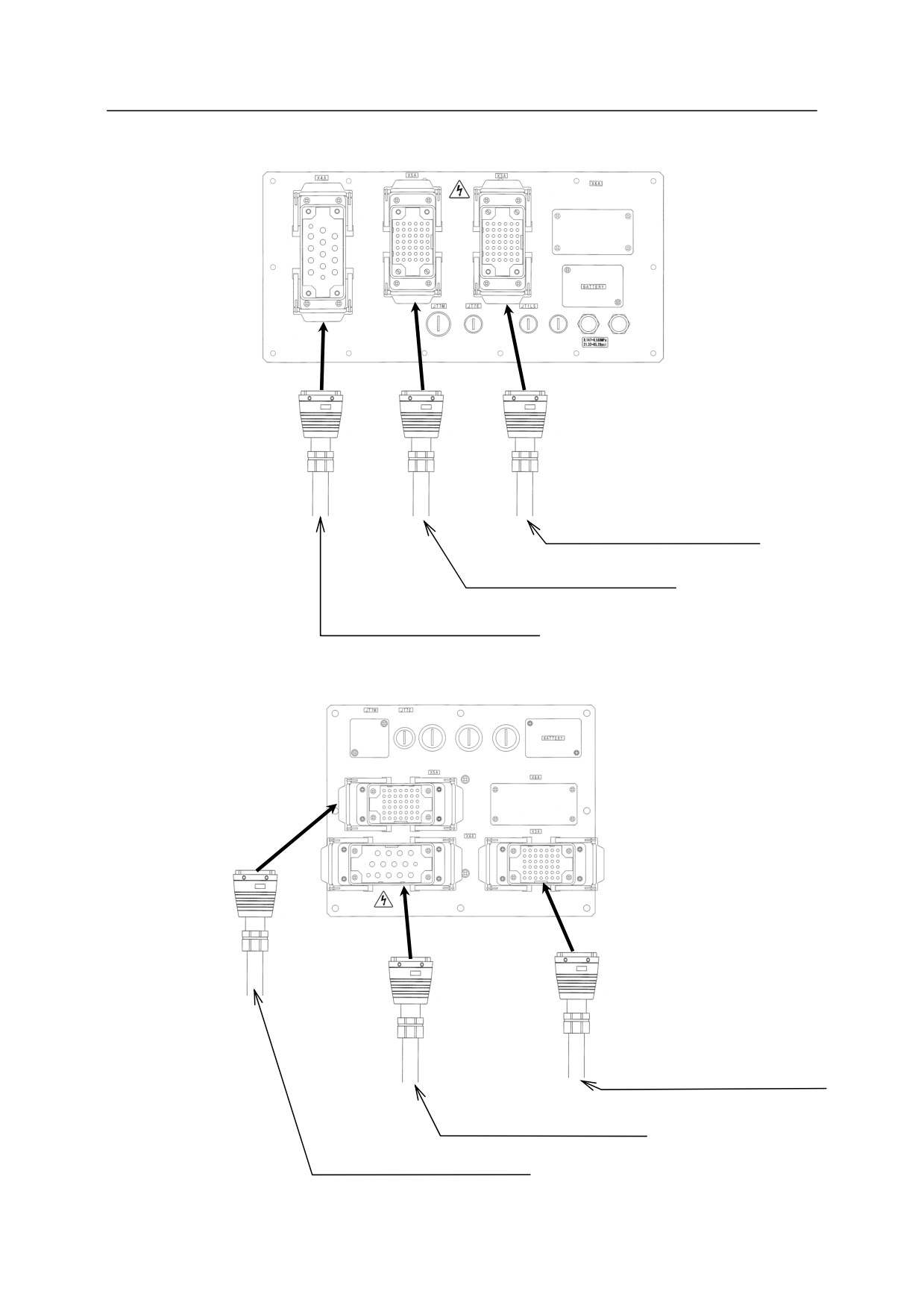
R series 30N/50N/80N/15X
X4A
X5A
X3A
Signal harness