OMRON NB-Designer OPERATION MANUAL (NB-series, 2020) - page 11
3 Functions of NB-Designer
9
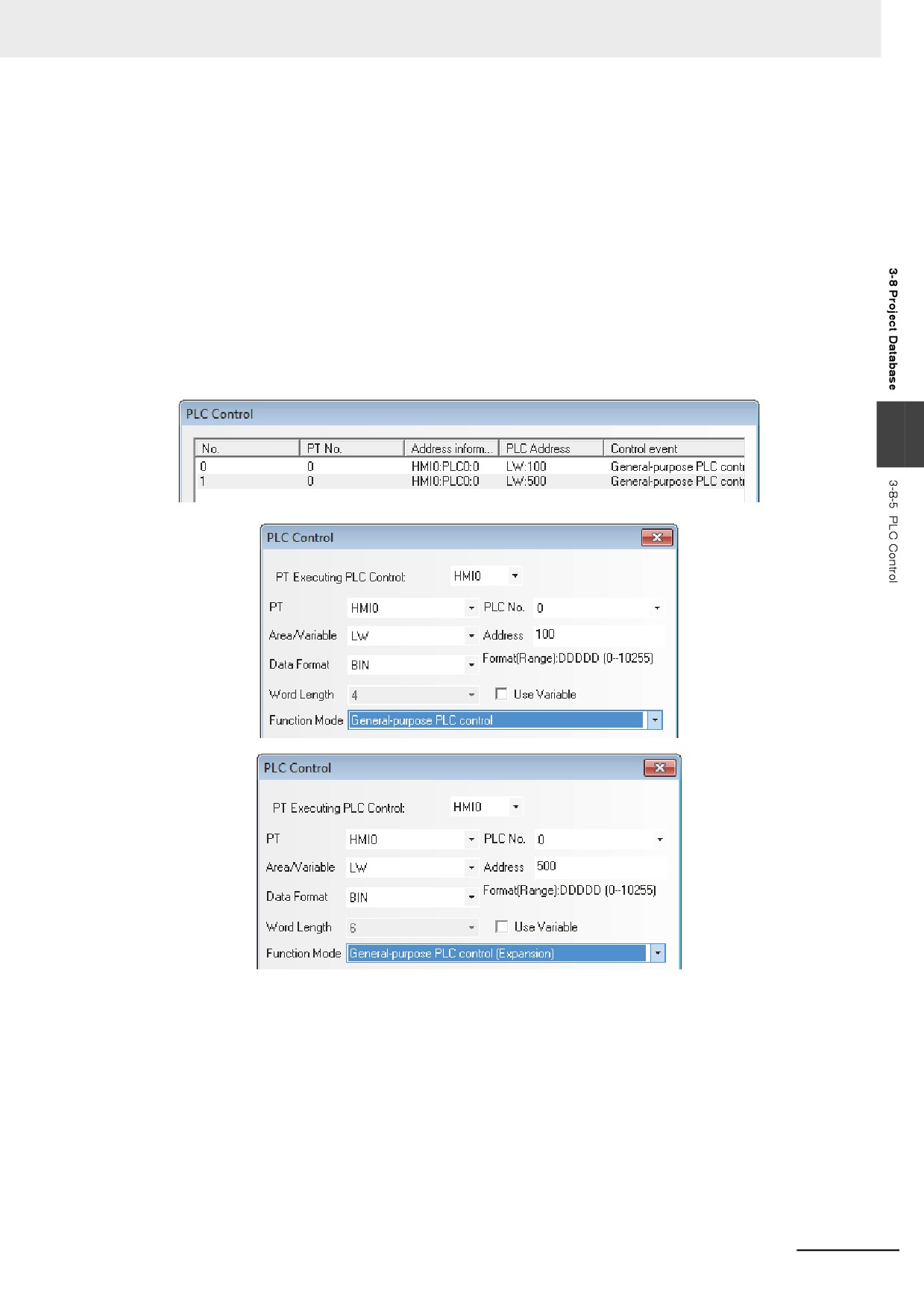
General-purpose PLC Control (Expansion)
General PLC Control (Extend) is similar to General PLC Control, but the occupied address is
different, i.e. General PLC Control occupies 4 words while General PLC Control (Extend)
occupies 6 words (extending “word” to “double-word”). Refer to the section of General-purpose
PLC Control for the details.
The method is as follows:
(1) Read Address: Similar to General-purpose PLC Control.
(2) Read Address + 1: Similar to General-purpose PLC Control.
(3) Read Address + 2: Refers to the address offset of the data memory of PLC during the
transmission and it occupies 2 words. Please note that this offset is specified from the
address memory with “Read Address + 6”.
(4) Read Address + 4: Refers to 2 words occupation.
3
3-263
3 Functions of NB-Designer
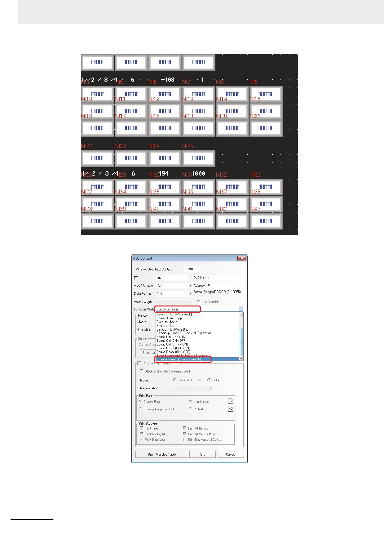
10 Change Screen (Ignore screen 0)
The difference between Switch Screens and Change Screen (Ignore screen 0) is as follows:
Switch Screens: When the value of specified address is 0, it will be switched to Screen 0.
Change Screen (Ignore screen 0): When the value of specified address is 0, screen
switching is not made.
3-264
3 Functions of NB-Designer
3-9
Macro Function
Macro is the function allows the user to create and execute the simple and original programs.
The user can add the functions such a arithmetical operations or discriminant of the conditions which
are not be supported by the basic functions of the NB-Designer. Using the Macro function, the user also
convert the display processing in the screen or the data processing used to be performed in the PLC.
This function allows the PC loading reduced. The Macro of the NB-Designer conforms to C Language
(ANSI C89).
3-9-1
Create a Simple Macro Program
This section provides a brief of the Macro variables.
The Macro variables are classified into two types such as internal variables and external variables.
• Internal variables: The variables are available only within the Macro Program. The internal variables
3
can be defined in the [Macro Variable Table] or the [Macro Editing Window].
• External variables: The variables are to read and write the values with the external controllers. The
external variables are necessary to be defined in the [Macro Variable Table] in
advance. The defined external variables can be used in the [Macro Editing Win-
dow].
Storage Format of the variables used in the [Macro Variables Table]
Storage Format
Data length
Descriptions
Bit
1bit
Bit variable with 2 statuses of 0 and 1.
Signed short
1 word (16 bits)
Signed short-integer variable with a range of -32768 to 32767.
Unsigned short
1 word (16 bits)
Unsigned short-integer variable with a range of 0 to 65535.
Signed int
2 word (32 bits)
Signed-integer variable with a range of -2147483648 to
2147483647.
Unsigned int
2 word (32 bits)
Unsigned-integer variable with a range of 0 to 4294967295.
Float
2 word (32 bits)
Single-precision floating-point variable with a range of
-3.4E+38 to +3.4E38
Double
4 word (64 bits)
Double-precision floating-point variable with a range of
-1.79E+308 to +1.79E+308
Read/Write type of Macrocode Variable
Read/Write Type
Descriptions
Read
The values of Macro are read before being executed, and reading operation is not
performed during Macrocode execution.
Write
The values of Macro are written to the specified variable at one time after being
executed, and writing operation is not performed during Macrocode execution.
Read/Write
The values of Macro are read before being executed, and written after being executed.
3-265
3 Functions of NB-Designer
Storage Format used in Macro Variable
Data Type
Data length
Descriptions
Bool
1bit
Bit variable with 2 statuses of 0 and 1.
(Signed) char
1byte(8bit)
Signed short-integer variable with a range of -128 to 127.
Unsigned char
1byte(8bit)
Unsigned short-integer variable with a range of 0 to 255.
(Signed) short
1word (16bits)
Signed short-integer variable with a range of -32768 to 32767.
Unsigned short
1word (16bits)
Unsigned short-integer variable with a range of 0 to 65535.
(Signed) int
2word (32bits)
Signed-integer variable with a range of -2147483648 to
2147483647.
Unsigned int
2word (32bits)
Unsigned-integer variable with a range of 0 to 4294967295.
Float
2word (32bits)
Single-precision floating-point variable with a range of
-3.4E+38 to +3.4E38
Double
4word (64bits)
Double-precision floating-point variable with a range of
-1.79E+308 to +1.79E+308
Create a Macro program with basic arithmetical function in the following figure.
Read 2 signed data from LW0 and LW1, make LW0 divided by LW1, then place the result of the
division in the 4 words from LW2 to LW5.
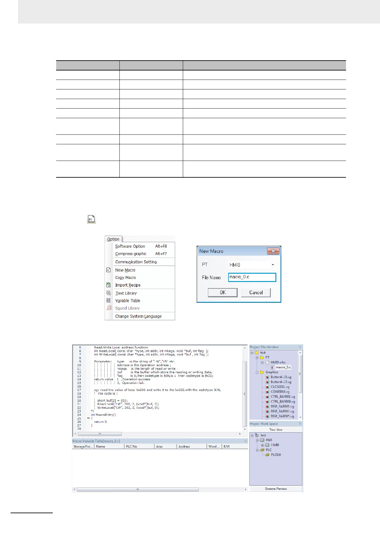
Press the
(Add Macro) icon in the database toolbar, or click [Macro] in the [Option] menu, then the
following dialog box will pop up.
Select the PT No. and input the file name, then click “OK” to enter the Macro Editing Window (i.e.
[macro_0.c]), as shown below.
3-266
3 Functions of NB-Designer
Before writing the Macro, please predefine the I/O variables.
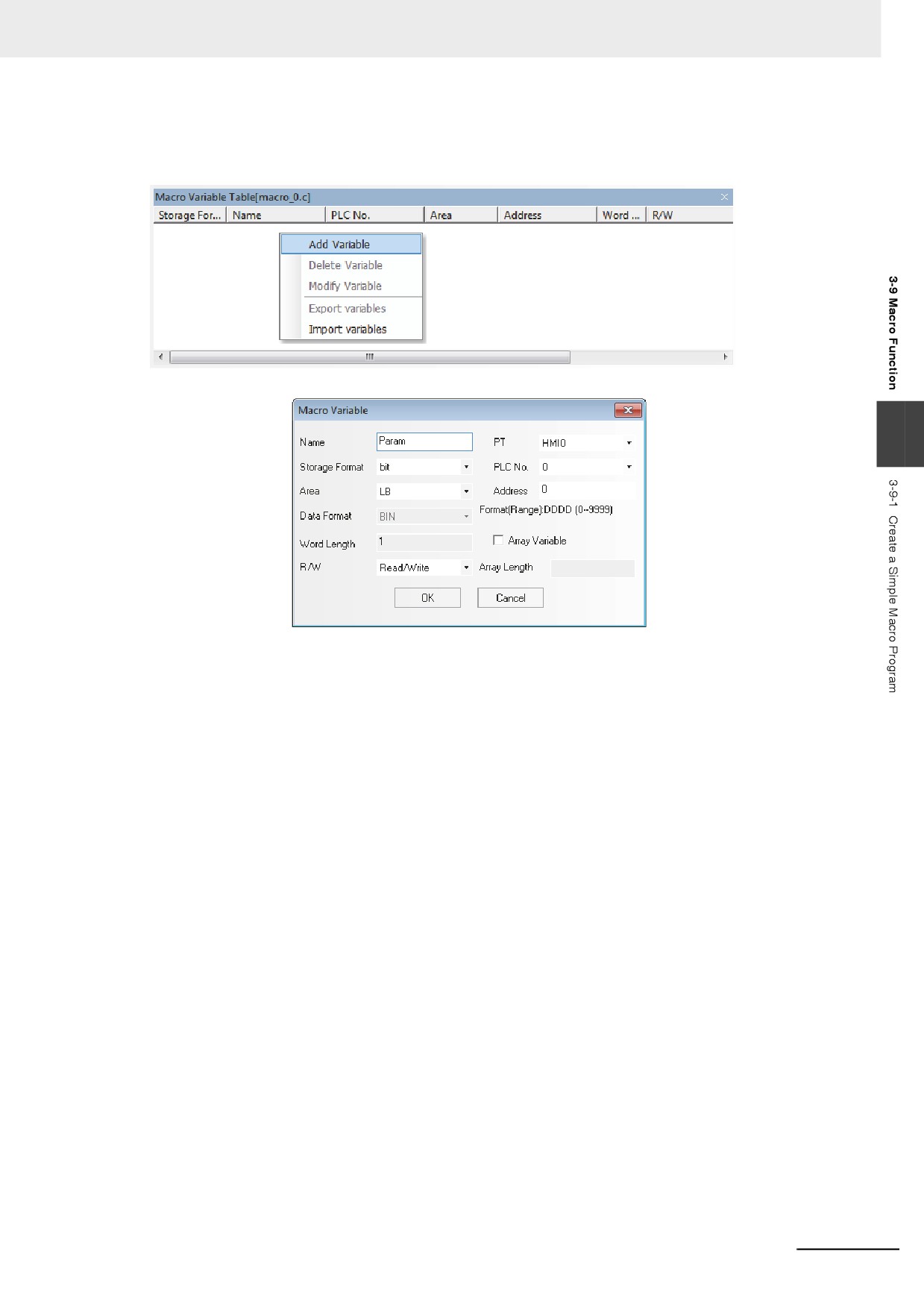
Right-click the mouse in the “Macro Variable Table [macro_0.c]” window to make the following menu
pop up.
Select “Add Variable” to make the following dialog box pop up.
3
Firstly specify the variable name.
There are 3 kinds of variables - Read variable, Write variable and Read/Write variable. Read variable
means Macro will obtain the value of the variable from the specified address; Write variable means the
result after the Macro executed will be written into the specified address and Read/Write variable
incorporates the features of the Read variable and the Write variable. Therefore, Read, Write and
Read/Write are the 3 different variables for the same address. It is recommended to use _R, _W and
_RW to differentiate the variables when you specify their names.
In the following example, LW0 and LW1 are Read variables and LW2 is Write variable, so we name
them as follows:
LW0_R, LW1_R, and LW2_W. Please note that the regulations for the variable names are consistent
with that for C language, and the special attention must be paid to the following points:
(1) The variable name is case-sensitive;
(2) The variable name can’t be the number or begin with the number or include some special
characters such as space, slashes etc.
(3) The variable name can’t be any reserved words of C language.
(4) Specify the array length in the range from 2 to 1024. The array length of the value in unsigned
short type cannot be specified to 4. The array length of the value in int type or float type cannot be
specified to 2. (The specification of the function is different from the one of the standard C
language)
3-267
3 Functions of NB-Designer
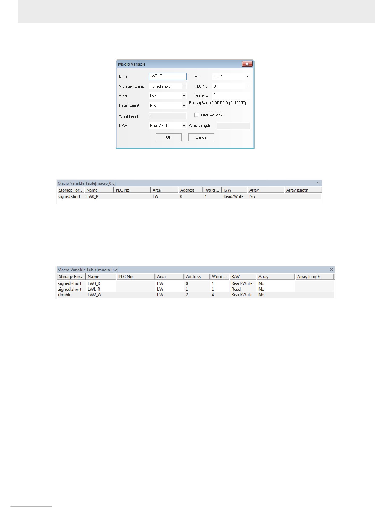
In the example below, the Properties of LW0_R are set as follows:
Here, specify “signed int.” from “Storage Format”, “Read” from “R/W”, “LW” from “Area” and “0” from
“Address” respectively. After the specification, click the “OK” button, then this variable will be seen in
“Macro Variable Table [macro_0.c]” window.
Note The variables used in the Macro are necessary to be registered to the [Macro Variables Table] in advance.
Specify LW1_R and make its address to LW1, then set the address of LW2_W to LW2 by the same
method.
Note When the Storage Format is set to “double”, the Word Length will automatically become 4, i.e. this variable
will occupy LW2 to LW5.
After the completion of setup, the “Macro Variable Table [macro_0.c]” window is shown as below:
After defining the variables, we should write the following Macro:
int MacroEntry()
{
//LW0 is divided by LW1and LW2 is obtained
LW2_W=LW0_R/LW1_R;
return 0;
}
Once it is saved, the simple Macro is completed. At this time, go to the Edit Window to make the
editions as shown below:
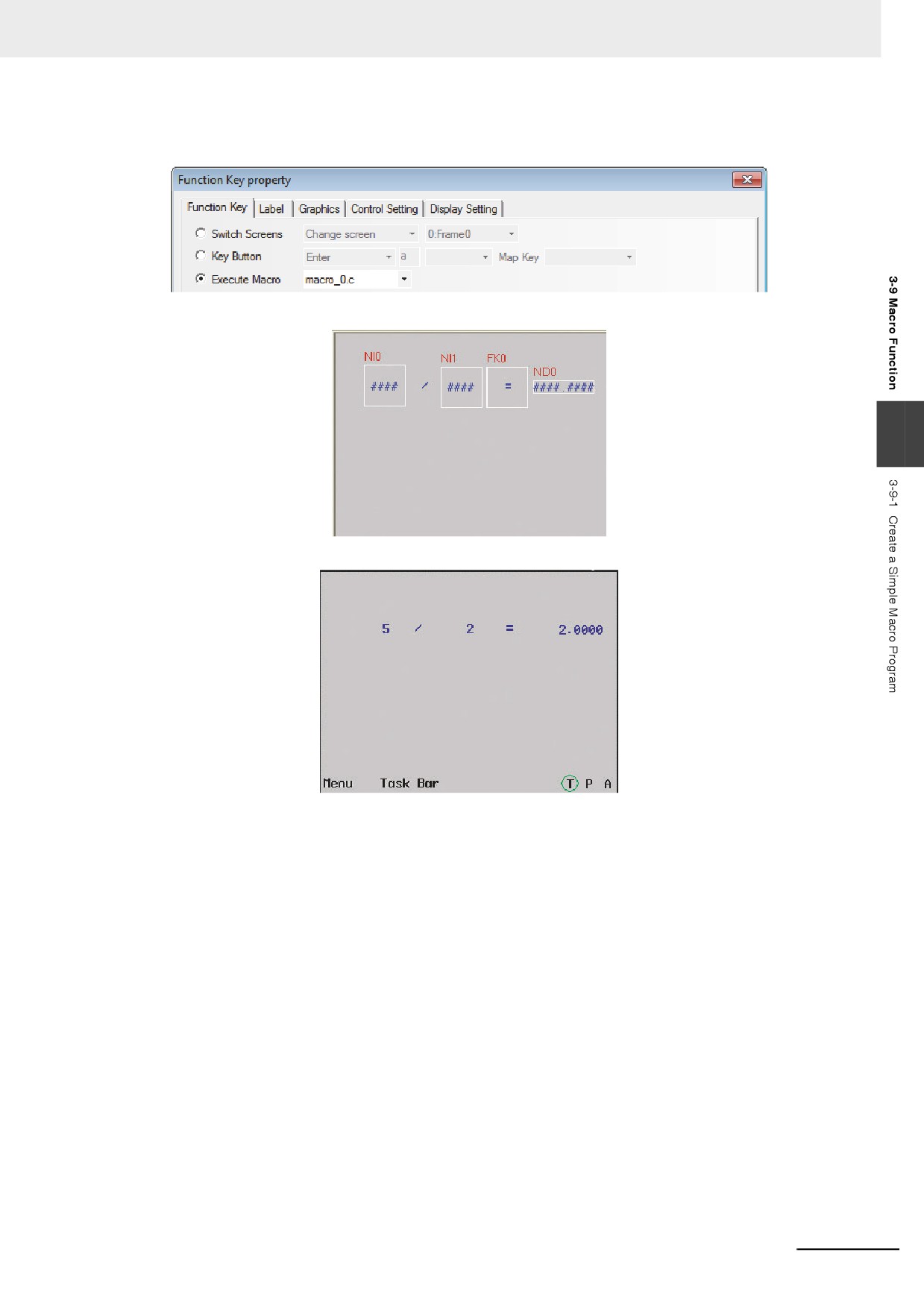
Place 2 Number Input components corresponding to LW0 and LW1 respectively;
Place 1 text component and enter “/” to represent division.
Place 1 Number Display component corresponding to LW2, and set the Storage Format to “double” (i.e.
double-precision floating-point) and both the Integer and Decimal to “4”;
3-268
3 Functions of NB-Designer
Place 1 Function Key to execute Macro, and select “macro_0.c” in the drop-down menu as below and
input “=” in the label:
The Edit Window is displayed as follows.
3
Perform the offline test, input 5 into LW0 and 2 into LW1, and you will see the result as shown below:
The result should be 2.5000 instead of 2.0000.
LW0_R and LW1_R are [signed short] so that the division of one variable by another variable both in
integer type results in the variable also in integer type. In order to resolve this problem, the variable to
perform the division is necessary to be casted in [double] as follows.
LW2_W = (double)(LW0_R)/LW1_R;
3-269
3 Functions of NB-Designer
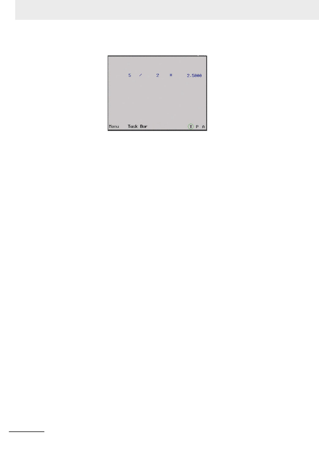
After editing the Macro in the procedure as the above, perform the test again. Then the result as follows
should be out.
Now the basic specification is completed. However, the Macro still have a problem. When entering “0”
into LW1 and executing the Macro, an error occurs and the error can affect the normal operation of the
system. In this case, a check should be entered into the operand.
Change the codes shown as below.
int MacroEntry()
{
//Judge whether LW1 is 0 or not in order to prevent “Divide-by-zero overflow” ;
if (LW1_R!=0)
//LW0 divides LW1and LW2 is obtained
LW2_W = (double)(LW0_R)/LW1_R;
return 0;
}
Execute it again. If the divisor is 0, the Macro will not execute division. Therefore, the program safety
will be improved.
3-270
3 Functions of NB-Designer
z Macro Optimization
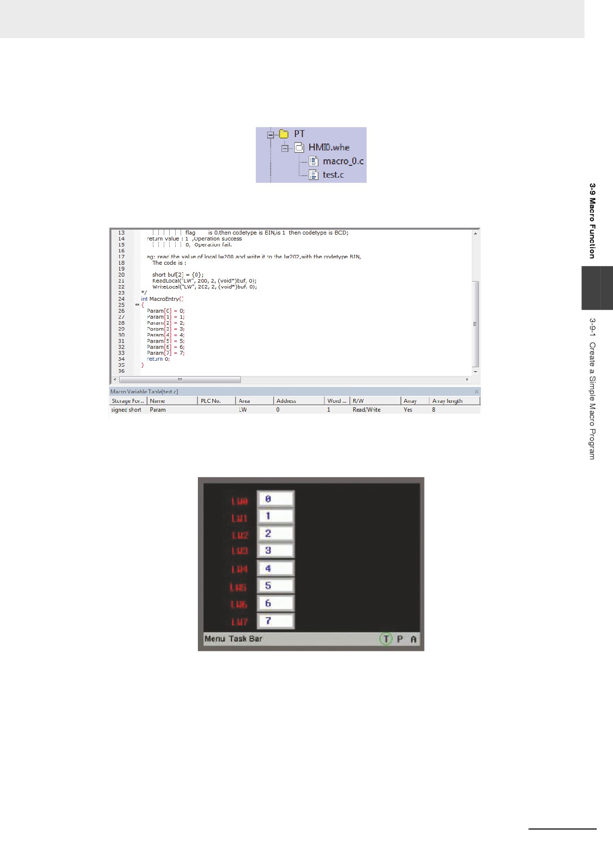
Create the new Macro with the optional name (test.c). A brief provides of the Macro using the array
variables. The array variables can be defined only for the one-dimensional array.
For example:
Create one array variable with the length of 8. The definition of variable is shown as below.
3
(1) Place 8 Number Display components LW0 to LW7 with the consecutive addresses in Frame 0, and
make the timer to execute “test.c”.
(2) Perform the test, and the values displayed in Number Display components are same as the values
assigned in the Macro.
3-271
3 Functions of NB-Designer
3-9-2
Macro and Specification of Operation with Read/Write Variables
In this part, we will provide the description about specification of the operating Macro, and we will also
provide the description that should be noted when you use Macro.
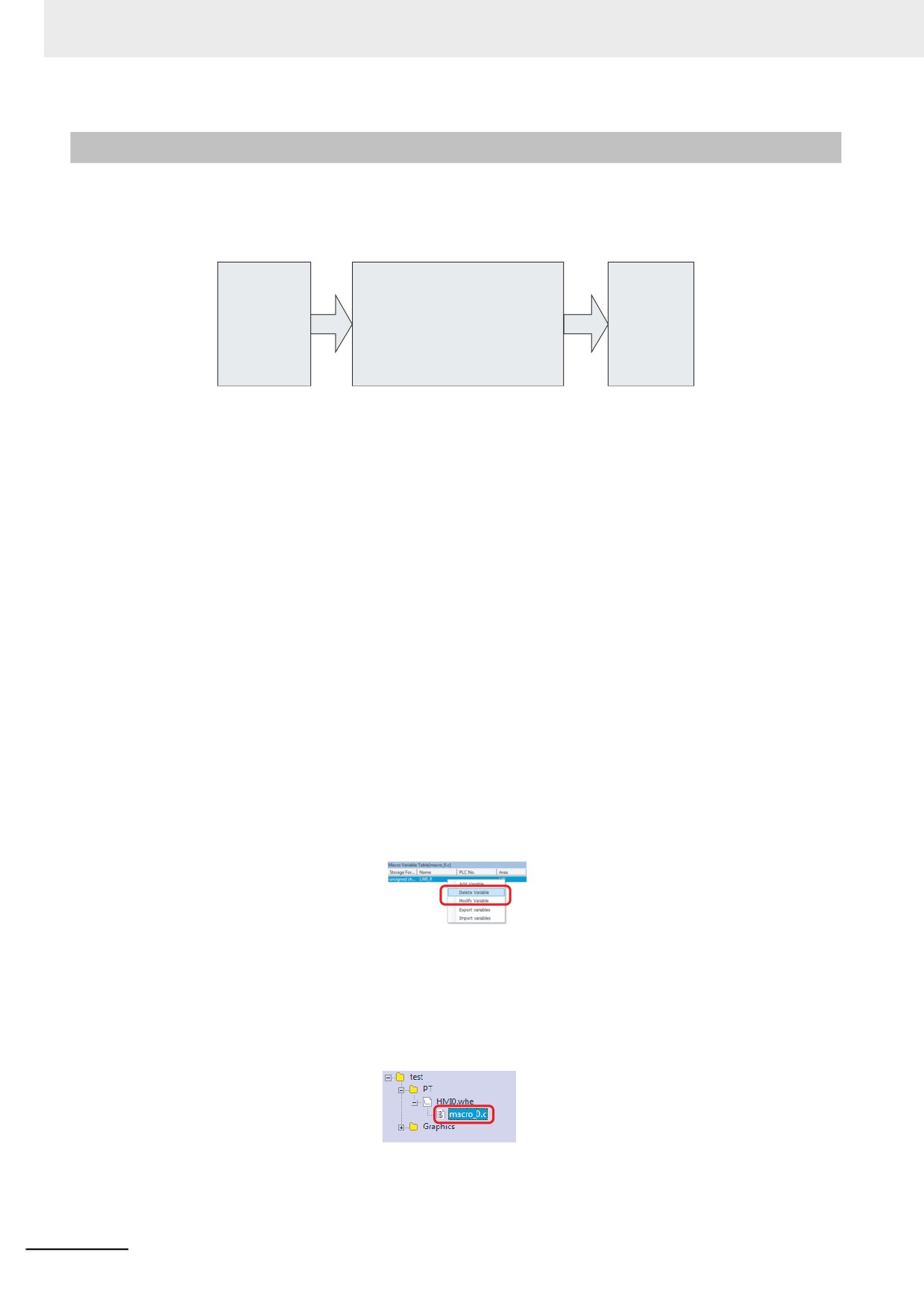
The Macro can be regarded as a black box for input and output. Taking the example of the division
program which was mentioned in the first part of this section, the flow of the procession is as follows:
Macro
Read variable
int MacroEntry()
Write variable
(Read only)
{
(Write only)
LW0_R
If(LW1_R!=0)
LW2_W
LW1_R
LW2_W=(double)(LW0_R)/LW1_R,
Return 0;
}
The specification of the operation is as follows: Before the program is executed, the value from the
memory for LW0 and LW1 will be assigned to Read variables LW0_R and LW1_R, then Macro will be
executed. Later, after Macro function returns, the value of variable LW2_W will be written into LW2.
Therefore, the variables of the Macro performs like the copy of the memory and even if the variables
are modified, the value of the memory is not be changed.
Note 1
Since the read variables do not read the memory value during executing the Macro, the read value remain
the same as the one when the Macro read during operating. Even if the memory value is modified from the
external device during the Macro executing, result of the operation is not be affected.
2
Even if the memory value is written with a value from the external device during the Macro executing, the
memory value will be updated to the result of the execution of the Macro after the Macro completed.
3
The read variable is read only and the write value is write only. Therefore, writing the value to the read
variable or reading the writing variable by using the Macro are not impossible. Similarly, when one address
is used for reading and writing at the same time, use two different names by contrast for the variables such
as LW0_R and LW0_W for LW0.
4
The global variables or the static variables are not available in the Macro. If the data should be retained
using the global variables, use the PT internal memories such as LW or LB.
5
The values which output the result of the Macro should be prepared.
The description of the other functions are provided as follows.
(a) Modify or delete the variable in Macro.
Open the [Project File Window] and double-click the Macro file corresponded to open the [Macro
Variables Table] dialog box. Right-click the variable to select [Delete variable] or [Modify Variable].
Right-click the variable
to select [Delete variable]
or [Modify Variable]
Please be careful because the deleted variables can’t be restored.
(b) Delete the whole Macro file.
Open the Project File Window, press “Delete” key after selecting the corresponding Macro file.
Select and press
“Delete” key.
Please be careful because the deleted Macro files can’t be restored.
3-272
3 Functions of NB-Designer
3-9-3
Macro Triggering
There are many flexible methods for triggering Macro. Using the triggering methods for Macro flexibly
can realize more flexible and powerful functions conveniently.
NB-Designer currently supports the following methods for triggering Macro:
1
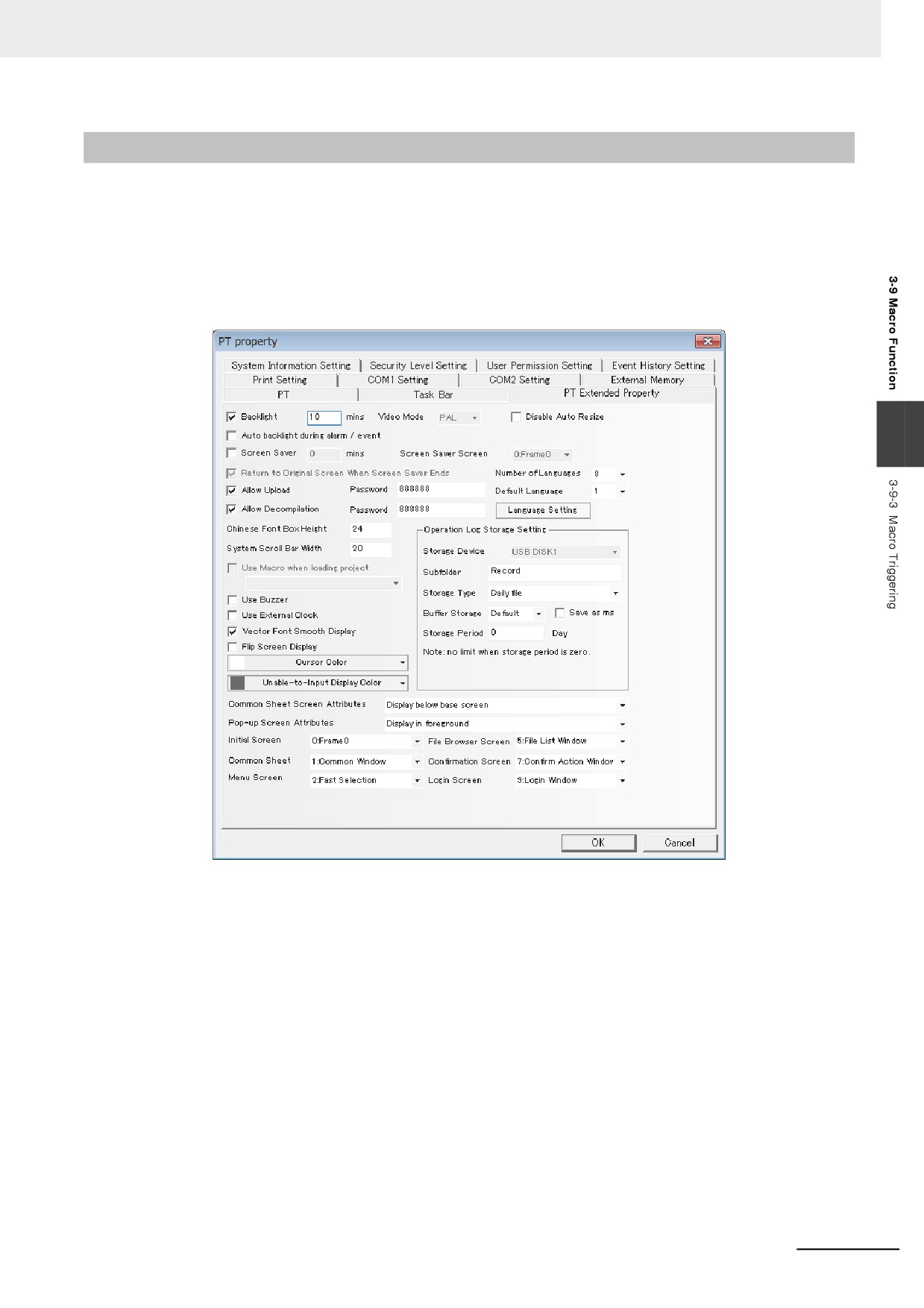
Macro when loading project
Check the “Use Macro when loading project” check box in the “PT Extended Properties” tab.
3
2
Function Key
Using “Execute Macro” function of Function Key to trigger the Macro is a kind of common
triggering method.
3
Timer
Executing the [Execute Macro] function by the Timer function allows the combination of the
Macro and the Timer function.
3-273
3 Functions of NB-Designer
4
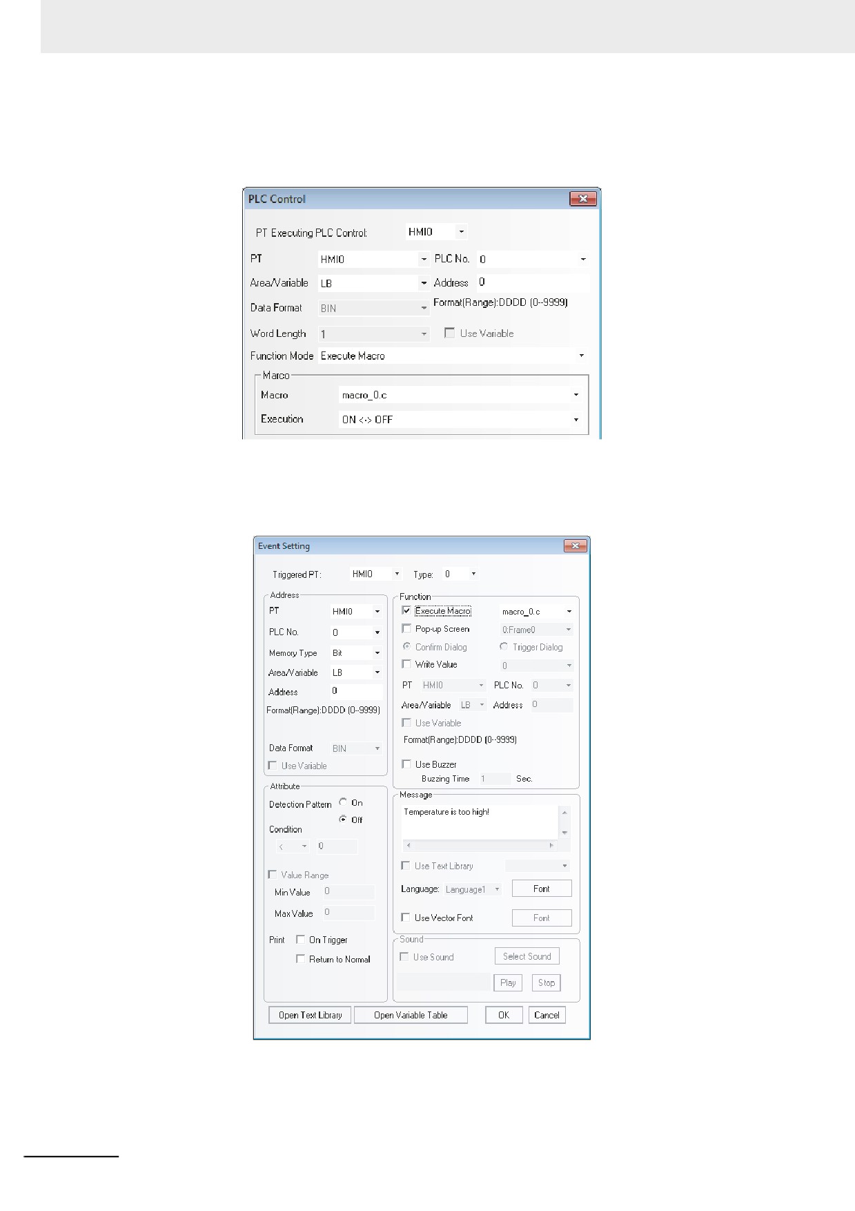
PLC Control
Specify the PLC Control as follows and select the [Execute Macro] and then the Macro will be
executed when the specific bits are matched to the condition previously specified.
5
Event
Setting the [Execute Macro] as below allows the Macro execution when a certain condition is
satisfied.
3-274
3 Functions of NB-Designer
6
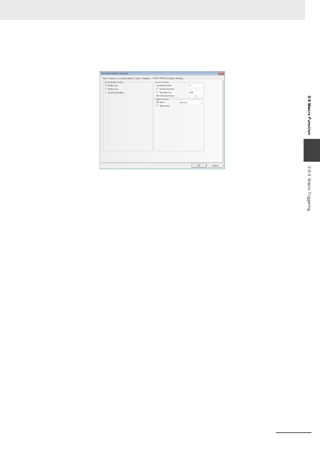
Control Setting of component
Checking [Macro] of Triggering action in the tab [Control Setting] as the lower figure shown
allows the Macro to be executed when the component is touched.
3
3-275
3 Functions of NB-Designer
3-9-4
Other Descriptions
1
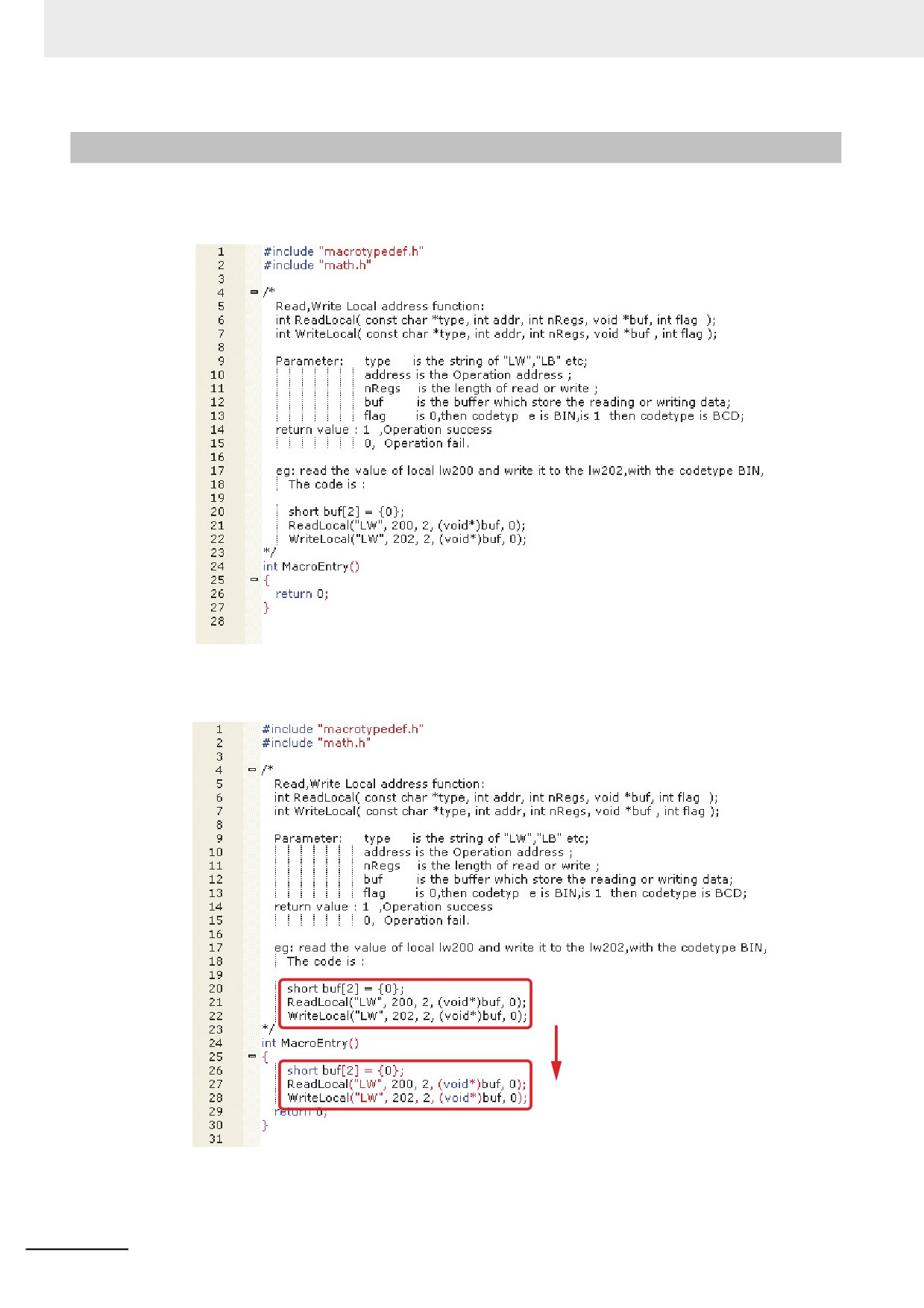
The Macro Editing Window can display the emphasis of the keywords.
In the top of the default Macro, a demo program is described for explanation.
If the entity part of the Macro program is copied and pasted in the following figure, you can see
that the color of the keywords is changed. The short/void are colored in blue and the LW is
colored in red. The part enclosed by “/*” and “*/” is the comment.
3-276
3 Functions of NB-Designer
2
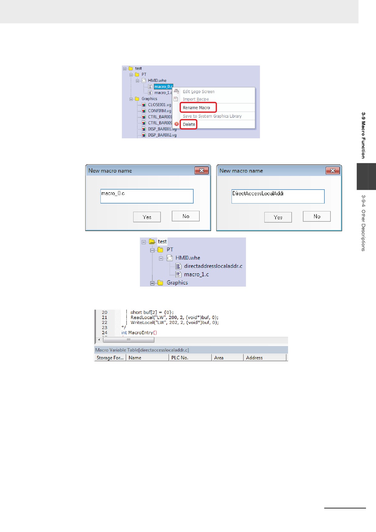
After the Macro creation, you can rename the Macro.
Right-click the Macro name, and you can see the options of [Rename Macro] and [Delete], and
input the new name after the dialog box pops up after clicking “Rename Macro”.
3
3
It supports the direct access to the local address of the PT without defining the variables.
As shown above, even if no variables are defined in the Macro, the direct access to the local
address of the PT, i.e. reading or writing the local address.
int ReadLocal(const char *type, int addr, int nRegs, void *buf, int flag);
int WriteLocal(const char *type, int addr, int nRegs, void *buf, int flag);
3-277
3 Functions of NB-Designer
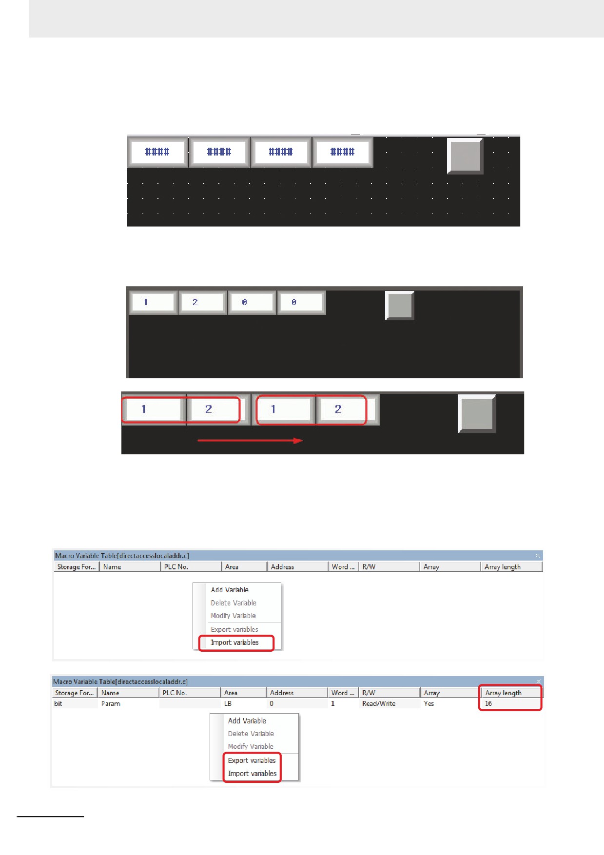
“nRegs” refers to number of words. That’s to say, the program will read 2-word data beginning
from LW200 and then write 2 words to LW202. In order to confirm this code segment will be
executed successfully, you should place 4 Number Input components and 1 Function Key to
execute the Macro in the Edit window, as shown below:
Macro
Perform the offline test:
Make LW200=1 and LW201=2, then click the [Macro] button, and you will find LW202=1 and
LW203=2. The Macro is executed normally.
Macro
Macro
4
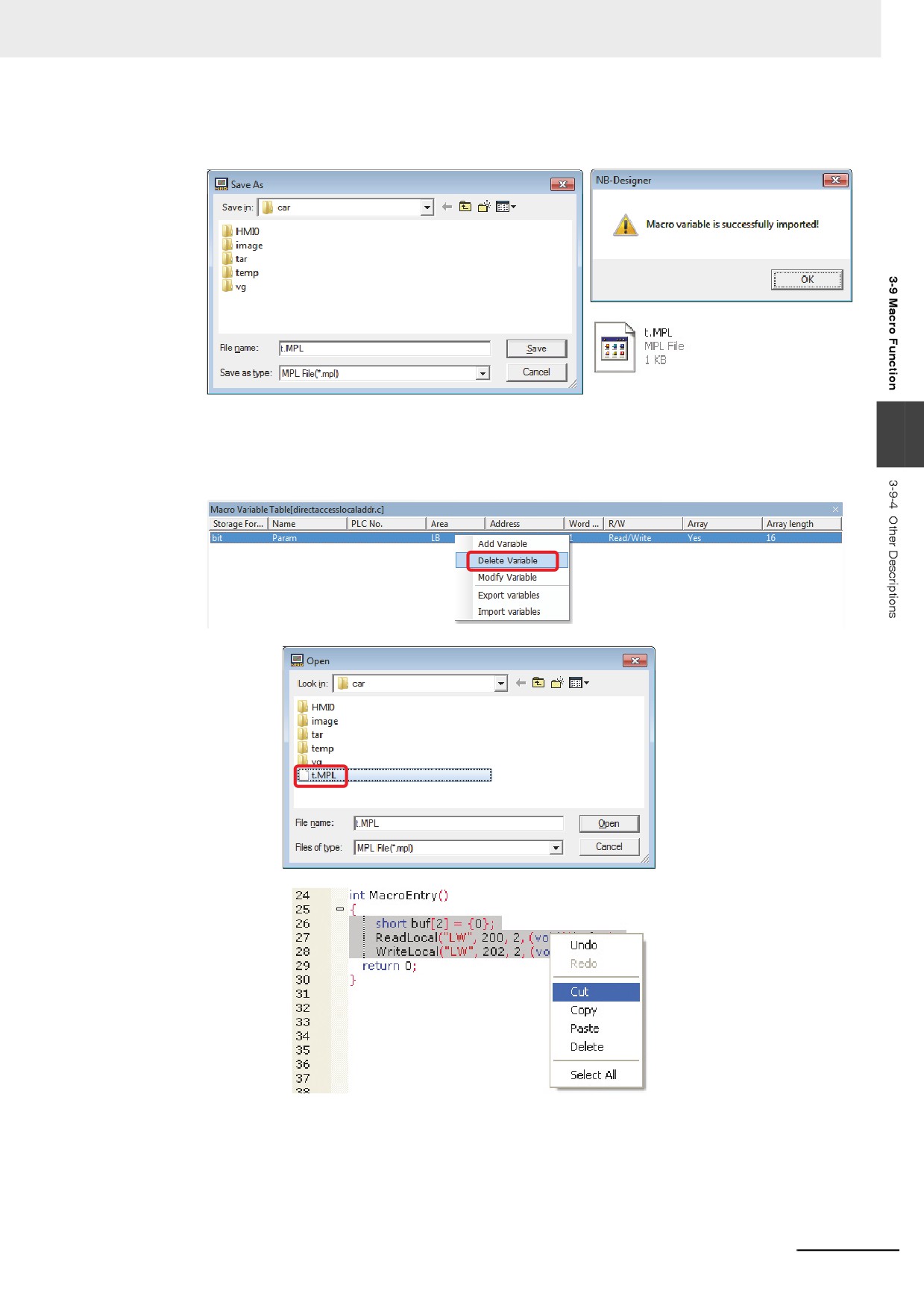
[Import variable/Export variable] functions are provided for user to copy Macro variables and
Macro.
Right-click “Macro Variable Table [directaccesslocaladdr.c]”, you will see the [Import variables]
option; and you will see the [Export variables] option is also valid after you have created a new
variable.
3-278
3 Functions of NB-Designer
First click the [Export variables] option to make “Save As” dialog box, and input the file name “t”
with the extension as “.MPL”, then save it into the optional folder.
Clicking the [Delete Variable] option and the [Import Variables] option allows the importing
3
variables. Such operation can be made among the different projects. Select the code which
should be copied if it is a program and right-click the [Copy] followed by pasting the code to the
intended location.
3-279
3 Functions of NB-Designer
5
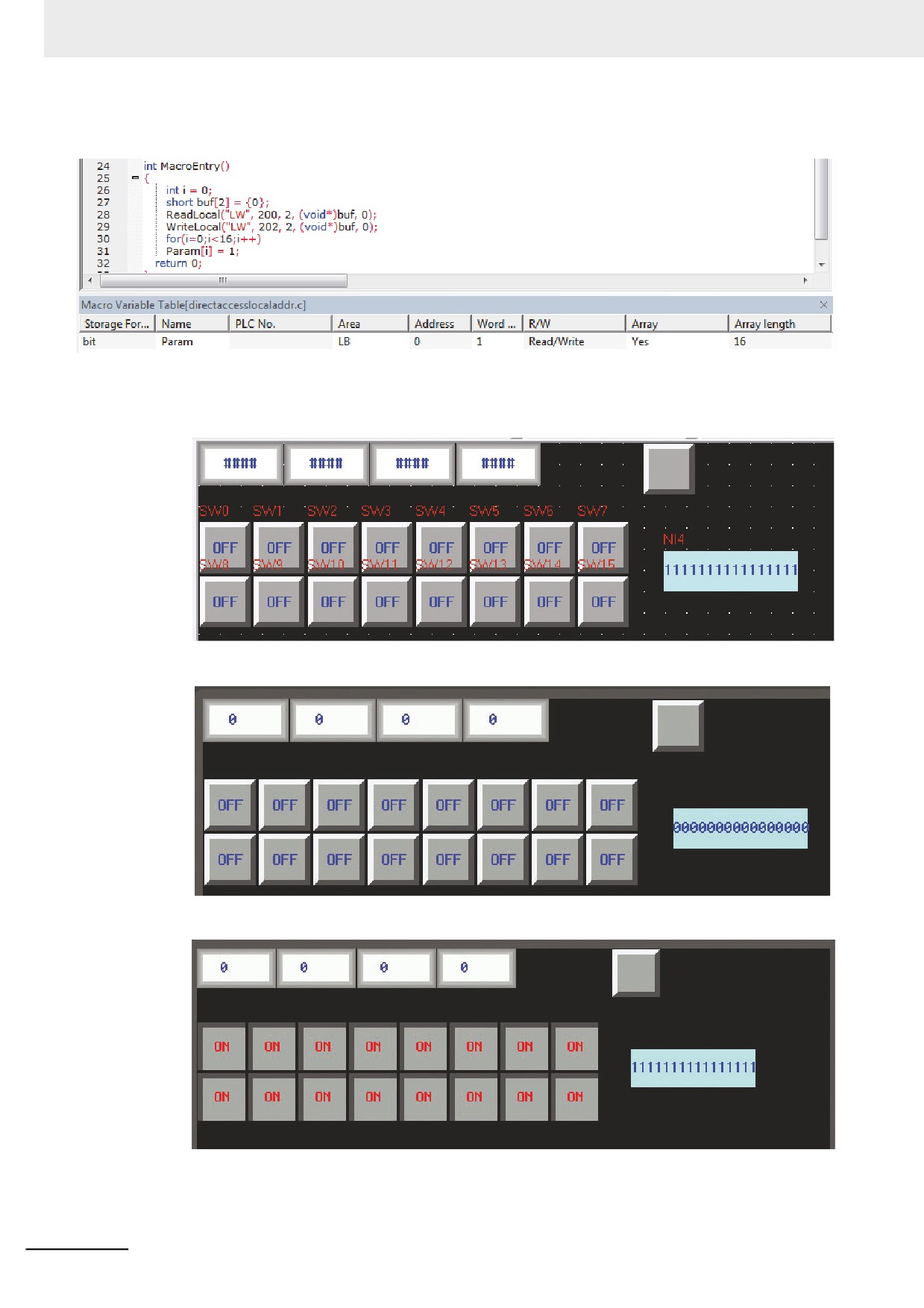
It supports the array variables in bit format.
Prepare array variables in bit format allocated L.W.B. 0.0 to 0.f and create a Macro which
writes “1” to all the elements in the array. Place 16 Bit Switches with the addresses of LW.B
0.0~0.f as well as 1 binary Number Input component with the address of LW0.
Macro
Perform the offline test:
Macro
After [Macro] is clicked, the display will be shown as below:
Macro
3-280
3 Functions of NB-Designer
6
Supports Direct Drawing in the Screen (Description of PT Drawing Function)
The Macro executing function allows the user to call drawing function.
Drawing functions adopt rectangular coordinate system of screen: point of origin locates in the
upper-left corner, and the X-axis extends rightward while the Y-axis extends downward.
(1) Definition of Struct
Add 3 structs: PenParam, BrushParam and Point.
(a) Pen structure “PenParam”
typedef struct penparam
{
short type;
short width;
int color;
3
}PenParam;
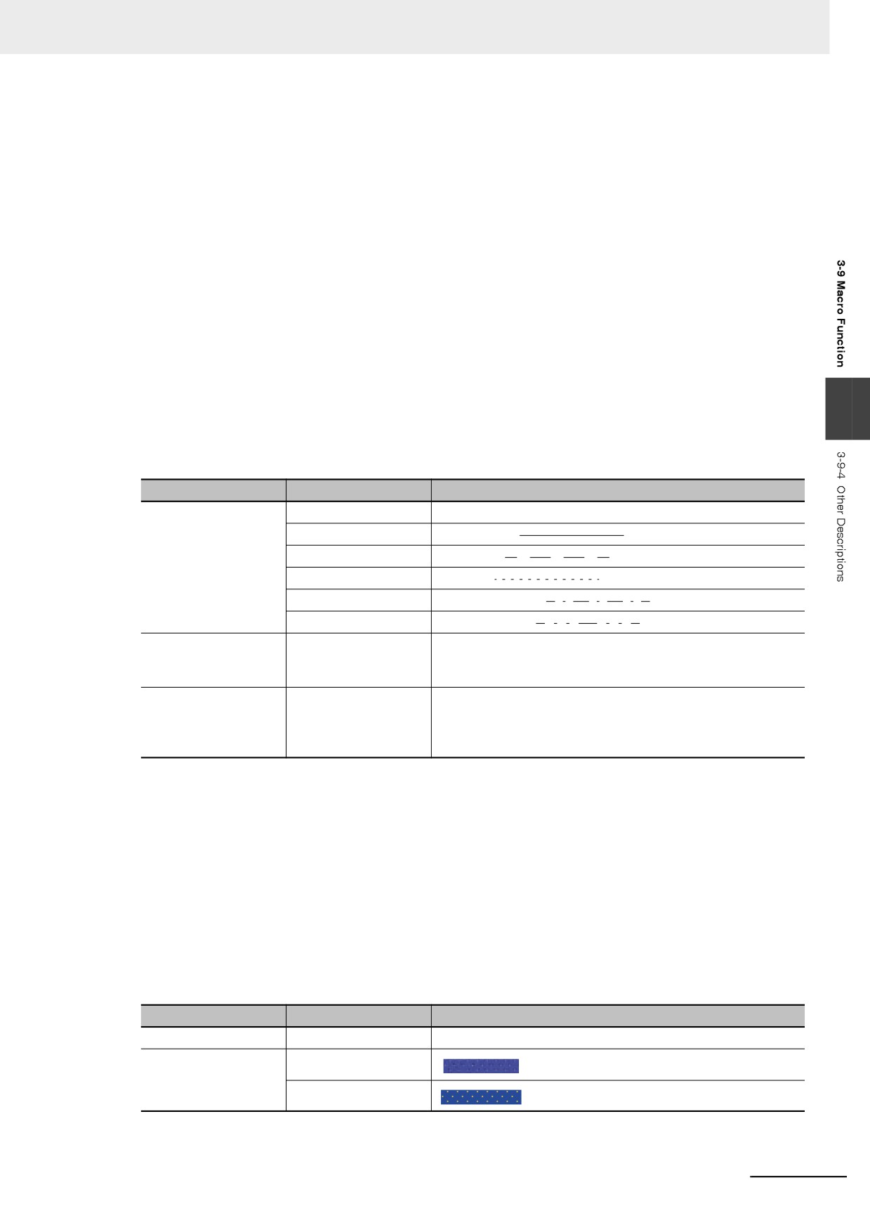
PenParam is mainly used to set the type, width and the color Properties of the pen.
And the value range is as follows.
Parameter Name
Value
Descriptions
Type (Pen type)
PS_NULL
No pen
PS_SOLID
Smooth line (
)
PS_DASH
Dash line (
)
PS_DOT
Dot line (
)
PS_DASHDOT
Dash-dotted line (
)
PS_DASHDOTDOT
Dot-dotted line (
)
Width (Pen Size)
1~8 (Unit: pixel)
If the input value is less than the minimum value 1 or greater
than the maximum value 8, the system will automatically set it
to the minimum value or the maximum value respectively.
Color (Pen Color)
0~65535
It is recommended to use Macro RGB (r. g. b) to set the color,
and the range for r, g and b is 0~255. The system will convert
the value of RGB (r, g, b) according to the color parameters of
PT screen.
(b) Brush Structure “BrushParam”
typedef struct brushparam
{
int type;
int foreColor;
int backColor;
}BrushParam;
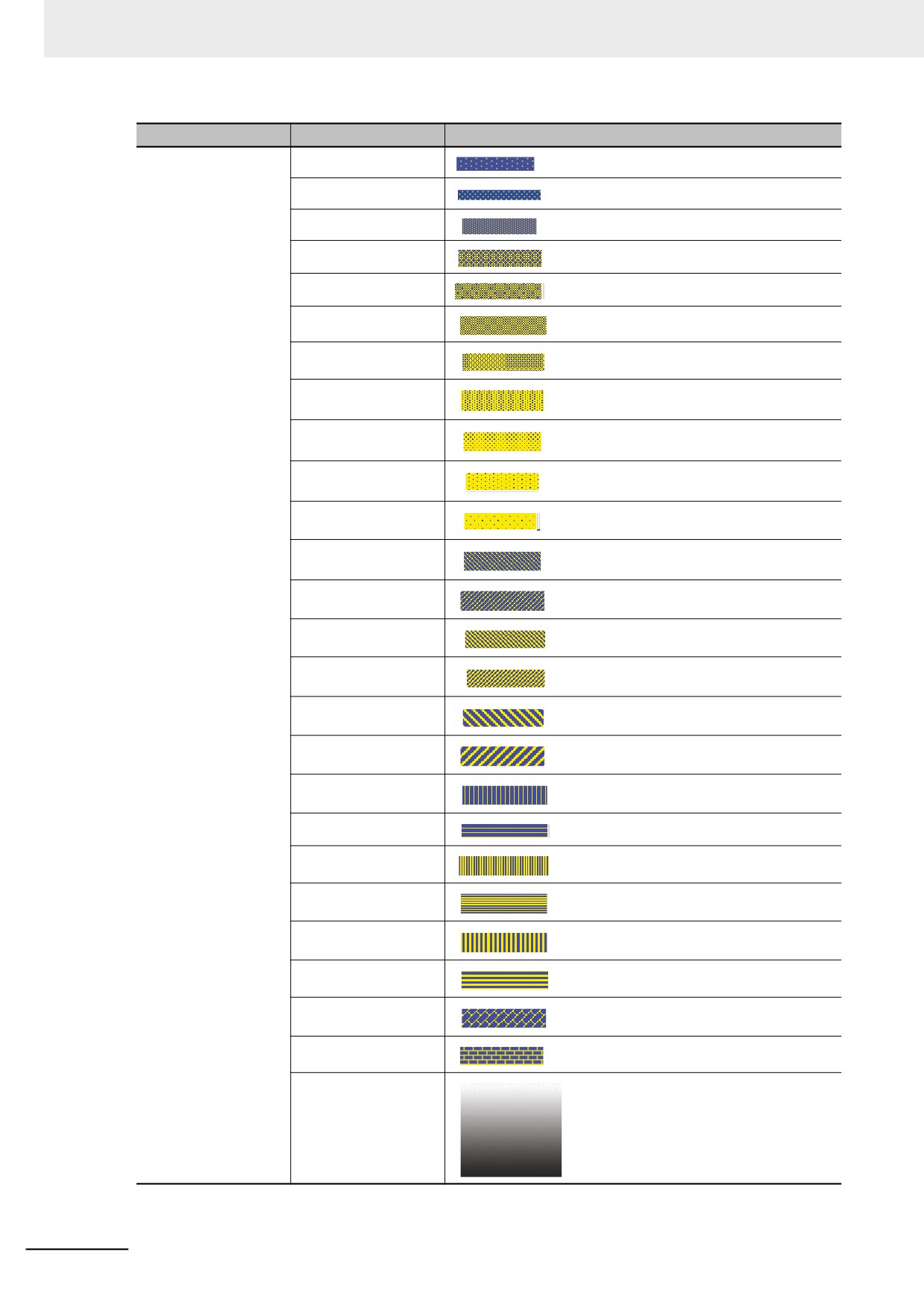
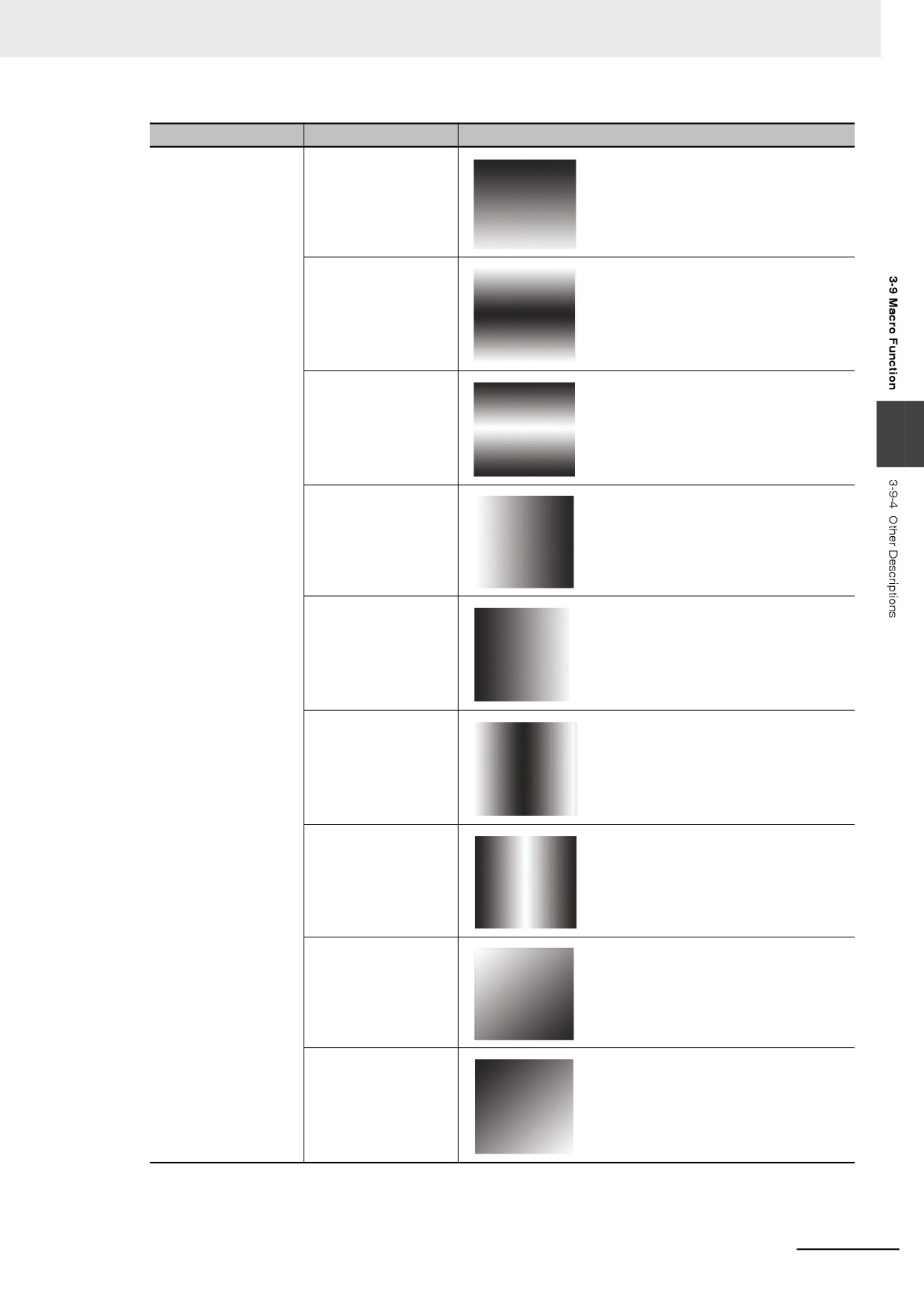
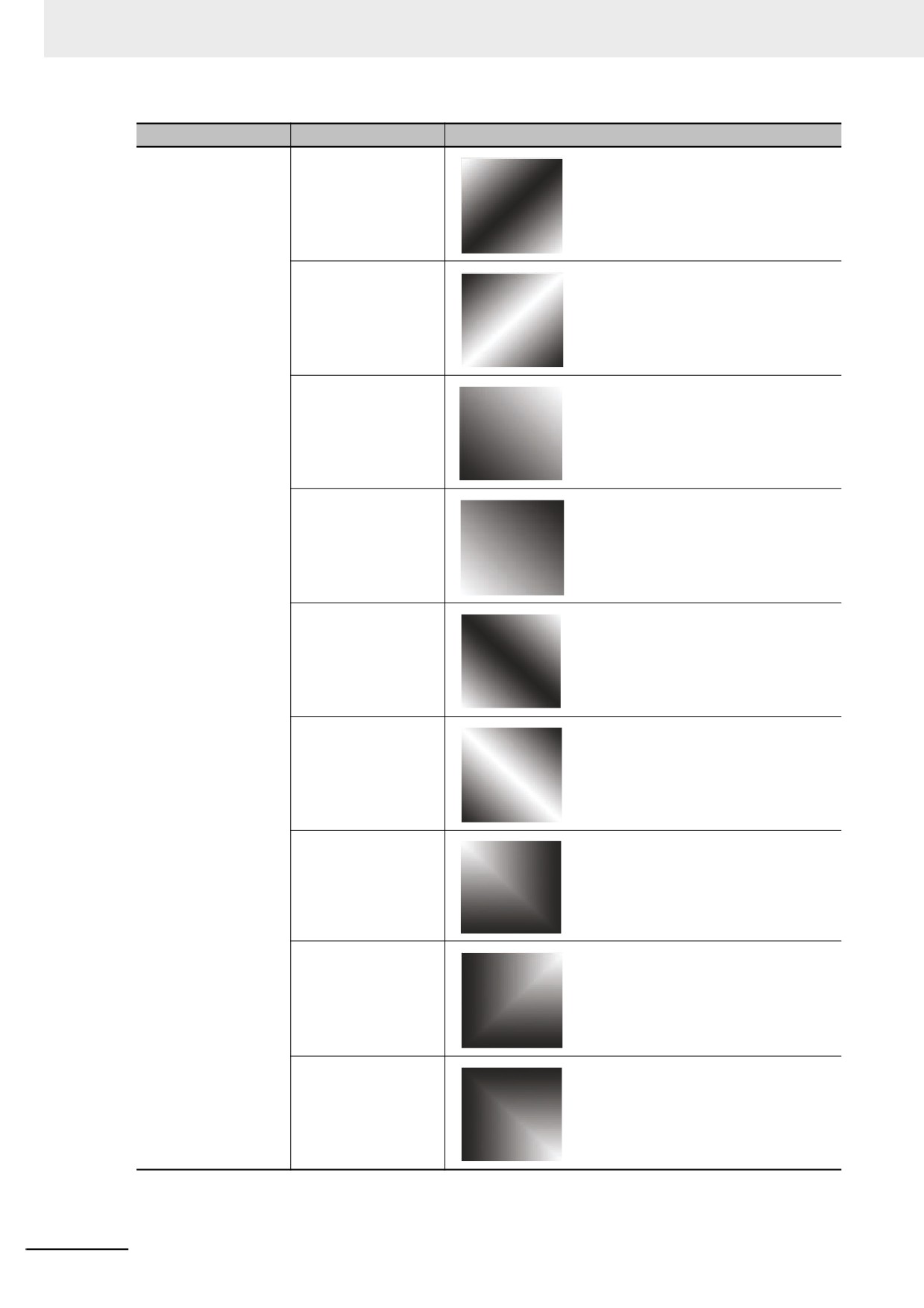
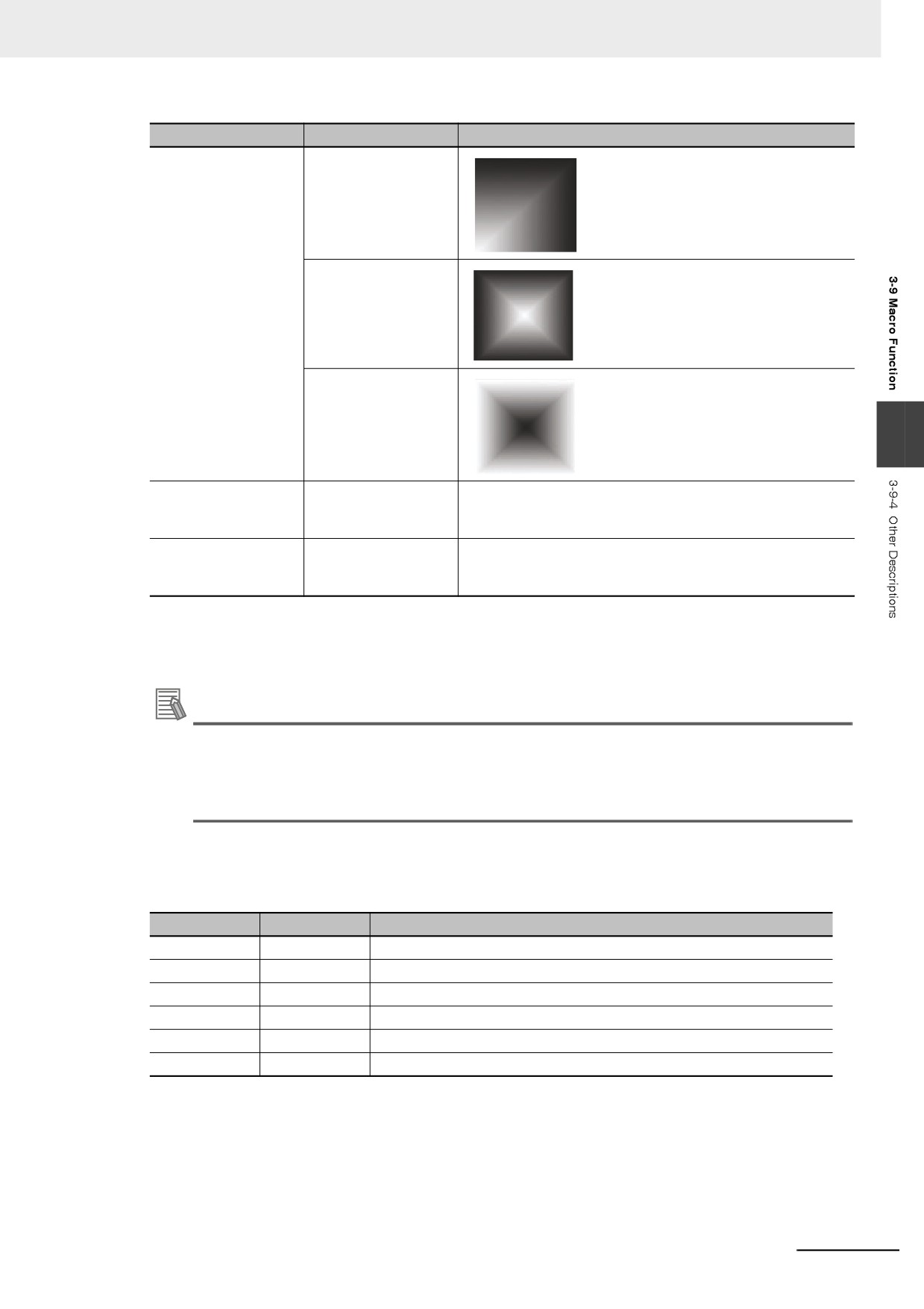
BrushParam is mainly used to set the type of the brush, the foreground color and
background color. Brush type is mainly used to set the filling styles used by the brush:
graphics-filling and gradient-filling. And the value range is as follows.
Parameter Name
Value
Descriptions
Type (Brush type)
BFS_NOBRUSH
No filling
BFS_SOLID
BFS_DENSE1
3-281
3 Functions of NB-Designer
Parameter Name
Value
Descriptions
BFS_DENSE2
BFS_DENSE3
BFS_DENSE4
BFS_DENSE5
BFS_DENSE6
BFS_DENSE7
BFS_DENSE8
BFS_DENSE9
BFS_DENSE10
BFS_DENSE11
BFS_DENSE12
BFS_FDIAG1
BFS_BDIAG1
BFS_FDIAG2
BFS_BDIAG2
BFS_FDIAG3
BFS_BDIAG3
BFS_VER1
BFS_HOR1
BFS_VER2
BFS_HOR2
BFS_VER3
BFS_HOR3
BFS_DIAGCROSS
BFS_CROSS
BFS_HORGRDT_FTTD
3-282
3 Functions of NB-Designer
Parameter Name
Value
Descriptions
BFS_HORGRDT_FDTT
BFS_HORGRDT_FETC
BFS_HORGRDT_FCTE
3
BFS_VERGRDT_FLTR
BFS_VERGRDT_FRTL
BFS_VERGRDT_FETC
BFS_VERGRDT_FCTE
BFS_OUPGRDT_FLTTRD
BFS_OUPGRDT_FRDTLT
3-283
3 Functions of NB-Designer
Parameter Name
Value
Descriptions
BFS_OUPGRDT_FETC
BFS_OUPGRDT_FCTE
BFS_ODWNGRDT_F
RTTLD
BFS_ODWNGRDT_F
LDTRT
BFS_ODWNGRDT_F
ETC
BFS_ODWNGRDT_F
CTE
BFS_CONGRDT_FLT
TRD
BFS_CONGRDT_FRT
TLD
BFS_CONGRDT_FR
DTLT
3-284
3 Functions of NB-Designer
Parameter Name
Value
Descriptions
BFS_CONGRDT_FLD
TRT
BFS_CENGRDT_FETC
BFS_CENGRDT_FCTE
3
ForeColor
0~65535
It is recommended to use Macro RGB (r. g. b) to set the color, and
(Pattern color)
the range for r, g and b is 0~255. The system will convert the value
of RGB (r, g, b) according to the color parameters of PT screen.
BackColor
0~65535
It is recommended to use Macro RGB (r. g. b) to set the color, and
(Background color)
the range for r, g and b is 0~255. The system will convert the value
of RGB (r, g, b) according to the color parameters of PT screen.
(c) Point Structure “Point”
The parameter of point structure is simpler: x represents the X-axis coordinate and y
represents the Y-axis coordinate for the point.
Additional Information
To specify the color with a RGB function, you need to specify r and b as a multiples of 8, and
specify g as a multiples of 4. The remainder will be rounded down.
If you specify 0 for r, g, and b, the transparent color is specified. To draw a black line, you need
to specify the value except 0 as you do for RGB (8, 0, 0).
(1) Drawing Function
(a) Rectangle “DrawRect (x, y, w, h, pen, brh)”
The description of the parameter is as follows:
Parameter
Type
Descriptions
x
Int.
X-axis coordinate of the upper-left corner of the rectangle (Unit: pixel)
y
Int.
Y-axis coordinate of the upper-left corner of the rectangle (Unit: pixel)
w
Int.
Rectangle width (Unit: pixel)
h
Int.
Rectangle height (Unit: pixel)
pen
PenParam
Rectangular-border pen
brh
BrushParam
Rectangular filling brush
3-285
3 Functions of NB-Designer
(b)
Rounded Rectangle “DrawRndRect (x, y, w, h, radius, pen, brh)”
The description of the parameter is as follows:
Parameter
Type
Descriptions
x
Int.
X-axis coordinate of the upper-left corner of the rectangle (Unit: pixel)
y
Int.
Y-axis coordinate of the upper-left corner of the rectangle (Unit: pixel)
w
Int.
Rectangle width (Unit: pixel)
h
Int.
Rectangle height (Unit: pixel)
radius
Int.
Rounded radius (Unit: pixel)
pen
PenParam
Rounded-rectangle-border brush
brh
BrushParam
Rounded-rectangle filling brush
(c)
Ellipse “DrawEclips (x, y, w, h, pen, brh)”
The description of the parameter is as follows:
Parameter
Type
Descriptions
x
Int.
X-axis coordinate of the upper-left corner of the circumscribed rectangle of ellipse (Unit: pixel)
y
Int.
Y-axis coordinate of the upper-left corner of the circumscribed rectangle of ellipse (Unit: pixel)
w
Int.
Width of the circumscribed rectangle of ellipse (Unit: pixel)
h
Int.
Height of the circumscribed rectangle of ellipse (Unit: pixel)
pen
PenParam
Ellipse-border pen
brh
BrushParam
Ellipse-filling brush
(d)
Line “DrawLine (x1, y1, x2, y2, pen)”
The description of the parameter is as follows:
Parameter
Type
Descriptions
x1
Int.
X-axis coordinate of line origin (Unit: pixel)
y1
Int.
Y-axis coordinate of line origin (Unit: pixel)
x2
Int.
X-axis coordinate of line end (Unit: pixel)
y2
Int.
Y-axis coordinate of line end (Unit: pixel)
pen
PenParam
Line brush
(e)
Polygon “DrawPolyg (pts, n, pen, brh)”
The description of the parameter is as follows:
Parameter
Type
Descriptions
pts
Point *
The first address of vertex-coordinate data for polygon
n
Int.
Vertex data of the polygon
pen
PenParam
Polygon-border pen
brh
BrushParam
Polygon-filling brush
(f)
Arc “DrawArc (x, y, w, h, start, end, pen)”
The description of the parameter is as follows:
Parameter
Type
Descriptions
x
Int.
X-axis coordinate of the upper-left corner of the circumscribed rectangle of arc (Unit: pixel)
y
Int.
Y-axis coordinate of the upper-left corner of the circumscribed rectangle of arc (Unit: pixel)
w
Int.
Width of the circumscribed rectangle of arc (Unit: pixel)
h
Int.
Height of the circumscribed rectangle of arc (Unit: pixel)
start
Int.
The starting angle of the arc (Unit: degree)
end
Int.
The end angle of the arc (Unit: degree)
pen
PenParam
Arc-border pen
3-286
3 Functions of NB-Designer
(g)
Sector “DrawPie (x, y, w, h, start, end, pen, brh)”
The description of the parameter is as follows:
Parameter
Type
Descriptions
x
Int.
X-axis coordinate of the upper-left corner of the circumscribed rectangle
of sector (Unit: pixel)
y
Int.
Y-axis coordinate of the upper-left corner of the circumscribed rectangle
of sector (Unit: pixel)
w
Int.
Width of the circumscribed rectangle of sector (Unit: pixel)
h
Int.
Height of the circumscribed rectangle of sector (Unit: pixel)
start
Int.
The starting angle of the sector (Unit: degree)
end
Int.
The end angle of the sector (Unit: degree)
pen
PenParam
Sector-border pen
brh
BrushParam
Sector-filling brush
3
For the drawing functions, RGB values can be used directly for the colors.
For the corresponding relationship between 65536 Color and RGB, the system will handle it directly.
int MacroEntry()
{
PenParam pen;
BrushParam brh;
Point pts[5];
short buf[2] = {0};
pts[0].x = 0;
pts[0].y = 0;
pts[1].x = 100;
pts[1].y = 0;
pts[2].x = 120;
pts[2].y = 150;
pen.type = 1;
pen.width = 0;
pen.color = RGB(0, 0, 0xFF);
brh.type = BFS_ODWNGRDT_FRTTLD;
brh.foreColor = RGB(0, 0, 0);
brh.backColor = RGB(255, 255, 255);
DrawRect(0, 0, 400, 400, pen, brh);
}
3-287
3 Functions of NB-Designer
7
Example of how to use the local variable functions
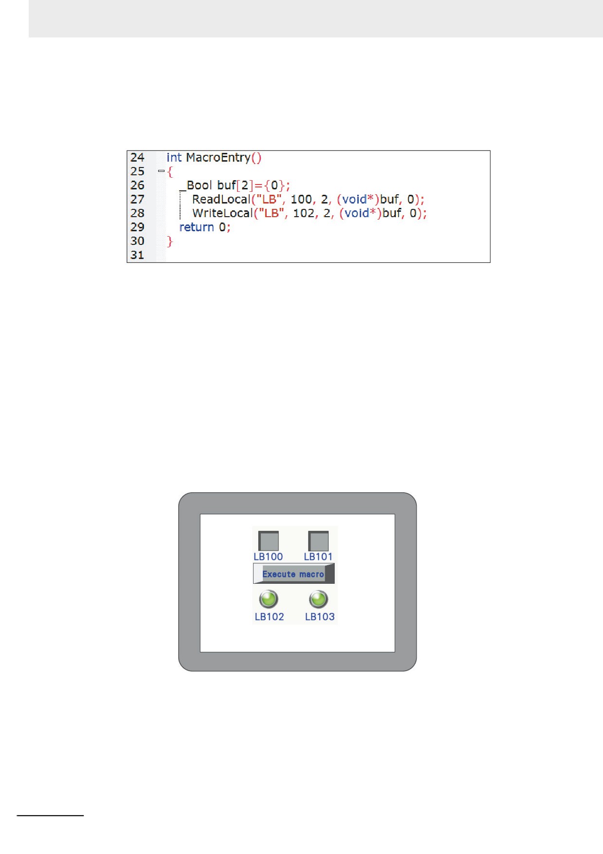
When the Macro is created as below, the variables read from the value LB100 and LB101 (in
the PT local memory) are written to LB102 and LB103 (in the PT local memory).
The codes are compiled as follows:
Where,
The “buf” is defined as “_Bool”, and it can also be defined as “short” because each bit address
in local LB memories occupies one-word (16 bit) space (but in fact only one bit in each word is
used.)
ReadLocal(“LB”, 100, 2, (void*)buf, 0) indicates that the values read from LB100 and LB101
are written to buf[0] and buf[1], respectively. “2” located in the center of the parenthesis
indicates the number of bit that the LB100 reads.
WriteLocal (“LB”, 102, 2, (void*)buf, 0) indicates that writes the read values to LB102 and
LB103, respectively.
Firstly, add 2 Bit Switch components with addresses of LB100 and LB101, and then add 2 Bit
Lamp components with addresses of LB102 and LB103. Finally, add a Function Key to execute
the Macro.
After the Save and Compile operations are performed, then execute the Macro:
After the LB100 and LB101 are turned ON, when the Macro is executed, you can see the
LB102 and LB103 are turned ON.
3-288
3 Functions of NB-Designer
8
Available standard functions
Following standard functions of C language is available. Refer to a commercial handbook of C
language for the details.
sin (double)
cos (double)
tan (double)
sinh (double)
cosh (double)
tanh (double)
asin (double)
acos (double)
atan (double)
3
atan2 (double, double)
exp (double)
log (double)
log10 (double)
pow (double, double)
sqrt (double)
ceil (double)
floor (double)
fabs (double)
ldexp (double, int)
frexp (double, int*)
modf (double, double*)
fmod (double, double)
isgreater(x, y)
isgreaterequal(x, y)
isless(x, y)
islessequal(x, y)
islessgreater(x, y)
isunordered(x, y)
3-289
3 Functions of NB-Designer
3-10 System Parameters
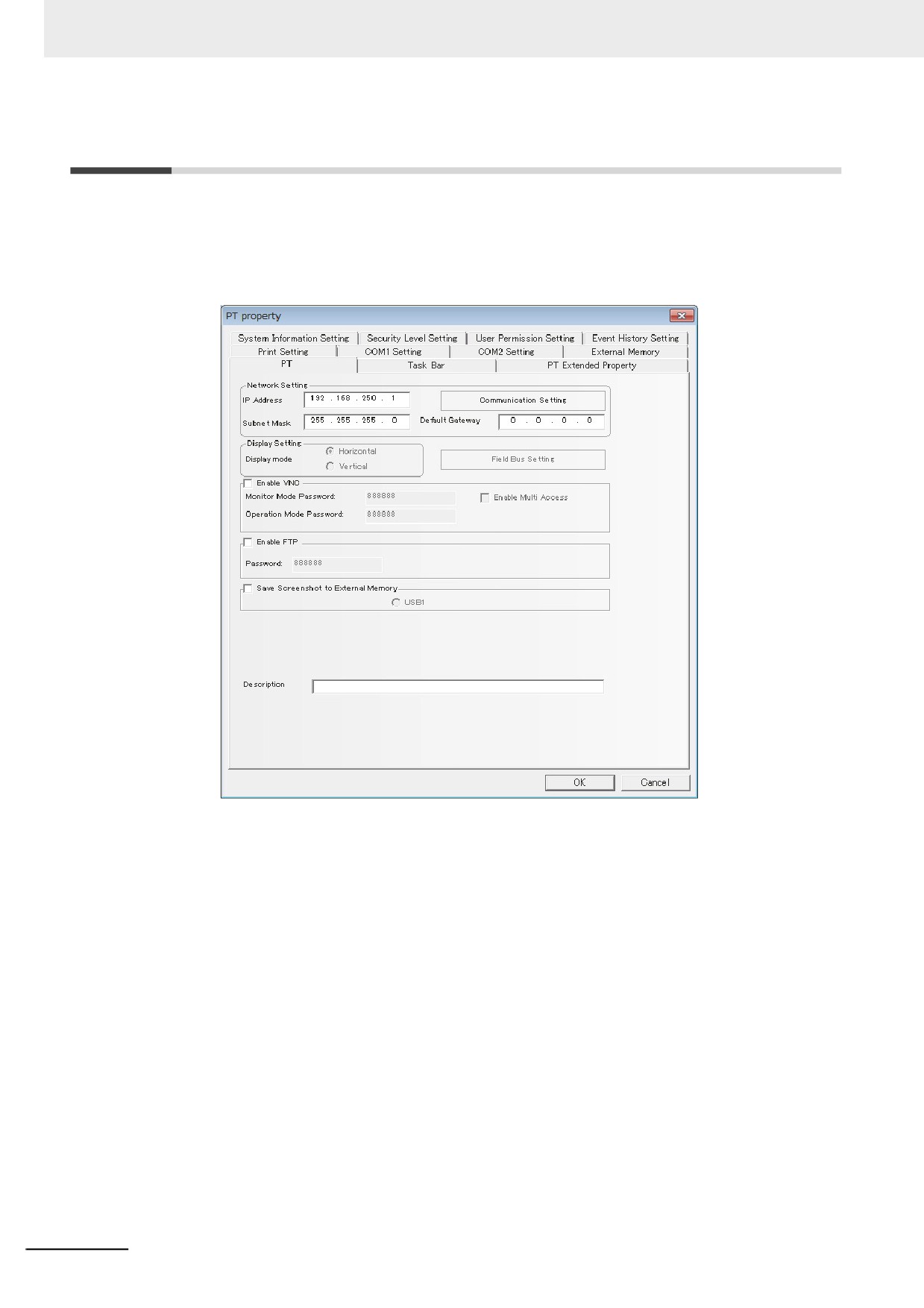
Specifications related to the NB units are performed in the PT Property.
The PT Property can specify the procedure to display the PT screens and the system specifications of
the PT units as well as the communications settings.
Double-clicking PT in Configuration and Setup Window can make system parameter dialog box pop up.
There are 11 tabs related to the communication: [PT], [Task Bar], [PT Extended Properties], [System
Information Setting], [User Permission Setting], [Security Level Setting], [Event History Setting], [Print
Setting], [COM1 Setting], [COM2 Setting], and [External Memory]. They will be described in the later
one by one.
3-290
3 Functions of NB-Designer
3-10-1
PT
3
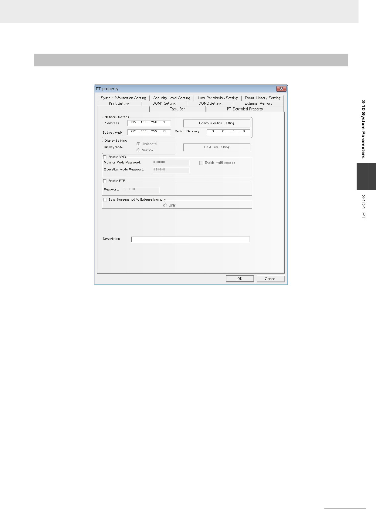
Network Setting: Refers to the network information such as IP Address, Subnet Mask, Default
Gateway and Display Setting etc.
Display Setting: Refers to the current display of PT (Horizontal or Vertical). Horizontal/Vertical display
is selected at dragging PT, once it is selected, it will not be switched again.
Enable VNC: Check the check box to enable VNC server function. VNC server status can be checked
by LB9290. Monitor mode and operation mode can be enabled/disabled by LB9291 -
LB9293.
Monitor Mode Password / Operation Mode Password:
For VNC server function, a password setting is required for monitor mode and operation
mode, respectively. The default is 888888. The password only supports the number
instead of the other characters. The password ranges from 0 to 4294967295.
Enable Multi Access: Check the check box to enable simultaneous multi client access. Simultaneous
access from multiple clients will deteriorate the performance of the NB. As a
preventive measure, check the load status on the processing and adjust the
load within the appropriate range when you use this option.
Enable FTP: Check the check box to enable FTP server function. For FTP server function, a password
setting is required. The default is 888888. The password only supports the number
instead of the other characters. The password ranges from 0 to 99999999.
Whether FTP server is enabled or disabled can be checked by LB9296.
Save Screen Shots to External Memory: Check the check box to save screen shots to the external
memory.
Description: Refers to the description for this PT. And the description will be displayed in PT
description box at the downloading and test etc., thus making the differentiation among
several PTs conveniently.
3-291
3 Functions of NB-Designer
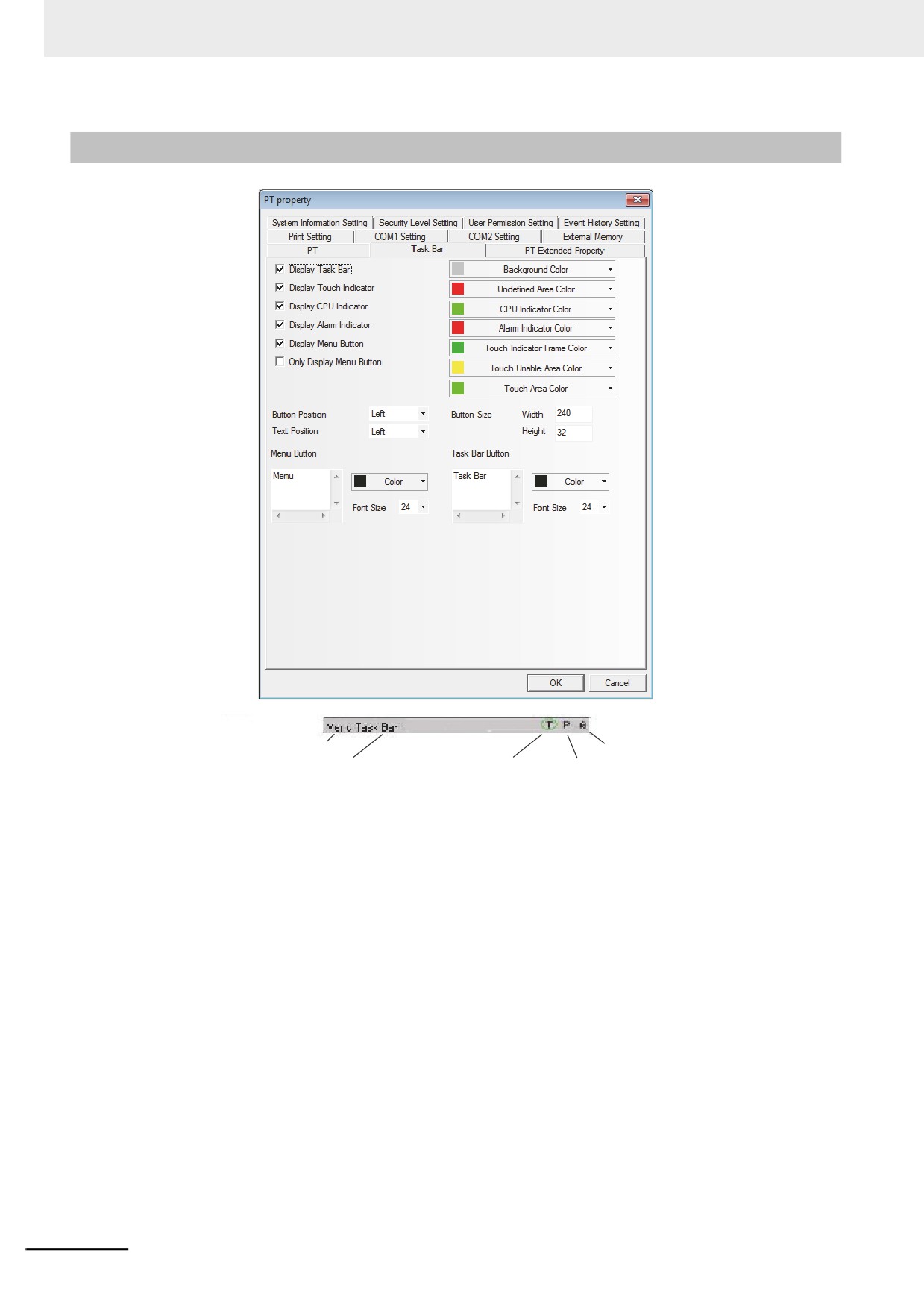
3-10-2
Task Bar
Menu Button
Alarm Indicator
Task Bar Button
Touch Indicator
CPU Indicator
Display Task Bar: Determines whether to display the task bar or not. If the “Display Task Bar” is
selected, the task bar as shown above will be displayed at the bottom of the screen.
Display Touch Indicator: When the screen is touched, the touch indicator will change the color. If the
“Display Touch Indicator” is checked, the touch indicator will be displayed at
the right side of the task bar, as shown above. (The touch indicator is
expressed by “T” in simulator and the PT.)
Display CPU Indicator: CPU Indicator is a Level Meter showing the usage condition of CPU in
percentage form. If “Display CPU Indicator” is checked, CPU Indicator will be
displayed at the right side of the task bar, as shown above. (The CPU
Indicator is expressed by “P” in simulator and the PT.)
Display Alarm Indicator: Alarm Indicator is a Level Meter showing the ratio of the current alarm
numbers to the total alarm numbers logged in the alarm information. If
“Display Alarm Indicator” is checked, Alarm Indicator will be displayed at the
right side of the task bar, as shown above. (The alarm indicating lamp is
expressed by “A” in simulator and the PT.)
The Alarm Indicator is the bar to display the number in percentage which
divides the total number of the alarm the registered to Alarm Settings with
the number of the alarm currently occurring.
Display Menu Button: After this option is checked, you can use the Menu Screen. If this option isn't
checked, the Menu Screen will not pop up.
Only Show Menu Button: After this option is checked, only the Menu Screen button is displayed in the
task bar.
3-292