OMRON NB-Designer OPERATION MANUAL (NB-series, 2020) - page 1
Cat. No. V106-E1-22
NB-series
NB3Q-TWB
NB5Q-TWB
NB7W-TWB
NB10W-TW01B
Programmable Terminals
NB-Designer
OPERATION MANUAL
Introduction
Introduction
Thank you for purchasing an NB-series Programmable Terminal.
NB-Series Programmable Terminals (PTs) are designed to handle information generated in FA
production sites. Be sure to understand the functions and performances etc thoroughly before using PT
correctly.
Intended Audience
This manual is intended for the following personnel, who must also have knowledge of electrical
systems (an electrical engineer or the equivalent).
• Personnel in charge of introducing FA systems into production facilities.
• Personnel in charge of designing FA systems.
• Personnel in charge of installing and connecting FA facilities.
• Personnel in charge of managing FA systems and facilities
General Precautions
• The user must operate the product according to the performance specifications described in the
operation manuals.
• Do not use the PT touch switch input functions for applications where danger to human life or serious
property damage is possible, or for emergency switch applications.
• Before using the product under conditions which are not described in the manual or applying the
product to nuclear control systems, railroad systems, aviation systems, vehicles, combustion
systems, medical equipment, amusement machines, safety equipment, and other systems,
machines and equipment that may have a serious influence on lives and property if used improperly,
consult your OMRON representative.
• Make sure that the ratings and performance characteristics of the product are sufficient for the
systems, machines, and equipment, and be sure to provide the systems, machines, and equipment
with double safety mechanisms.
• This manual provides information for connecting and setting up an NB-Series PT. Be sure to read
this manual before attempting to use the PT and keep this manual close at hand for reference during
installation and operation.
1
NB-series Manuals
NB-series Manuals
NB-series manuals are organized in the sections listed in the following tables. Refer to the appropriate
section in the manuals as required.
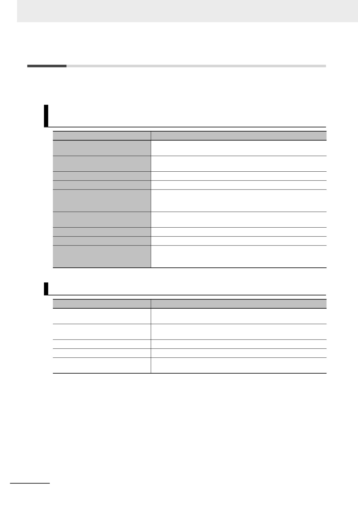
Programmable Terminals NB-Designer Operation Manual
(Cat. No. V106) (This manual)
Section
Contents
Section 1 Introduction
This section provides an outline of the NB-series PTs, including their
functions, features, connection types and communication methods.
Section 2 Installation and Startup of
This section describes how to install and start the NB-Designer.
NB-Designer
Section 3 Functions of NB-Designer
This section describes the functions of NB-Designer.
Section 4 Functions of NBManager
This section describes the functions of NBManager.
Section 5 Maintenance and
This section describes the maintenance and check to prevent the
Abnormality Handling
abnormality occurrence and the handling of the abnormalities occurred
in NB Unit.
Section 6 Functions Related to
This section describes the functions related to external memory.
External Memory
Section 7 PictBridge Printing
This section describes the PictBridge printing function.
Section 8 Web Interface
This section describes the Web Interface function.
Appendices
The appendices provide lists of the NB Units, the Communication Units,
the applicable PLCs, the memories sapported by PLC, and the list of
NB-Designer functions.
Programmable Terminals Setup Manual (Cat. No. V107)
Section
Contents
Section 1 Part Names and Functions
This section describes the names and functions of the various parts of
an NB Unit.
Section 2 Installing the NB Unit and
This section describes the methods used to install the NB Unit and
Connecting Peripheral Devices
connect peripheral devices.
Section 3 System Setting Mode
This section describes the System Setting Mode.
Section 4 Calibrate Mode
This section describes the Calibrate Mode.
Appendices
The appendices provide information on specifications, dimensions,
wirings, and lists of the NB Units, the applicable PLCs and options.
2
NB-series Manuals
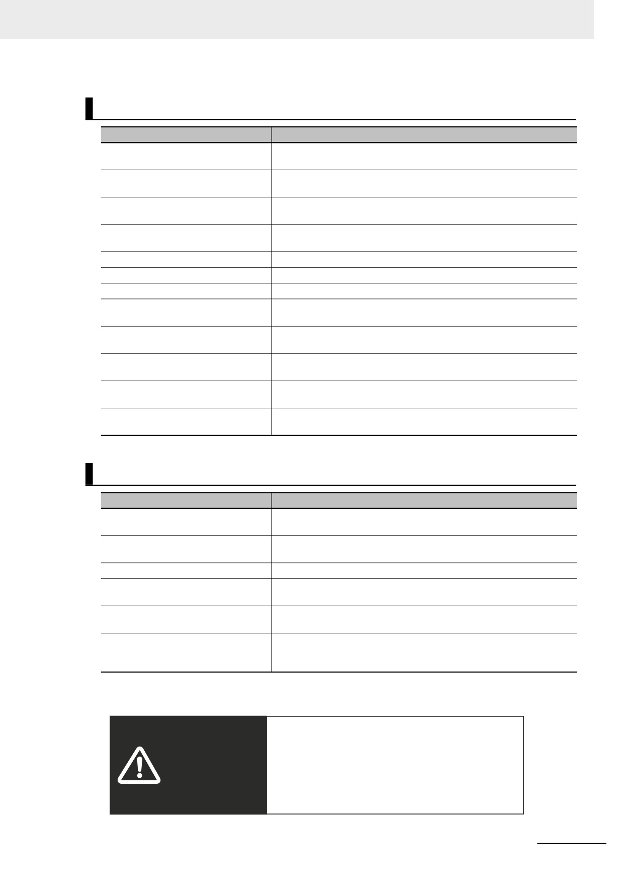
Programmable Terminals Host Connection Manual (Cat. No. V108)
Section
Contents
Section 1 List for All PLCs
This section lists all PLCs supported by NB Units.
Supported by NB series
Section 2 Connecting to SIEMENS
This section describes the connection to SIEMENS PLCs.
PLCs
Section 3 Connecting to Mitsubishi
This section describes the connection to Mitsubishi PLCs.
PLCs
Section 4 Connecting to Schneider
This section describes the connection to Schneider PLCs.
PLCs
Section 5 Modbus Connection
This section describes the connection on Modbus protocol.
Section 6 Connecting to Delta PLCs
This section describes the connection to Delta PLCs.
Section 7 Connecting to LG PLCs
This section describes the connection to LG PLCs.
Section 8 Connecting to Panasonic
This section describes the connection to Panasonic PLCs.
PLCs
Section 9 Connecting to Allen-
This section describes the connection to Allen-Bradley PLC.
Bradley (Rockwell) PLC
Section 10 Connecting to PLC of GE
This section describes the connection to PLC of GE Fanuc Automation
Fanuc Automation Inc.
Inc.
Section 11 Connecting to Keyence
This section describes the connection to Keyence PLCs.
PLCs
Section 12 Connecting to OMRON
This section describes the connection to OMRON Safety Controller.
Safety Controller
Programmable Terminals Startup Guide Manual (Cat. No. V109)
Section
Contents
Section 1 NB Overview
This section provide specifications of the NB Unit, describes its names
and functions of the various parts.
Section 2 System Design
This section describes the manual structure, takes NB7W as an
example to introduce the operation procedures of the NB system.
Section 3 Installation and Wiring
This section describes how to install and wire the NB Unit.
Section 4 Screen Creation
This section describes how to create a demonstration project through
NB-Designer.
Section 5 Run
This section describes how to start running at the Host side and prepare
to send screen data to NB7W.
Section 6 Maintenance and
This section describes the maintenance and inspection methods for
Troubleshooting
preventing errors occurring, and troubleshooting measures when errors
occur.
Failure to read and understand the information
provided in this manual may result in personal injury
or death, damage to the product, or product failure.
Please read each section in its entirety and be sure
WARNING
you understand the information provided in the
section and related sections before attempting any
of the procedures or operations given.
3
Manual Structure
Manual Structure
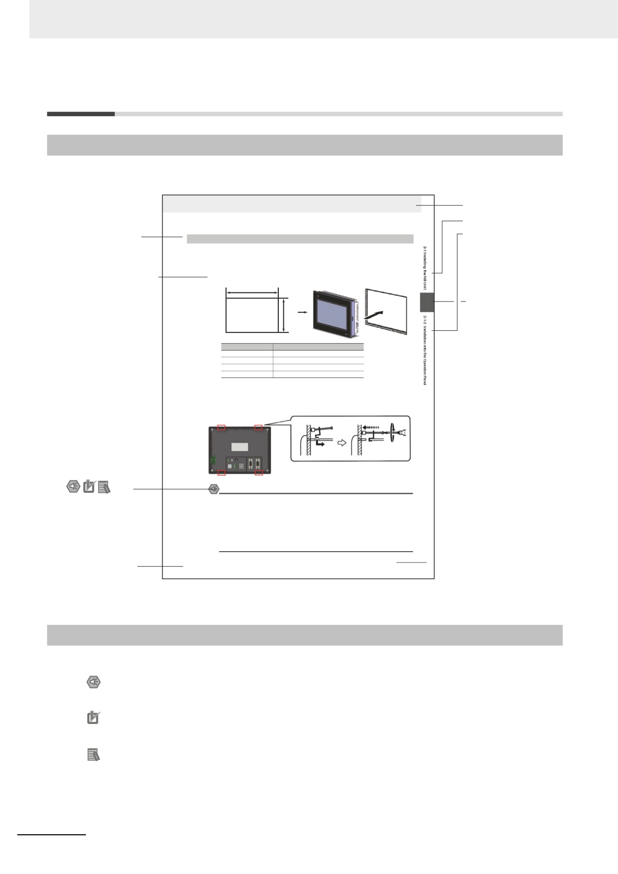
Page Structure and Icons
The following page structure and icons are used in this manual.
2 Installing the NB Unit and Connecting Peripheral Devices
Level 1 heading
Level 2 heading
Level 3 heading
2-1-2
Installation onto the Operation Panel
Level 3 heading
Install the NB Unit by embedding it into the operation panel.
Gives the current
Use the metal kit and tool (a crosshead screwdriver) supplied with the Unit for installation.
headings.
Proceed the installation following the procedures below.
Step in a procedure
1 Panel cutout with dimensions is shown below. Fit the NB Unit into the panel from the front side.
Indicates a step in a
Width
procedure.
2
Page tab
Opening dimensions
Height
Gives the number
of the section.
Models
Opening Dimension (W H mm)
NB3Q-TW00B/TW01B
119.0(+0.5/-0)
93.0(+0.5/-0)
NB5Q-TW00B/TW01B
172.4(+0.5/-0)
131.0(+0.5/-0)
NB7W-TW00B/TW01B
191.0(+0.5/-0)
137.0(+0.5/-0)
NB10W-TW01B
258.0(+0.5/-0)
200.0(+0.5/-0)
2 As follows, insert panel fixators at the locations indicated by red box around the back of the NB Unit.
Insert the hooks of positioners into the square holes on the Unit to hold the fixators properly, and
tighten the screws firmly with the screwdriver.
NB5Q/NB7W-TWB
Special Information
(See below.)
Icons are used to indicate
precautions and
additional information.
Precautions for Safe Use
• When operating on the operation panel, make sure to keep metal particles from entering the
Unit.
The mounting panel must be between 1.6 and 4.8 mm thick. The NB Unit must be installed
in a control panel.
For the sake of waterproof and dustproof, all the fixators must be evenly tightened to a
torque of 0.5~0.6 Nm. If the tightening torque exceeds the specified value, or the tightening
is not even, deformation of the front panel may occur.
Make sure that the operation panel is clean, unbent, and strong enough for the installation
process.
Manual name
NB-series Programmable Terminals Setup Manual(V107)
2-3
This illustration is provided only as a sample and may not literally appear in this manual.
Special Information
Special information in this manual is classified as follows:
Precautions for Safe Use
Precautions on what to do and what not to do to ensure using the product safely.
Precautions for Correct Use
Precautions on what to do and what not to do to ensure proper operation and performance.
Additional Information
Additional information to increase understanding or make operation easier.
4
Terminology
Terminology
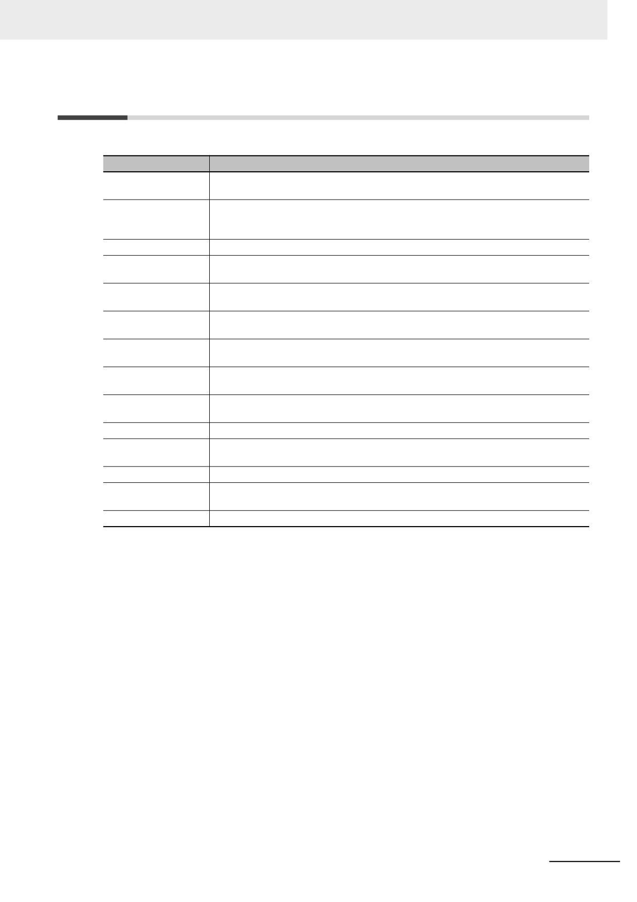
The following terminology is used in this manual.
Terms
Descriptions
NB Unit
Indicates the main Unit of the products in the OMRON NB Series of Programmable
Terminal.
NB Series
Indicates products in the OMRON NB Series of Programmable Terminal.
In this manual, unless otherwise specified, NB Series is taken as the subject
concerned.
PLC
Indicates a Programmable Controller.
CP Series
Indicates the following products in the OMRON CP Series of Programmable
Controllers: CP1H, CP1L, CP1E, CP2E
CS/CJ Series
Indicates the following products in the OMRON CS/CJ Series of Programmable
Controllers: CS1G, CS1H, CS1G-H, CS1H-H, CJ1G, CJ1M, CJ2M, CJ2H
NJ/NX Series
Indicates the following OMRON SYSMAC NJ/NX Series of Programmable Controllers:
NJ501, NJ301, NJ101, NX102, NX1P2
C Series
Indicates the following products in the OMRON C Series of Programmable Controllers:
C200HX(-Z), C200HG(-Z), C200HE(-Z), CQM1, CQM1H, CPM1A, CPM2A, CPM2C
Serial Communication
Indicates a Serial Communication Unit for an OMRON SYSMAC CS/CJ-Series PLC.
Unit
Serial Communication
Indicates a Serial Communication Board for an OMRON SYSMAC CS/CJ-Series PLC.
Board
Communication Board
Indicates a Communication Board for an OMRON C200HX/HG/HE(-Z) PLC.
CPU Unit
Indicates a CPU Unit in the OMRON CP, CS/CJ or SYSMAC C Series of
Programmable Controllers.
NB-Designer
Indicates the OMRON NB-Designer.
Host
Indicates the PLC and other units functioning as the control devices for NB-Series
Units.
PT
Indicates an OMRON Programmable Terminal.
5
CONTENTS
CONTENTS
Introduction
1
NB-series Manuals
2
Manual Structure
4
Terminology
5
Terms and Conditions Agreement
13
Safety Precautions
15
Precautions for Safe Use
18
Precautions for Correct Use
20
Conformance to EC Directives
21
Related Manuals
22
Sec. 1
Introduction
1-1
1-1
Functions and Structure of NB-Series PTs
1-2
1-1-1
How NB-Series PTs Work at FA Production Sites
1-2
1-1-2
Operations of NB-Series PTs
1-2
1-2
Communicating with the Host
1-4
1-2-1
What’s the Host Link?
1-4
1-2-2
Connecting Methods
1-5
1-2-3
Communicating with the PLC Manufactured by Other Companies
1-6
1-3
System Configuration
1-7
1-3-1
Connectable Peripheral Devices
1-7
1-4
Procedures for NB-Series PTs’ Operation
1-8
Sec. 2
Installation and Startup of NB-Designer
2-1
2-1
Before Installation
2-2
2-2
Installation/Uninstallation
2-3
2-2-1
Installation Procedure
2-3
2-2-2
Uninstallation Procedure
2-3
2-3
Startup & Quit
2-4
2-3-1
Starting Method
2-4
2-3-2
Quitting Method
2-4
2-4
Installation of USB Driver for NB
2-5
Sec. 3
Functions of NB-Designer
3-1
3-1
User Screen
3-4
3-2
Menus
3-7
3-2-1
File Menu
3-7
3-2-2
Edit Menu
3-11
3-2-3
View Menu
3-16
7
CONTENTS
3-2-4
Screen Menu
3-27
3-2-5
Draw Menu
3-31
3-2-6
Components Menu
3-31
3-2-7
Tools Menu
3-32
3-2-8
Option Menu
3-32
3-2-9
Window Menu
3-33
3-2-10
Help Menu
3-34
3-3
NB-Designer Software Window
3-35
3-3-1
Project Library Window
3-35
3-3-2
Project File Window
3-39
3-3-3
Project Work Space
3-39
3-3-4
Output Window
3-45
3-3-5
Component List Window
3-46
3-4
Screen Concept
3-47
3-4-1
Screen Types
3-47
3-4-2
Screen Property
3-50
3-4-3
Screen Creation
3-54
3-4-4
Screen Opening
3-54
3-4-5
Screen Deletion
3-55
3-4-6
Components Related to Screen
3-55
3-5
Basic Design Method
3-56
3-5-1
Designing Components
3-56
3-5-2
About ID No
3-57
3-5-3
Additional Comments (Descriptions)
3-58
3-5-4
Read/Write Address for PLC
3-59
3-5-5
Vector Graphic
3-60
3-5-6
Bitmap
3-65
3-5-7
Creating Label
3-68
3-5-8
Task Bar and Operation Buttons
3-70
3-5-9
Fonts
3-72
3-5-10
Basic Properties of Component
3-75
3-5-11
Control Setting of Component
3-76
3-5-12
Display Setting of Component
3-80
3-6
Parts
3-82
3-6-1
Bit Button
3-82
3-6-2
Bit Lamp
3-85
3-6-3
Bit Switch
3-88
3-6-4
Command Button
3-89
3-6-5
Word Lamp
3-96
3-6-6
Word Switch
3-98
3-6-7
XY Graph
3-102
3-6-8
Moving Component
3-111
3-6-9
Animation
3-116
3-6-10
Number Input
3-118
3-6-11
Number Display
3-124
3-6-12
Text Input
3-127
3-6-13
Text Display
3-131
3-6-14
Level Meter
3-132
3-6-15
Analog Meter
3-143
3-6-16
Indirect Screen
3-147
3-6-17
Direct Screen
3-150
8
CONTENTS
3-6-18
Alarm
3-152
3-6-19
Data Log
3-154
3-6-20
Recipe
3-164
3-6-21
Oscillograph
3-164
3-6-22
Scroll Bar
3-168
3-6-23
Event
3-171
3-6-24
Note Book
3-178
3-6-25
Word Neon Lamp
3-189
3-6-26
Bit Neon Lamp
3-190
3-6-27
Touch Trigger
3-191
3-6-28
Table
3-193
3-6-29
Data History
3-194
3-7
Function Parts
3-200
3-7-1
Scale
3-200
3-7-2
Function Key
3-201
3-7-3
Alarm Display
3-209
3-7-4
Timer
3-213
3-7-5
Bitmap
3-218
3-7-6
Vector Graphics
3-219
3-7-7
Notepad
3-220
3-7-8
Data Transmission
3-223
3-7-9
Freeplotting
3-226
3-7-10
Date/Time
3-227
3-7-11
Indirect Shape
3-229
3-7-12
User Information
3-233
3-7-13
Multifunction
3-233
3-7-14
Event Display
3-236
3-8
Project Database
3-238
3-8-1
Text Library
3-238
3-8-2
Variable Table
3-244
3-8-3
Alarm Setting
3-248
3-8-4
Event Setting
3-253
3-8-5
PLC Control
3-257
3-9
Macro Function
3-265
3-9-1
Create a Simple Macro Program
3-265
3-9-2
Macro and Specification of Operation with Read/Write Variables
3-272
3-9-3
Macro Triggering
3-273
3-9-4
Other Descriptions
3-276
3-10
System Parameters
3-290
3-10-1
PT
3-291
3-10-2
Task Bar
3-292
3-10-3
PT Extended Properties
3-294
3-10-4
System Information Setting
3-304
3-10-5
Security Levels Setting
3-306
3-10-6
User Permission Setting
3-308
3-10-7
Event History Setting
3-322
3-10-8
COM1/COM2 Setting
3-324
3-10-9
External Memory
3-325
3-10-10
Ethernet Communication Setting
3-327
9
CONTENTS
3-11 Address of System Memory
3-328
3-11-1
Local Bit (LB)
3-329
3-11-2
Local Word (LW)
3-334
3-11-3
Nonvolatile Local Word (LW10000~10255)
3-339
3-11-4
System Information Table
3-341
3-12 Recipe Data
3-343
3-12-1
Process of Creating One Recipe Component
3-343
3-12-2
Recipe Memory
3-345
3-12-3
Upload/Download of Recipe Data between PT and PLC
3-349
3-13 Security Level
3-354
3-14 Test
3-360
3-14-1
Offline test
3-360
3-14-2
Direct Online test
3-361
3-14-3
Indirect Online test
3-362
3-15 Download
3-363
3-15-1
Transmission Setting
3-363
3-15-2
Download via USB Memory
3-366
3-15-3
Download to USB1
3-366
3-15-4
Specification of Downloading Contents
3-366
3-16 Other Functions
3-371
3-17 RecipeEditor
3-421
Sec. 4
Functions of NBManager
4-1
4-1
Introduction of NBManager
4-2
4-2
Download Operation
4-3
4-2-1
Communication Setting
4-3
4-2-2
Select Data
4-6
4-2-3
LOGO Setting
4-9
4-2-4
Clear Data
4-10
4-3
Upload Operation
4-12
4-4
System Operation
4-15
4-5
Get Version
4-16
4-6
Decompile Operation
4-17
4-7
Pass Through Communication
4-18
4-8
Web Interface Operation
4-20
Sec. 5
Maintenance and Abnormality Handling
5-1
5-1
Maintenance
5-2
5-2
Checking and Cleaning
5-4
5-3
Abnormality Handling
5-6
5-4
Unit Replacement Precautions
5-10
10
CONTENTS
Sec. 6
Functions Related to External Memory
6-1
6-1
Components Related to External Memory
6-2
6-1-1
Function Key
6-2
6-1-2
Event, Event History Display and Event Display
6-5
6-1-3
Data History, Data Log and XY Graph
6-7
6-1-4
Operation Log
6-8
6-1-5
Recipe Data
6-11
6-1-6
CSV Import / Export
6-12
6-1-7
PLC Control
6-13
6-1-8
File List
6-14
6-1-9
FTP Server
6-15
Sec. 7
PictBridge Printing
7-1
7-1
PictBridge Function
7-2
7-2
Setting Method for Using Printing Function
7-4
7-3
Components Related to Printing and Setup Descriptions
7-6
7-3-1
PLC Control
7-6
7-4
List of System memories Related to Printing
7-8
7-5
List of Error Codes for Printing
7-9
7-6
Recommended Printer Models
7-10
Sec. 8
Web Interface
8-1
8-1
Defining Web Interface
8-2
8-2
Setup Web Interface on a PC
8-3
8-3
Connection Method and Each Page Function
8-4
8-4
URL List
8-10
Sec. A
Appendices
A-1
A-1
List of Models
A-2
A-2
NB-Designer Function List
A-6
A-3
List of memories supported by OMRON PLC
A-11
A-4
Usage of Forced Address Bit
A-16
Revision History
1
11
Terms and Conditions Agreement
Terms and Conditions Agreement
Warranty, Limitations of Liability
Warranties
z
Exclusive Warranty
Omron’s exclusive warranty is that the Products will be free from defects in materials and workman-
ship for a period of twelve months from the date of sale by Omron (or such other period expressed in
writing by Omron). Omron disclaims all other warranties, express or implied.
z
Limitations
OMRON MAKES NO WARRANTY OR REPRESENTATION, EXPRESS OR IMPLIED, ABOUT
NON-INFRINGEMENT, MERCHANTABILITY OR FITNESS FOR A PARTICULAR PURPOSE OF
THE PRODUCTS. BUYER ACKNOWLEDGES THAT IT ALONE HAS DETERMINED THAT THE
PRODUCTS WILL SUITABLY MEET THE REQUIREMENTS OF THEIR INTENDED USE.
Omron further disclaims all warranties and responsibility of any type for claims or expenses based
on infringement by the Products or otherwise of any intellectual property right.
z
Buyer Remedy
Omron’s sole obligation hereunder shall be, at Omron’s election, to (i) replace (in the form originally
shipped with Buyer responsible for labor charges for removal or replacement thereof) the non-com-
plying Product, (ii) repair the non-complying Product, or (iii) repay or credit Buyer an amount equal
to the purchase price of the non-complying Product; provided that in no event shall Omron be
responsible for warranty, repair, indemnity or any other claims or expenses regarding the Products
unless Omron’s analysis confirms that the Products were properly handled, stored, installed and
maintained and not subject to contamination, abuse, misuse or inappropriate modification. Return of
any Products by Buyer must be approved in writing by Omron before shipment. Omron Companies
shall not be liable for the suitability or unsuitability or the results from the use of Products in combi-
nation with any electrical or electronic components, circuits, system assemblies or any other materi-
als or substances or environments. Any advice, recommendations or information given orally or in
writing, are not to be construed as an amendment or addition to the above warranty.
See http://www.omron.com/global/ or contact your Omron representative for published information.
Limitation on Liability; Etc
OMRON COMPANIES SHALL NOT BE LIABLE FOR SPECIAL, INDIRECT, INCIDENTAL, OR
CONSEQUENTIAL DAMAGES, LOSS OF PROFITS OR PRODUCTION OR COMMERCIAL LOSS
IN ANY WAY CONNECTED WITH THE PRODUCTS, WHETHER SUCH CLAIM IS BASED IN
CONTRACT, WARRANTY, NEGLIGENCE OR STRICT LIABILITY.
Further, in no event shall liability of Omron Companies exceed the individual price of the Product on
which liability is asserted.
13
Terms and Conditions Agreement
Suitability of Use
Omron Companies shall not be responsible for conformity with any standards, codes or regulations
which apply to the combination of the Product in the Buyer's application or use of the Product. At
Buyer's request, Omron will provide applicable third party certification documents identifying ratings
and limitations of use which apply to the Product. This information by itself is not sufficient for a com-
plete determination of the suitability of the Product in combination with the end product, machine,
system, or other application or use. Buyer shall be solely responsible for determining appropriate-
ness of the particular Product with respect to Buyer's application, product or system. Buyer shall
take application responsibility in all cases.
NEVER USE THE PRODUCT FOR AN APPLICATION INVOLVING SERIOUS RISK TO LIFE OR
PROPERTY OR IN LARGE QUANTITIES WITHOUT ENSURING THAT THE SYSTEM AS A
WHOLE HAS BEEN DESIGNED TO ADDRESS THE RISKS, AND THAT THE OMRON PROD-
UCT(S) IS PROPERLY RATED AND INSTALLED FOR THE INTENDED USE WITHIN THE OVER-
ALL EQUIPMENT OR SYSTEM.
Programmable Products
Omron Companies shall not be responsible for the user's programming of a programmable Product,
or any consequence thereof.
Disclaimers
Performance Data
Data presented in Omron Company websites, catalogs and other materials is provided as a guide
for the user in determining suitability and does not constitute a warranty. It may represent the result
of Omron's test conditions, and the user must correlate it to actual application requirements. Actual
performance is subject to the Omron's Warranty and Limitations of Liability.
Change in Specifications
Product specifications and accessories may be changed at any time based on improvements and
other reasons. It is our practice to change part numbers when published ratings or features are
changed, or when significant construction changes are made. However, some specifications of the
Product may be changed without any notice. When in doubt, special part numbers may be assigned
to fix or establish key specifications for your application. Please consult with your Omron's represen-
tative at any time to confirm actual specifications of purchased Product.
Errors and Omissions
Information presented by Omron Companies has been checked and is believed to be accurate;
however, no responsibility is assumed for clerical, typographical or proofreading errors or omissions.
14
Safety Precautions
Safety Precautions
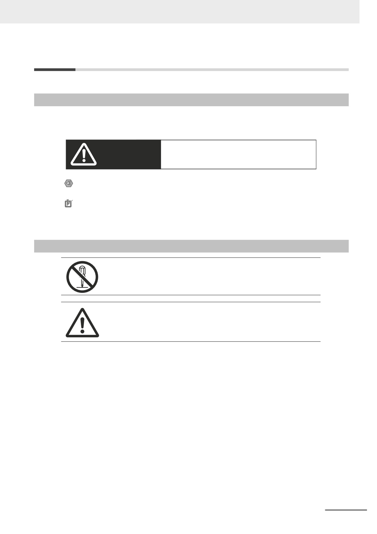
Notation Used for Safety Information
The following notation is used in this manual to provide precautions required to ensure safe usage of
the product. The safety precautions that are provided are extremely important to safety. Always read
and heed the information provided in all safety precautions.
Indicates an imminently hazardous situation which,
if not avoided, will result in death or serious injury.
WARNING
Additionally, there may be severe property damage.
Precautions for Safe Use
Indicates precautions on what to do and what not to do to ensure using the product safely.
Precautions for Correct Use
Indicates precautions on what to do and what not to do to ensure proper operation
and performance.
Note Indicates suggestive information and precautions on operation of the product.
Symbols
The circle and slash symbol indicates operations that you must not do.
The specific operation is shown in the circle and explained in text.
This example indicates prohibiting disassembly.
The triangle symbol indicates precautions (including warnings).
The specific operation is shown in the triangle and explained in text.
This example indicates a general precaution.
15

Safety Precautions
WARNING
Do not attempt to take the product apart and do not touch the product inside while the
power is being supplied. Otherwise it may result in electric shock.
Always ensure that the personnel in charge confirm that installation, inspection, and
maintenance were properly performed for the NB Unit.
“Personnel in charge” refers to individuals qualified and responsible for ensuring
safety during machine design, installation, operation, maintenance, and disposal.
Ensure that installation and post-installation checks are performed by personnel in
charge who possess a thorough understanding of the machinery to be installed.
Do not use the input functions of the touch switch, etc. of the NB Unit, in applications
that involve human life, in applications that may result in serious injury, or for
emergency stop switches.
Do not attempt to disassemble, repair, or modify the NB Unit. Otherwise it may impair
the safety functions.
Never press at two or more points on the touch panel of the NB Unit at a time.
Otherwise, it may activate a switch somewhere between the two points.
16
Safety Precautions
Precaution
CAUTION
Wiring
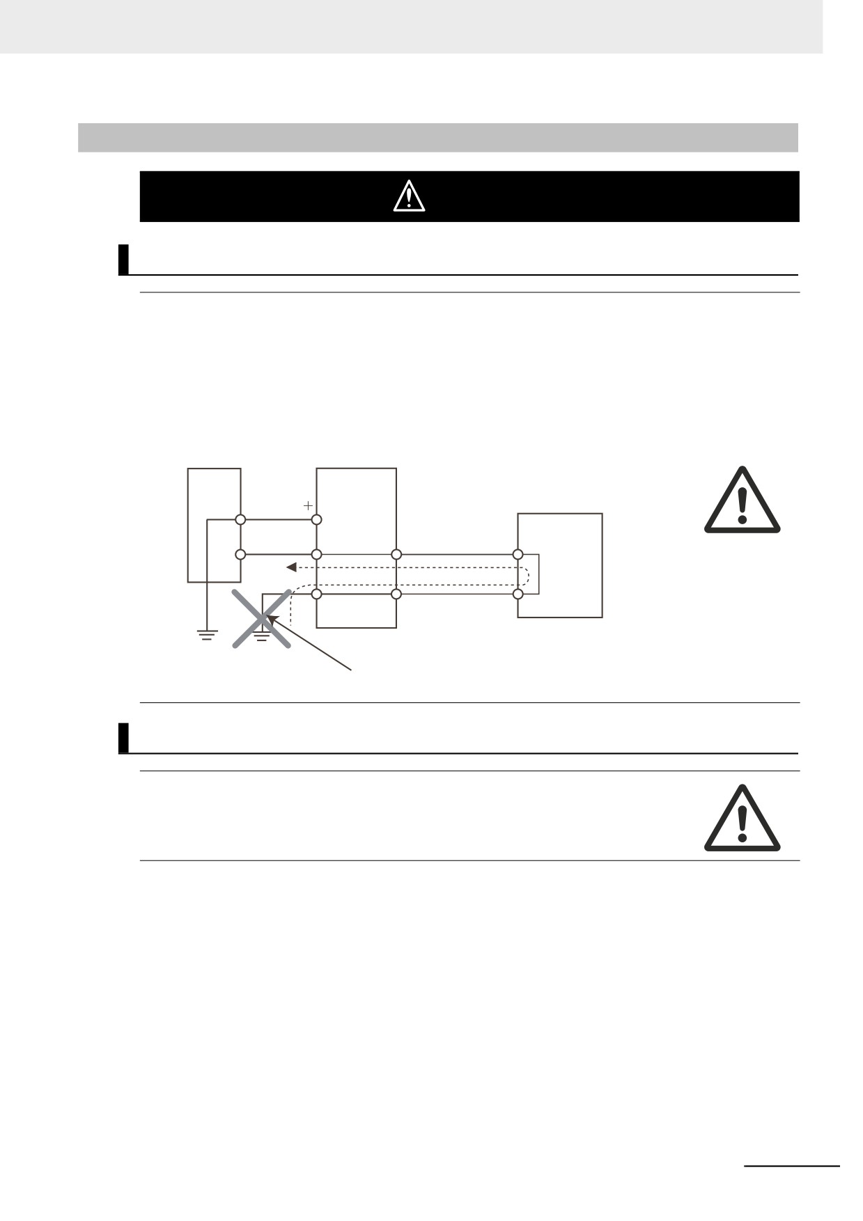
In the case of the NB Series, when grounding the positive terminal of power supply of 24 V to
the NB, do not ground functional grounding terminal at NB side. Some functions of a PC
connected to the NB may cause a short circuit and the NB Unit may cause damage.
• Caution:
Depending on the types of PC, SG terminals of RS-232C port or USB port and contour of connector can
be connected. As the contour of tool port of the NB and the functional grounding terminal are not insu-
lated, they are connected. Therefore, connecting the PC allows GND terminal and functional grounding
terminal of the NB to be connected. If the power supply of 24V to the NB is grounded positively, ground-
ing the functional grounding terminal allows a short circuit as shown in the diagram below and may result
in damage.
Power
NB
Supply
24V
PC
0V GND
SG
Cable
SG
Functional
Grounding
Contour Contour
Grounding Grounding
Do not ground the functional grounding.
Test Function
The Test Function is performed on PC, and it has different behaviors with actual NB running
system. A problem may occur due to communication timing, cable differences and unexpected
PC circumstances (such as freeze). When the Test Function is performed, please consider
possible unexpected circumstances on the actual NB running system and confirm that any
dangerous event will not occur beforehand.
17
Precautions for Safe Use
Precautions for Safe Use
•
When unpacking the NB Units and the peripheral devices, check carefully for any external scratches
or other damages. Also, shake the Units gently and check for any abnormal sound.
•
The NB Unit must be installed in a control panel.
•
The mounting panel must be between 1.6 and 4.8 mm thick. Tighten the Mounting Brackets evenly to a
torque of between 0.5 and 0.6 Nxm to maintain water and dust resistance. If the tightening torque
exceeds the specified value, or the tightening is not even, deformation of the front panel may occur.
What is more, make sure the panel is not dirty or warped and that it is strong enough to hold the Units.
•
Do not let metal particles enter the Units when preparing the panel.
•
Do not connect an AC power supply to the DC power terminals.
•
Use a DC power with a slight voltage fluctuation and reinforced or double insulation, and that will
provide a stable output even if the input is momentarily interrupted for 10 ms.
Rated Power Supply Voltage: DC 24 V (Allowable range DC 20.4 ~ 27.6 V)
•
Do not perform a dielectric voltage test.
•
Before connecting the power supply to the NB unit, mount the cable on the terminal block. Make the
connection by using terminal screws crimping on a twisted-pair cable with a crimping range of 12~26
AWG, and only 6.5 mm of insulation peel of the cable needs to be peeled off. Tighten the terminal
screws at a torque of between 0.3 and 0.5 Nxm. Make sure the screws are properly tightened. Do not
use the terminal block of NB3Q-TW01B for other models. NB3Q-TW01B has different pin definitions
on the terminal block.
•
To prevent malfunctions caused by noise, ground the Unit correctly.
•
Do not touch the packaging part of the circuit board with your bare hands. Discharge any static
electricity from your body before handling the board.
•
When using the No. 6 pin of the serial communication port COM1 connector for a voltage of DC+5V,
make sure the supply equipment’s current capacity is below 250mA before using it. The DC+5V
voltage output of the NB unit is +5V±5%, and the maximum current is 250mA. (The serial
communication port COM1 of NB3Q-TW00B and NB3Q-TW01B is unable to output the current.)
•
Turn OFF the power supply before connecting or disconnecting cables.
•
Always keep the connector screws firmly tightened after the communication cable is connected.
•
Do not pull on the cables or bend the cables beyond their natural limit.
Do not place heavy objects on top of the cables or other wiring lines. Doing so may break the cables.
•
Confirm the safety of the system before turning ON or OFF the power supply, or pressing the reset button.
•
The whole system may stop depending on how the power supply is turned ON or OFF. Turn ON/OFF
the power supply according to the specified procedure.
•
Reset by pressing the reset button, or restart the power supply, once the DIP switch settings are changed.
•
To ensure the system’s safety, make sure to incorporate a program that can confirm the normal
functionality of the NB Unit before running the system.
•
Start actual system application only after sufficiently checking screen data, macros and the operation
of the program at the host side.
•
Do not press the touch panel with a force greater than 30 N.
•
Do not use hard or pointed objects to operate or scrub the screen, otherwise the surface of the
screen may be damaged.
•
Confirm the safety of the system before pressing the touch panel.
•
Signals from the touch switches may not be input if the touch switches are pressed consecutively at
high speed. Confirm each input before proceeding to the next one.
•
Do not accidentally press the touch panel when the backlight is not lit or when the display does not
appear. Make sure of the safety of the system before pressing the touch panel.
•
To use numeric input functions safely, always make maximum and minimum limit settings.
•
Before initializing screen data, confirm that existing data is backed up at the NB-Designer.
18
Precautions for Safe Use
• When changing the password with the screen, do not reset or turn OFF the power supply until writing
is finished. Failure to save the password may cause the screen to fail to function.
• When using an equipment monitor, confirm the safety of the system before carrying out the following operations:
• Changing monitor data.
• Changing operation mode.
• Forced set/reset.
• Changing the current value or the set value.
• Do not connect a USB connector to any device that is not applicable.
• When connecting the equipment with the USB HOST connector, make sure the supply equipment’s
current capacity is below 150mA before using it. The DC+5V voltage output of the NB Unit is
+5V±5%, and the maximum current is 150mA.
• Before connecting a USB connector to a device, make sure that the device is free of damage.
• Commercially available and the recommended USB HUBs are different from the general
specifications of the NB Unit. The unit may not function well in an environment subject to noise, static
electricity. Therefore, when using a USB HUB, employ sufficient noise and static electricity insulation
measures, or install it at a site free of noise or static electricity.
• While uploading or downloading screen data or system programs, do not perform the following
operations that may corrupt the screen data or the system program:
• Turning OFF the power supply of the NB Unit.
• Pressing the PT’s reset switch.
• Dispose of the Units and batteries according to local ordinances as they apply.
•
Do not dispose the product into a fire. Doing so may cause the damage with the battery or electronic components.
•
Do not apply an impact with the lithium cell, charge it, dispose it into a fire, or heat it. Doing either of
them may cause an ignition or a bursting.
•
When exporting products with lithium primary batteries containing perchlorate at 6ppb or above to or
delivering them through California, USA, the following precautionary measures have to be publicized.
Perchlorate material - applicable through special processing. Refer to
NB-Series products contain lithium primary batteries. When exporting products containing this kind of
batteries to or delivering them through California, USA, label all the product packages as well as the
appropriate delivery packages.
•
Do not use benzene, paint thinner, or other volatile solvents, and do not use chemically treated cloths.
•
Do not dispose the Units together with general waste at waste yards. When disposing them, follow
the related local ordinances or rules.
•
Cannot replace the backlight lamp inside the NB Unit.
•
Deterioration over time can cause the touch points to move. Calibrate the touch panel periodically.
•
Water resistance will be lost if the front sheet is torn or is peeling off. Do not use the Unit, if the front
sheet is torn or is peeling off.
•
The rubber packing will deteriorate, shrink, or harden depending on the operating environment.
Inspect the rubber packing periodically.
•
The communication cables of the COM1 and COM2 connectors are not interchangeable. Confirm the pins
of the ports before carrying out communications. (NB3Q-TW00B and NB3Q-TW01B only has COM1.)
•
Periodically check the installation conditions in applications where the PT is subject to contact with oil or water.
•
Do not perform the following operations during the communication of the USB memory:
• Turning off the power supply of the NB Unit.
• Pressing the Reset button on the NB Unit.
• Removing the USB memory.
•
Do not use the USB memory in the environment subject to strong vibration.
19
Precautions for Correct Use
Precautions for Correct Use
• Do not install the unit in any of the following locations:
Locations subject to severe changes in temperature
Locations subject to temperatures or humidity outside the range specified in the specifications
Locations subject to condensation as the result of high humidity
Locations subject to corrosive or flammable gases
Locations subject to strong shock or vibration
Locations outdoors subject to direct wind and rain
Locations subject to strong ultraviolet light
Locations subject to dust
Locations subject to direct sunlight
Locations subject to splashing oil or chemicals
• Take appropriate and sufficient countermeasures when installing systems in the following locations:
Locations subject to static electricity or other forms of noise
Locations subject to strong electric field or magnetic field
Locations close to power supply lines
Locations subject to possible exposure to radioactivity
• Precautions for software:
The update, restoration, uninstall and reinstallation of software in running status is prohibited in order
to guarantee the correct use of the product.
20

Conformance to EC Directives
Conformance to EC Directives
NB-Series Programmable Terminals are EMC compliant.
Concepts
OMRON products are electronic devices that are incorporated in machines and manufacturing
installations. OMRON PTs conform to the related EMC Directives (see note) so that the devices and
machines into which they are built can more easily conform to EMC Directives. The actual products
have been through inspections and are completely in accordance with EMC directives. However, when
they are built into customers’ systems, whether the systems also comply with these Directives is up to
the customers for further inspection.
EMC-related performance of OMRON PTs will vary depending on the configuration, wiring, and other
conditions of the OMRON equipment or control panel. The customer must, therefore, perform final
checks to confirm that the overall machine or device conforms to EMC standards.
Note The applicable EMC (Electromagnetic Compatibility) standards are as follows:
EMS (Electromagnetic sensitivity): EN61131-2: 2007
EMI (Electromagnetic Interference): EN61131-2: 2007
Conformance to EC Directives
NB-Series Programmable Terminals are EC compliant. Heed the following precautions in order to
ensure that the customer’s overall machine and device conform to EC Directives.
1 The PT must be installed in a control panel.
2 You must use reinforced insulation or double insulation for the DC power supply and the DC
power supply must have minimal voltage fluctuations and provide a stable output even if the
power supply input is interrupted for 10 ms.
3 The PTs conform to the standard EN 61131-2, but radiated emission characteristics (10m
regulations) may vary depending on the configuration of the control panel used, other devices
connected to the control panel, wiring, and other conditions. You must therefore confirm that the
overall machine or equipment complies with EC Directives.
4 This is a Class A product (Product for industry purpose). It may cause radio interference in
residential areas, in which case the user may be required to take adequate measures to reduce
interference.
Conformance to KC Standards
Observe the following precaution if you use NB-series Programmable Terminals in Korea.
Class A Device (Broadcasting Communications Device for Office Use)
This device obtained EMC registration for office use (Class A), and it is intended to be used in
places other than homes.
Sellers and/or users need to take note of this.
21

Related Manuals
Related Manuals
The related manuals are as follows:
Devices and Software
Manual Name
Manual No.
NB series
NB Series NB-Designer Operation Manual (This manual)
V106
NB Series Setup Manual
V107
NB Series Host Connection Manual
V108
NB Series Startup Guide
V109
PLC
SYSMAC CP Series CP1L CPU Unit Operation Manual
W462
SYSMAC CP Series CP1H/L CPU Unit Programming Manual
W451
SYSMAC CP Series CP1H CPU Unit Operation Manual
W450
SYSMAC CP Series CP1E CPU Unit Hardware USER’S Manual
W479
SYSMAC CP Series CP1E CPU Unit Software USER’S Manual
W480
SYSMAC CP Series CP1E/CP2E CPU UNIT INSTRUCTIONS
W483
REFERENCE MANUAL
SYSMAC CP Series CP1L-EL/EM CPU Unit Operation Manual
W516
SYSMAC CP Series CP2E CPU Unit Hardware USER’S MANUAL
W613
SYSMAC CP Series CP2E CPU Unit Software USER’S MANUAL
W614
SYSMAC C200HX/HG/HE(-E/-ZE) Installation Guide
W302
SYSMAC C200HX/HG/HE Operation Manual
W303
SYSMAC C200HX/HG/HE(-ZE) Operation Manual
W322
SYSMAC CPM1A Operation Manual
W317
SYSMAC CPM2A Operation Manual
W352
SYSMAC CPM1/CPM1A/CPM2A/CPM2C/SRM1(-V2)
W353
Programming Manual
SYSMAC CPM2C Operation Manual
W356
SYSMAC CS1 Series CS1G/H Operation Manual
W339
SYSMAC CS/CJ Series Serial Communications Boards and Serial
W336
Communications Units Operation Manual
SYSMAC CJ Series CJ1G/H(-H) CJ1M CJ1G Operation Manual
W393
SYSMAC CS/CJ Series Programming Manual
W394
SYSMAC CS/CJ Series INSTRUCTIONS Reference Manual
W340
SYSMAC CS/CJ Series Programming Consoles Operation Manual
W341
SYSMAC CS/CJ Series Communications Commands Reference Manual
W342
SYSMAC CJ Series CJ2 CPU Unit Hardware USER’S Manual
W472
SYSMAC CJ Series CJ2 CPU Unit Software USER’S Manual
W473
SYSMAC CS/CJ Series CS1W/CJ1W-ETN21 (100Base-TX)
W420
Ethernet Units Operation Manual Construction of Networks
SYSMAC CS/CJ Series CS1W/CJ1W-ETN21 (100Base-TX)
W421
Ethernet Units Operation Manual Construction of Applications
SYSMAC CS/CJ Series CS1W/CJ1W-EIP21 (100Base-TX)
W465
EtherNet/IPTM Units Operation Manual
NJ Series CPU Unit Hardware USER’S Manual
W500
NJ/NX Series CPU Unit Software USER’S Manual
W501
NJ/NX Series CPU Unit Built-in EtherNet/IPTM Port USER’S Manual
W506
NJ/NX Series Troubleshooting Manual
W503
NX-Series NX102 CPU Unit Hardware User’s Manual
W593
NX-Series NX1P2 CPU Unit Hardware User’s Manual
W578
NX-Series NX1P2 CPU Unit Built-in I/O and Option Board User’s Manual
W579
Safety Controller
G9SP Series Safety Controller OPERATION MANUAL
Z922
External Tool
CX-Programmer Ver.9. Operation Manual
W446
Sysmac Studio Version 1 Operation Manual
W504
22
1
Introduction
This section provides an outline of the NB-Series PTs, including their functions,
features, connection types and communication methods.
1-1
Functions and Structure of NB-Series PTs
1-2
1-1-1
How NB-Series PTs Work at FA Production Sites
1-2
1-1-2
Operations of NB-Series PTs
1-2
1-2
Communicating with the Host
1-4
1-2-1
What’s the Host Link?
1-4
1-2-2
Connecting Methods
1-5
1-2-3
Communicating with the PLC Manufactured by Other Companies
1-6
1-3
System Configuration
1-7
1-3-1
Connectable Peripheral Devices
1-7
1-4
Procedures for NB-Series PTs’ Operation
1-8
1-1
1 Introduction
1-1
Functions and Structure of NB-Series
PTs
The NB-Series Programmable Terminals (PTs) are sophisticated operator interfaces that can indicate
information and perform operations as required at FA production sites. This section provides a brief of
the roles and performances of the NB Series PTs for beginning users.
1-1-1
How NB-Series PTs Work at FA Production Sites
• Monitoring Line Operating Status
The device and operation status of the system can be displayed in real time. Using graphic charts or
other allows display data in easy-to-understand format.
• Instructing FA Staff
PTs can be used to notify system operators if there is a system or device error and to indicate
countermeasures and necessary information.
• Controlling Panel Switches
NB-Series PTs allow the users to create various kinds of switches on the displayed screen. The
values allocated to the switches can be sent to the host by clicking the switches.
1-1-2
Operations of NB-Series PTs
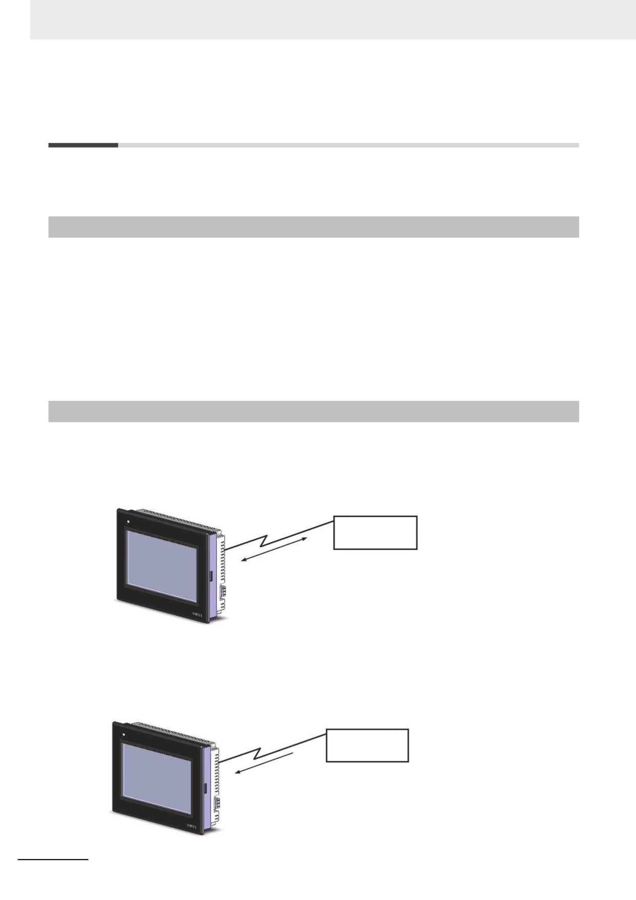
z Transferring Screen Data
The screen data displayed on NB-Series PTs is created by using NB-Designer in the PC. The
screen data is transferred to the NB units through the USB, Ethernet, and the RS-232C or using
USB memory.
Create screen data.
USB, Ethernet, RS-232C
Computer
or USB memory
(NB-Designer)
Screen data
Only when transferring screen data or using the
NB-Designer, the computer can connect with PT.
z Displaying Screens
The data to be displayed on the screens is created by using NB-Designer in PC and the data is
transferred to the PT. The required screen can be displayed by a command from the host or by
operating the touch switches.
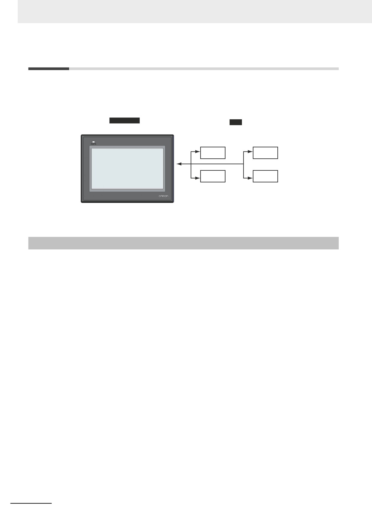
Host
The required screens can be displayed by
using commands from the host or touch
switch operations.
1-2
1 Introduction
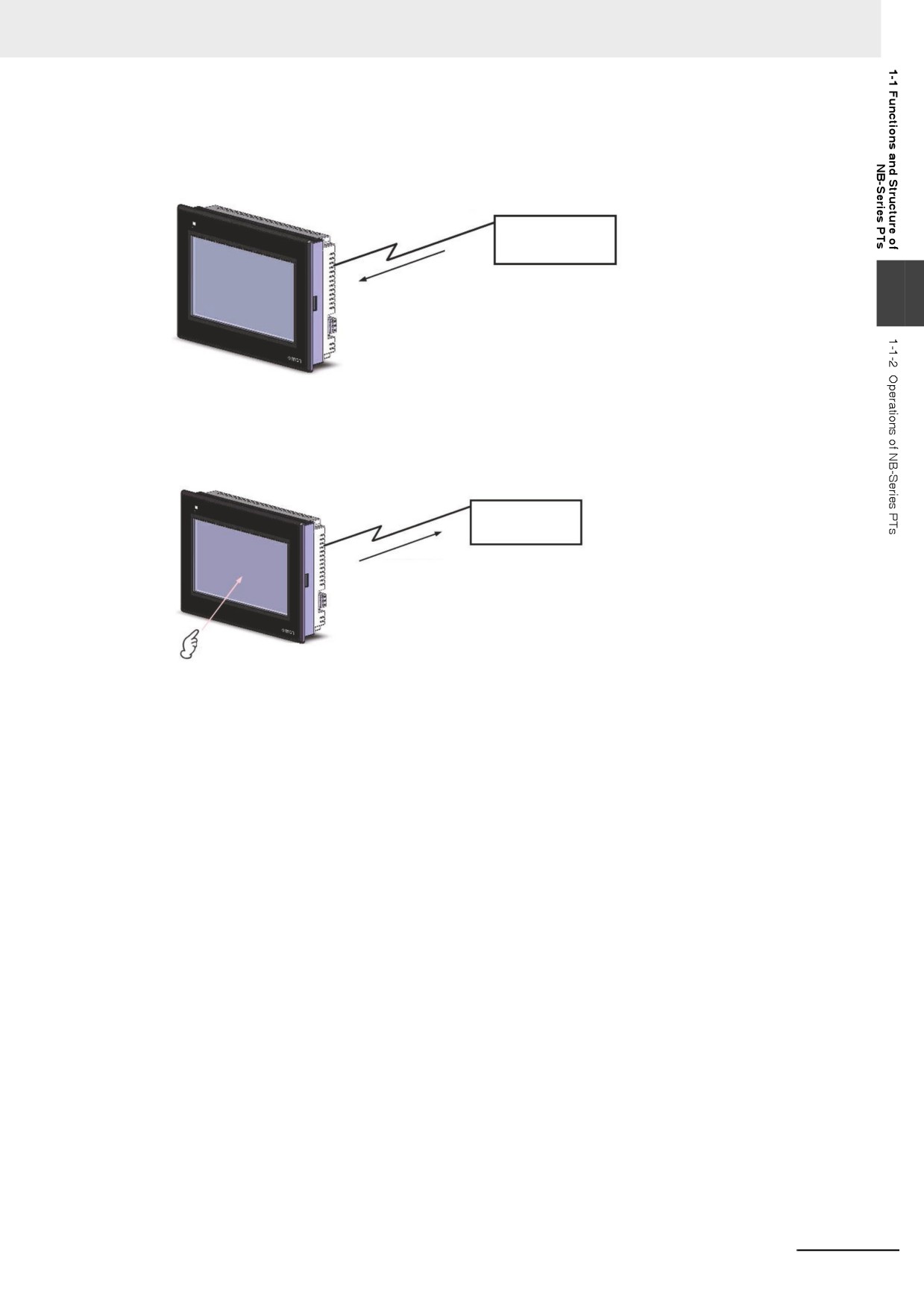
z Reading Data from the Host
NB-Series PTs can be connected to the host by using communication methods such as RS-232C,
RS-485, RS-422A, or Ethernet to automatically read the required data from the host.
RS232, RS485, RS422,
or Ethernet
Host
1
z Sending Data to the Host
The data entered from the touch panel (ON/OFF button status, numeric data and character strings)
can be sent to the host.
Host
ON/OFF status,
numeric data, etc.
Touch panel
1-3
1 Introduction
1-2
Communicating with the Host
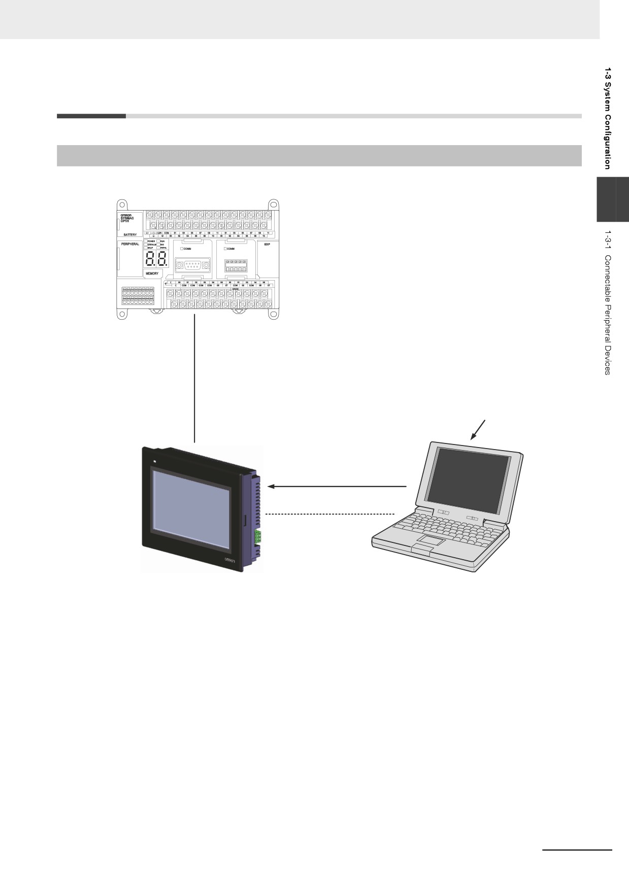
With NB-series PTs, data required for display can be accessed and the words and bits where the
entered data will be stored can be allocated to any area in the PLC. The operations include the direct
reading and writing of the allocated words and bits, the modification of the display status for the
functional objects on the PT screen, and the control and report of the PT status.
NB-Series PT
PLC
DM area
I/O area
Auxiliary area
timers/counters
NB-Series PTs can be connected to the PLC manufactured by OMRON using the Host Link method.
1-2-1
What’s the Host Link?
The Host Link is a kind of optimized and economical communication method for FA system, which is
applicable to link one PT with one PLC or more. The PC can be used to transfer programs to the PLC,
monitor the data area of PLC and control the operation of PLC. The NB-series PTs, however, only
support 1:1 communication. Do not connect multiple PLCs with an NB Unit.
In the system using Host Link system, one PT sends Host Link commands to the PLC and the
commands' processing is completed followed by returning the results of the processing by the PLC (the
host).
System Features:
Connection method: RS-232C or RS-422A
Transmission rate (baud rate): 4800, 9600, 14400, 19200, 38400, 56000, 57600, 115200 and 187500
bps.
The transmission rates of 14400, 56000 and 187500 bps are not supported by the PLC manufactured
by OMRON.
Host monitoring: The PC can be used to transfer or read the PLC programs, and perform reading and
writing of the data area of PLC.
Error check system: Both parity and frame check are performed to estimate the errors occurring during
all the communications.
1-4
1 Introduction
1-2-2
Connecting Methods
RS-232C
RS-232C is a kind of serial physical interface standard formulated by Electric Industry Association
(EIA).
1
RS-232C method is based on 1:1 communication, which is applied to the point-to-point communication
within 15-meter distance due to the existence of common-ground noise and the unavoidable common-
mode interference etc.
RS-485
RS-485 uses the differential signal negative logic and the common 2-wire method, and the connectable
node on the same bus is up to 32. The master-slave communication method, i.e. one master
communicating with multiple slaves, is generally used in the RS-485 communication network.
RS-485 and RS-422A methods can realize 1:N communication, i.e. one host communicating with
multiple PLCs or PTs. The maximum number of PLCs or PTs that can be connected to the host is up to
32, and the maximum transmission distance is 500 meters.
RS-485 is half-duplex communication method that cannot allow the transmission and receiving to be
performed simultaneously.
RS-422A
It is unnecessary to control the data direction due to 4-wire RS-422A interface using separate
transmission and receiving channels. Any necessary signal exchange among the equipments can be
performed by using software method (XON/XOFF Handshaking) or hardware method (control wires).
RS-422A standard with its full name “Electrical Characteristics of Balanced Voltage Digital Interface
Circuits” specifies the characteristics of the interface circuit. Actually, there is also a signal ground, total
5 wires.
Ethernet
Ethernet is a kind of baseband LAN specification, established by Xerox company and jointly developed
by Xerox, Intel and DEC companies, which is the most common communication protocol standard
adopted by the existing LANs. PT uses the standard UTP as the transmission media for the Ethernet.
The NB Series use UTP cables.
The network communications between PT and PLC can be realized through the Ethernet connection.
Connecting the PT and the PLC manufactured by OMRON through the Ethernet allows the data read
and written. What’s more, connecting the PT with PC via the Ethernet can also perform the project
upload/download and the system processing.
1-5
1 Introduction
1-2-3
Communicating with the PLC Manufactured by Other Companies
Besides the connection with the PLC manufactured by OMRON, NB-Series PTs can also communicate
with the devices manufactured by SIEMENS, Mitsubishi Electric Corporation, Schneider Electric, Ltd.,
Delta, Panasonic, Allen-Bradley, GE Fanuc Automation Inc., LG and the PLCs supporting Modbus
protocol. For the manufacturers and the models of the PLCs that can be communicated with, refer to
[NB Series Host Connection Manual].
1-6
1 Introduction
1-3
System Configuration
1-3-1
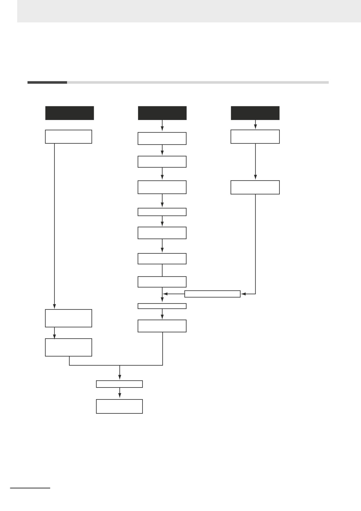
Connectable Peripheral Devices
1
Host
RS-232C cable (15m max.)
RS-485/RS422 cable (500m max.)
Ethernet *2
With NB-Designer Software installed
RS-232C cable
USB cable *1
Ethernet *2
USB memory
PC
NB Unit
Running Windows
*1
When using USB to connect NB Unit with the computer, please refer to 2-3-2 Connecting by USB in NB Series
Setup Manual.
*2
When connecting NB
-TW01B and the Host through the Ethernet, the Host should support the Ethernet
communications.
1-7
1 Introduction
1-4
Procedures for NB-Series PTs’
Operation
Perform the following procedures to operate the NB-Series PTs.
Host
PT
NB-Designer
Installation on the
Host setting
Panel installation
computer
See
2-1-2 Installation onto the Operation panel
in the NB Series Setup Manual
See Section2 Installation and
Startup of NB-Designer
Peripheral connections
• Host link
See
2-4 Communication Connections
in the
NB Series Setup Manual
• Connect to other company's PLC
See NB Series Host Connection Manual
Power connections
Screen creation *5
See2-1-3 Connecting the Power Supply
in the NB Series Setup Manual
See Section3 Functions of
Power ON *1
NB-Designer
Kernel and Rootfs
installation *2
See Section4 Functions of NB Manager
Transferring to system
setting mode *3
SeeSection3 System Setting Mode
in the NB Series Setup Manual
Tranferring to user
project mode
Screen transfer
See
3-15 Download
Host connections
PT connections
Settings/com check
Programming
Operation
System
maintenance *4
*1
The system will enter RUN mode after the screen data is input.
*2
System program is installed only under special circumstances, such as when the system program is
transformed or repaired.
*3
The system setting mode can be entered by using the DIP SW on the back side.
*4
When the abnormalities occur during the operation, the operations such as checking input/output and
confirming the setting state etc can be performed as required.
*5
Use only alphanumerics in a file name of a project file or graphic library and folder where those files are stored.
It may cause a compile error when edited in countries except the file’s origin country.
1-8
///////////////////////////////////////