Cisco Industrial Ethernet 4000, 4010 and 5000 Switch Software. Configuration Guide (2022) - page 27
Configuring IP Multicast Routing
Prerequisites
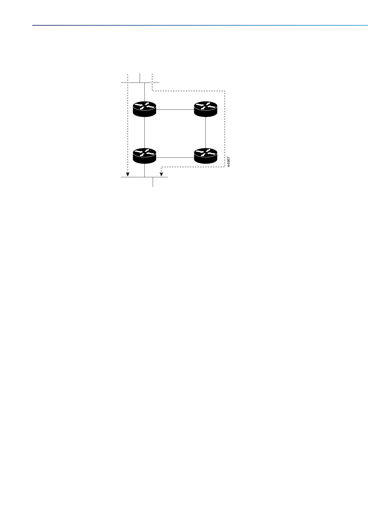
Figure 91
Shared Tree and Source Tree (Shortest-Path Tree)
Source
Router A
Router B
Source tree
Shared tree
(shortest
from RP
path tree)
Router C
RP
Receiver
If the data rate warrants, leaf routers (routers without any downstream connections) on the shared tree can use the data
distribution tree rooted at the source. This type of distribution tree is called a shortest-path tree or source tree. By default,
the software switches to a source tree upon receiving the first data packet from a source.
This process describes the move from a shared tree to a source tree:
1. A receiver joins a group; leaf Router C sends a join message toward the RP.
2. The RP puts a link to Router C in its outgoing interface list.
3. A source sends data; Router A encapsulates the data in a register message and sends it to the RP.
4. The RP forwards the data down the shared tree to Router C and sends a join message toward the source. At this
point, data might arrive twice at Router C, once encapsulated and once natively.
5. When data arrives natively (unencapsulated) at the RP, it sends a register-stop message to Router A.
6. By default, reception of the first data packet prompts Router C to send a join message toward the source.
7. When Router C receives data on (S,G), it sends a prune message for the source up the shared tree.
8. The RP deletes the link to Router C from the outgoing interface of (S,G). The RP triggers a prune message toward
the source.
Join and prune messages are sent for sources and RPs. They are sent hop-by-hop and are processed by each PIM
device along the path to the source or RP. Register and register-stop messages are not sent hop-by-hop. They are sent
by the designated router that is directly connected to a source and are received by the RP for the group.
Multiple sources sending to groups use the shared tree.
You can configure the PIM device to stay on the shared tree. For more information, see Delaying the Use of PIM
Shortest-Path Tree, page 752.
Prerequisites
To use multicast routing, the switch must be running the IP services image.
727
Configuring IP Multicast Routing
Guidelines and Limitations
Be familiar with the information in the Information About Cisco’s Implementation of IP Multicast Routing, page 717
and Guidelines and Limitations, page 728.
Guidelines and Limitations
PIMv1 and PIMv2 Interoperability
The Cisco PIMv2 implementation provides interoperability and transition between Version 1 and Version 2, although there
might be some minor problems.
You can upgrade to PIMv2 incrementally. PIM Versions 1 and 2 can be configured on different routers and multilayer
switches within one network. Internally, all routers and multilayer switches on a shared media network must run the same
PIM version. Therefore, if a PIMv2 device detects a PIMv1 device, the Version 2 device downgrades itself to Version 1
until all Version 1 devices have been shut down or upgraded.
PIMv2 uses the BSR to discover and announce RP-set information for each group prefix to all the routers and multilayer
switches in a PIM domain. PIMv1, together with the Auto-RP feature, can perform the same tasks as the PIMv2 BSR.
However, Auto-RP is a standalone protocol, separate from PIMv1, and is a proprietary Cisco protocol. PIMv2 is a
standards track protocol in the IETF. We recommend that you use PIMv2. The BSR mechanism interoperates with
Auto-RP on Cisco routers and multilayer switches. For more information, see Auto-RP and BSR Configuration Guidelines,
page 728.
When PIMv2 devices interoperate with PIMv1 devices, Auto-RP should have already been deployed. A PIMv2 BSR that
is also an Auto-RP mapping agent automatically advertises the RP elected by Auto-RP. That is, Auto-RP sets its single
RP on every router or multilayer switch in the group. Not all routers and switches in the domain use the PIMv2 hash
function to select multiple RPs.
Dense-mode groups in a mixed PIMv1 and PIMv2 region need no special configuration; they automatically interoperate.
Sparse-mode groups in a mixed PIMv1 and PIMv2 region are possible because the Auto-RP feature in PIMv1
interoperates with the PIMv2 RP feature. Although all PIMv2 devices can also use PIMv1, we recommend that the RPs
be upgraded to PIMv2. To ease the transition to PIMv2, we have these recommendations:
Use Auto-RP throughout the region.
Configure sparse-dense mode throughout the region.
If Auto-RP is not already configured in the PIMv1 regions, configure Auto-RP. For more information, see Configuring
Auto-RP, page 741.
Auto-RP and BSR Configuration Guidelines
There are two approaches to using PIMv2. You can use Version 2 exclusively in your network or migrate to Version 2 by
employing a mixed PIM version environment.
If your network is all Cisco routers and multilayer switches, you can use either Auto-RP or BSR.
If you have non-Cisco routers in your network, you must use BSR.
If you have Cisco PIMv1 and PIMv2 routers and multilayer switches and non-Cisco routers, you must use both
Auto-RP and BSR. If your network includes routers from other vendors, configure the Auto-RP mapping agent and
the BSR on a Cisco PIMv2 device. Ensure that no PIMv1 device is located in the path a between the BSR and a
non-Cisco PIMv2 device.
Because bootstrap messages are sent hop-by-hop, a PIMv1 device prevents these messages from reaching all
routers and multilayer switches in your network. Therefore, if your network has a PIMv1 device in it and only Cisco
routers and multilayer switches, it is best to use Auto-RP.
If you have a network that includes non-Cisco routers, configure the Auto-RP mapping agent and the BSR on a Cisco
PIMv2 router or multilayer switch. Ensure that no PIMv1 device is on the path between the BSR and a non-Cisco
PIMv2 router.
728
Configuring IP Multicast Routing
Guidelines and Limitations
If you have non-Cisco PIMv2 routers that need to interoperate with Cisco PIMv1 routers and multilayer switches, both
Auto-RP and a BSR are required. We recommend that a Cisco PIMv2 device be both the Auto-RP mapping agent
and the BSR. For more information, see Using Auto-RP and a BSR, page 751.
PIM Stub Routing Configuration Guidelines
Guidelines and limitations for PIM stub routing are as follows:
Before configuring PIM stub routing, you must have IP multicast routing configured on both the stub router and the
central router. You must also have PIM mode (dense-mode, sparse-mode, or dense-sparse-mode) configured on
the uplink interface of the stub router.
The PIM stub router does not route the transit traffic between the distribution routers. Unicast (EIGRP) stub routing
enforces this behavior. You must configure unicast stub routing to assist the PIM stub router behavior.
Only directly connected multicast (IGMP) receivers and sources are allowed in the Layer 2 access domains. The PIM
protocol is not supported in access domains.
The redundant PIM stub router topology is not supported.
Restrictions for Legacy Applications Within the SSM Range
Existing applications in a network predating Source-Specific Multicast (SSM) do not work within the SSM range unless
they are modified to support (S, G) channel subscriptions. Therefore, enabling SSM in a network can cause problems for
existing applications if they use addresses within the designated SSM range.
Address Management Restrictions
Address management is still necessary to some degree when SSM is used with Layer 2 switching mechanisms. Cisco
Group Management Protocol (CGMP), IGMP snooping, or Router-Port Group Management Protocol (RGMP) support only
group-specific filtering, not (S, G) channel-specific filtering. If different receivers in a switched network request different
(S, G) channels sharing the same group, they do not benefit from these existing mechanisms. Instead, both receivers
receive all (S, G) channel traffic and filter out the unwanted traffic on input. Because SSM can re-use the group addresses
in the SSM range for many independent applications, this situation can lead to decreased traffic filtering in a switched
network. For this reason, it is important to use random IP addresses from the SSM range for an application to minimize
the chance for re-use of a single address within the SSM range between different applications. For example, an
application service providing a set of television channels should, even with SSM, use a different group for each television
(S, G) channel. This setup guarantees that multiple receivers to different channels within the same application service
never experience traffic aliasing in networks that include Layer 2 switches.
IGMP Snooping and CGMP Limitations
IGMPv3 uses new membership report messages that might not be correctly recognized by older IGMP snooping
switches.
For more information about switching issues related to IGMP (especially with CGMP), refer to the “Configuring IGMP
Version 3” section of the “Configuring IP Multicast Routing” chapter.
State Maintenance Limitations
In PIM-SSM, the last hop router continues to periodically send (S, G) join messages if appropriate (S, G) subscriptions
are on the interfaces. Therefore, as long as receivers send (S, G) subscriptions, the shortest path tree (SPT) state from
the receivers to the source is maintained, even if the source does not send traffic for longer periods of time (or even
never).
This case is opposite to PIM-SM, where (S, G) state is maintained only if the source is sending traffic and receivers are
joining the group. If a source stops sending traffic for more than 3 minutes in PIM-SM, the (S, G) state is deleted and only
re-established after packets from the source arrive again through the RPT. Because no mechanism in PIM-SSM notifies
a receiver that a source is active, the network must maintain the (S, G) state in PIM-SSM as long as receivers are
requesting receipt of that channel.
729

Configuring IP Multicast Routing
Default Settings
SSM Mapping Configuration Guidelines
Guidelines and limitations for SSM mapping:
The SSM mapping feature does not have all the benefits of full SSM. Because SSM mapping takes a group join from
a host and identifies this group with an application associated with one or more sources, it can only support one
such application per group. Full SSM applications can still share the same group as in SSM mapping.
Enable IGMPv3 with care on the last hop router when you rely solely on SSM mapping as a transition solution for full
SSM. When you enable both SSM mapping and IGMPv3 and the hosts already support IGMPv3 (but not SSM), the
hosts send IGMPv3 group reports. SSM mapping does not support these IGMPv3 group reports, and the router does
not correctly associate sources with these reports.
Default Settings
Feature
Default Setting
Multicast routing
Disabled on all interfaces.
PIM version
Version 2.
PIM mode
No mode is defined.
PIM RP address
None configured.
PIM domain border
Disabled.
PIM multicast boundary
None.
Candidate BSRs
Disabled.
Candidate RPs
Disabled.
Shortest-path tree threshold rate
0 kbps.
PIM router query message interval
30 seconds.
Configuring IP Multicast Routing
This section includes the following topics:
Configuring Basic Multicast Routing, page 731 (required)
Configuring PIM Stub Routing, page 733 (optional)
Configuring Source-Specific Multicast, page 734
Configuring SSM Mapping, page 735
Configuring a Rendezvous Point, page 739 (required if the interface is in sparse-dense mode, and you want to treat
the group as a sparse group)
Using Auto-RP and a BSR, page 751 (required for non-Cisco PIMv2 devices to interoperate with Cisco PIM v1
devices))
Monitoring the RP Mapping Information, page 751 (optional)
Troubleshooting PIMv1 and PIMv2 Interoperability Problems, page 752 (optional)
730
Configuring IP Multicast Routing
Configuring IP Multicast Routing
Configuring Basic Multicast Routing
You must enable IP multicast routing and configure the PIM version and the PIM mode. Then the software can forward
multicast packets, and the switch can populate its multicast routing table.
Note: To enable IP multicast routing, the switch must be running the IP services image.
You can configure an interface to be in PIM dense mode, sparse mode, or sparse-dense mode. The switch populates its
multicast routing table and forwards multicast packets it receives from its directly connected LANs according to the mode
setting. You must enable PIM in one of these modes for an interface to perform IP multicast routing. Enabling PIM on an
interface also enables IGMP operation on that interface.
Note: If you enable PIM on multiple interfaces and most of these interfaces are not part of the outgoing interface list,
when IGMP snooping is disabled the outgoing interface might not be able to sustain line rate for multicast traffic because
of the extra, unnecessary replication.
In populating the multicast routing table, dense-mode interfaces are always added to the table. Sparse-mode interfaces
are added to the table only when periodic join messages are received from downstream devices or when there is a
directly connected member on the interface. When forwarding from a LAN, sparse-mode operation occurs if there is an
RP known for the group. If so, the packets are encapsulated and sent toward the RP. When no RP is known, the packet
is flooded in a dense-mode fashion. If the multicast traffic from a specific source is sufficient, the receiver’s first-hop
router might send join messages toward the source to build a source-based distribution tree.
By default, multicast routing is disabled, and there is no default mode setting. Follow this procedure to enable IP
multicasting, to configure a PIM version, and to configure a PIM mode. This procedure is required.
BEFORE YOU BEGIN
Decide which PIM mode to use.
Ensure that the interface on which you are enabling multicast routing has an IP address assigned to it.
731

Configuring IP Multicast Routing
Configuring IP Multicast Routing
DETAILED STEPS
Command
Purpose
1.
configure terminal
Enter global configuration mode.
2.
ip multicast-routing distributed
Enable IP multicast distributed switching.
3.
interface interface-id
Specify the Layer 3 interface on which you want to enable
multicast routing, and enter interface configuration mode.
The specified interface must be one of the following:
A routed port: a physical port that has been configured as a
Layer 3 port by entering the no switchport interface
configuration command.
An SVI: a VLAN interface created by using the interface
vlan vlan-id global configuration command.
4.
no shutdown
Enable the port, if necessary. By default, user network interfaces
(UNIs) and enhanced network interfaces (ENIs) are disabled,
and network node interfaces (NNIs) are enabled.
5.
ip pim version [1 | 2]
Configure the PIM version on the interface.
By default, Version 2 is enabled and is the recommended
setting.
An interface in PIMv2 mode automatically downgrades to PIMv1
mode if that interface has a PIMv1 neighbor. The interface
returns to Version 2 mode after all Version 1 neighbors are shut
down or upgraded.
For more information, see PIMv1 and PIMv2 Interoperability,
page 728.
6.
ip pim {dense-mode |
Enable a PIM mode on the interface.
sparse-mode |
sparse-dense-mode}
By default, no mode is configured.
The keywords have these meanings:
dense-mode—Enables dense mode of operation.
sparse-mode—Enables sparse mode of operation. If you
configure sparse-mode, you must also configure an RP. For
more information, see Configuring a Rendezvous Point,
page 739.
sparse-dense-mode—Causes the interface to be treated in
the mode in which the group belongs. Sparse-dense-mode
is the recommended setting.
7.
end
Return to privileged EXEC mode.
8.
show running-config
Verify your entries.
9.
copy running-config
(Optional) Save your entries in the configuration file.
startup-config
To disable multicasting, use the no ip multicast-routing distributed global configuration command. To return to the
default PIM version, use the no ip pim version interface configuration command. To disable PIM on an interface, use the
no ip pim interface configuration command.
732

Configuring IP Multicast Routing
Configuring IP Multicast Routing
EXAMPLE
This example enables IP multicast distributed switching and specifies the PIM mode:
Switch# configure terminal
Switch(config)# ip multicast-routing distributed
Switch(config)# interface Gigabitethernet 1/0/0
Switch(config-if)# ip pim sparse-dense-mode
Switch(config-if)# end
Configuring PIM Stub Routing
The PIM Stub routing feature supports multicast routing between the distribution layer and the access layer. It supports
two types of PIM interfaces, uplink PIM interfaces, and PIM passive interfaces. A routed interface configured with the PIM
passive mode does not pass or forward PIM control traffic, it only passes and forwards IGMP traffic.
This procedure is optional.
BEFORE YOU BEGIN
You must have IP multicast routing configured on both the stub router and the central router.
You must have PIM mode (dense-mode, sparse-mode, or dense-sparse-mode) configured on the uplink interface
of the stub router.
You must configure EIGRP stub routing to assist the PIM stub router behavior.
DETAILED STEPS
Command
Purpose
1.
configure terminal
Enter global configuration mode.
2.
interface interface-id
Specify the interface on which you want to enable PIM stub
routing, and enter interface configuration mode.
3.
ip pim passive
Configure the PIM stub feature on the interface.
4.
end
Return to privileged EXEC mode.
5.
show ip pim interface
Display the PIM stub that is enabled on each interface.
6.
show running-config
Verify your entries.
7.
copy running-config
(Optional) Save your entries in the configuration file.
startup-config
To disable PIM stub routing on an interface, use the no ip pim passive interface configuration command.
EXAMPLE
In this example, IP multicast routing is enabled, Switch A PIM uplink port 25 is configured as a routed uplink port with
spare-dense-mode enabled. PIM stub routing is enabled on the VLAN 100 interfaces and on Gigabit Ethernet port 20
in Figure 88 on page 721:
Switch(config)# ip multicast-routing distributed
Switch(config)# interface GigabitEthernet0/25
Switch(config-if)# no switchport
Switch(config-if)# ip address 3.1.1.2 255.255.255.0
Switch(config-if)# ip pim sparse-dense-mode
Switch(config-if)# exit
Switch(config)# interface vlan100
733

Configuring IP Multicast Routing
Configuring IP Multicast Routing
Switch(config-if)# ip pim passive
Switch(config-if)# exit
Switch(config)# interface GigabitEthernet0/20
Switch(config-if)# ip pim passive
Switch(config-if)# exit
Switch(config)# interface vlan100
Switch(config-if)# ip address 100.1.1.1 255.255.255.0
Switch(config-if)# ip pim passive
Switch(config-if)# exit
Switch(config)# interface GigabitEthernet0/20
Switch(config-if)# no switchport
Switch(config-if)# ip address 10.1.1.1 255.255.255.0
Switch(config-if)# ip pim passive
Switch(config-if)# end
To verify that PIM stub is enabled for each interface, use the show ip pim interface privileged EXEC command:
Switch# show ip pim interface
Address Interface Ver/ Nbr Query DR DR
Mode Count Intvl Prior
3.1.1.2 GigabitEthernet0/25 v2/SD 1 30 1 3.1.1.2
100.1.1.1 Vlan100 v2/P 0 30 1 100.1.1.1
10.1.1.1 GigabitEthernet0/20 v2/P 0 30 1 10.1.1.1
Use these privileged EXEC commands to display information about PIM stub configuration and status:
show ip pim interface displays the PIM stub that is enabled on each interface.
show ip igmp detail displays the interested clients that have joined the specific multicast source group.
show ip igmp mroute verifies that the multicast stream forwards from the source to the interested clients.
Configuring Source-Specific Multicast
This section describes how to configure source-specific multicast (SSM).
BEFORE YOU BEGIN
See Information About Source-Specific Multicast, page 723 and Guidelines and Limitations, page 728.
DETAILED STEPS
Command
Purpose
1.
ip pim ssm [default | range access-list]
Define the SSM range of IP multicast addresses.
2.
interface type number
Select an interface that is connected to hosts on which
IGMPv3 can be enabled, and enter the interface
configuration mode.
3.
ip pim {sparse-mode |
Enable PIM on an interface. You must use either sparse
sparse-dense-mode}
mode or sparse-dense mode.
4.
ip igmp version 3
Enable IGMPv3 on this interface. The default version of
IGMP is set to Version 2.
EXAMPLE
The following example shows how to configure a device (running IGMPv3) for SSM:
ip multicast-routing
ip pim ssm default
!
734
Configuring IP Multicast Routing
Configuring IP Multicast Routing
interface GigabitEthernet3/1/0
ip address 172.21.200.203 255.255.255.0
description backbone interface
ip pim sparse-mode
!
interface GigabitEthernet3/2/0
ip address 131.108.1.2 255.255.255.0
ip pim sparse-mode
description ethernet connected to hosts
ip igmp version 3
!
Verifying SSM Configuration
Command
Purpose
show ip igmp groups detail
Display the (S, G) channel subscription through IGMPv3.
show ip mroute
Display whether a multicast group supports SSM service or whether a
source-specific host report was received.
Configuring SSM Mapping
This section includes the following topics:
Configuring Static SSM Mapping, page 735 (required)
Configuring DNS-Based SSM Mapping, page 736 (required)
Configuring Static Traffic Forwarding with SSM Mapping, page 738 (optional)
Configuring Static SSM Mapping
BEFORE YOU BEGIN
See Information About Source Specific Multicast Mapping, page 725 and SSM Mapping Configuration Guidelines,
page 730.
Before you configure SSM mapping, enable IP multicast routing, enable PIM sparse mode, and configure SSM. For
information on enabling IP multicast routing and PIM sparse mode, see Configuring Basic Multicast Routing,
page 731.
Before you configure static SSM mapping, you must configure access control lists (ACLs) that define the group
ranges to be mapped to source addresses.
735

Configuring IP Multicast Routing
Configuring IP Multicast Routing
DETAILED STEPS
Command
Purpose
1.
configure terminal
Enter global configuration mode.
2.
ip igmp ssm-map enable
Enable SSM mapping for groups in the configured SSM range.
Note: By default, this command enables DNS-based SSM
mapping.
3.
no ip igmp ssm-map query dns
(Optional) Disable DNS-based SSM mapping.
Note: Disable DNS-based SSM mapping if you only want to rely
on static SSM mapping. By default, the ip igmp ssm-map
global configuration command enables DNS-based SSM
mapping.
4.
ip igmp ssm-map static access-list
Configure static SSM mapping.
source-address
The ACL supplied for access-list defines the groups to be
mapped to the source IP address entered for the
source-address.
Note: You can configure additional static SSM mappings. If
additional SSM mappings are configured and the router
receives an IGMPv1 or IGMPv2 membership report for a group
in the SSM range, the switch determines the source addresses
associated with the group by using each configured ip igmp
ssm-map static command. The switch associates up to 20
sources per group.
5.
Repeat Step 4 to configure
—
additional static SSM mappings, if
required.
6.
end
Return to privileged EXEC mode.
7.
show running-config
Verify your entries.
8.
copy running-config
(Optional) Save your entries in the configuration file.
startup-config
EXAMPLE
The following example shows how to enable static SSM mapping. In this example, the router is configured to statically
map groups that match ACL 11 to source address 172.16.8.11 and to statically map groups that match ACL 10 to source
address 172.16.8.10.
Switch(config)# ip igmp ssm-map enable
Switch(config)# ip igmp ssm-map static 11 172.16.8.11
Switch(config)# ip igmp ssm-map static 10 172.16.8.10
Switch(config)# end
Configuring DNS-Based SSM Mapping
To configure DNS-based SSM mapping, you need to create a DNS server zone or add records to an existing zone. If the
routers that are using DNS-based SSM mapping are also using DNS for other purposes, you should use a normally
configured DNS server. If DNS-based SSM mapping is the only DNS implementation being used on the router, you can
configure a false DNS setup with an empty root zone or a root zone that points back to itself.
736

Configuring IP Multicast Routing
Configuring IP Multicast Routing
BEFORE YOU BEGIN
See Information About Source Specific Multicast Mapping, page 725 and SSM Mapping Configuration Guidelines,
page 730.
Before you configure SSM mapping, enable IP multicast routing, enable PIM sparse mode, and configure SSM. For
information on enabling IP multicast routing and PIM sparse mode, see Configuring Basic Multicast Routing,
page 731.
Before you can configure and use SSM mapping with DNS lookups, you must be able to add records to a running
DNS server. If you do not already have a DNS server running, you need to install one.
You can use a product such as Cisco Network Registrar. Go to this URL for more information:
DETAILED STEPS
Command
Purpose
1.
configure terminal
Enter global configuration mode.
2.
ip igmp ssm-map enable
Enable SSM mapping for groups in a configured SSM range.
3.
ip igmp ssm-map query dns
(Optional) Enable DNS-based SSM mapping.
By default, the ip igmp ssm-map command enables
DNS-based SSM mapping. Only the no form of this command
is saved to the running configuration.
Note: Use this command to re-enable DNS-based SSM
mapping if DNS-based SSM mapping is disabled.
4.
ip domain multicast domain-prefix
(Optional) Change the domain prefix used by the switch for
DNS-based SSM mapping.
By default, the switch uses the ip-addr.arpa domain prefix.
5.
ip name-server server-address1
Specify the address of one or more name servers to use for
[server-address2...
name and address resolution.
server-address6]
6.
Repeat Step 5 to configure
—
additional DNS servers for
redundancy, if required.
7.
end
Return to privileged EXEC mode.
8.
show running-config
Verify your entries.
9.
copy running-config
(Optional) Save your entries in the configuration file.
startup-config
EXAMPLE
The following example shows how to configure DNS-based SSM mapping:
Switch(config)# ip igmp ssm-map enable
Switch(config)# ip name-server 10.0.0.0
Switch(config)# end
737

Configuring IP Multicast Routing
Configuring IP Multicast Routing
Configuring Static Traffic Forwarding with SSM Mapping
Use static traffic forwarding with SSM mapping to statically forward SSM traffic for certain groups. When static traffic
forwarding with SSM mapping is configured, the last hop router uses Domain Name System (DNS)-based SSM mapping
to determine the sources associated with a group. The resulting (S, G) channels are then statically forwarded.
BEFORE YOU BEGIN
Configure DNS-based SSM mapping as described in the Configuring DNS-Based SSM Mapping, page 736.
DETAILED STEPS
Command
Purpose
1.
configure terminal
Enter global configuration mode.
2.
interface type number
Select an interface on which to statically forward traffic for a
multicast group using SSM mapping, and enter interface
configuration mode.
Note: Static forwarding of traffic with SSM mapping works with
either DNS-based SSM mapping or statically configured SSM
mapping.
3.
ip igmp static-group
Configure SSM mapping to statically forward a (S, G) channel
group-address source ssm-map
from the interface.
Use this command if you want to statically forward SSM traffic
for certain groups. Use DNS-based SSM mapping to determine
the source addresses of the channels.
4.
show running-config
Verify your entries.
5.
copy running-config
(Optional) Save your entries in the configuration file.
startup-config
EXAMPLE
The following example shows how to configure group address 239.1.2.1 to use SSM mapping for statically forwarded
groups on Ethernet interface 0:
interface ethernet 0
ip igmp static-group 239.1.2.1 source ssm-map
738

Configuring IP Multicast Routing
Configuring IP Multicast Routing
Verifying SSM Mapping Configuration
Command
Purpose
show ip igmp ssm-mapping
Display information about SSM mapping.
show ip igmp ssm-mapping
Display the sources that SSM mapping uses for a particular
group-address
group.
show ip igmp groups [group-name |
Display the multicast groups with receivers that are directly
group-address | interface-type
connected to the router and that were learned through IGMP.
interface-number] [detail]
show host
Display the default domain name, the style of name lookup
service, a list of name server hosts, and the cached list of
hostnames and addresses.
debug ip igmp group-address
Display the IGMP packets received and sent and IGMP
host-related events.
Configuring a Rendezvous Point
You must have an RP if the interface is in sparse-dense mode and if you want to treat the group as a sparse group. You
can use several methods, as described in these sections:
Manually Assigning an RP to Multicast Groups, page 739
Configuring Auto-RP, page 741 (a standalone, Cisco-proprietary protocol separate from PIMv1)
Configuring PIMv2 BSR, page 746 (a standards track protocol in the Internet Engineering Task Force (IETF)
You can use Auto-RP, BSR, or a combination of both, depending on the PIM version you are running and the types of
routers in your network. For more information, see PIMv1 and PIMv2 Interoperability, page 728 and the Auto-RP and BSR
Configuration Guidelines, page 728.
Manually Assigning an RP to Multicast Groups
This section explains how to manually configure an RP. If the RP for a group is learned through a dynamic mechanism
(such as Auto-RP or BSR), you need not perform this task for that RP.
Senders of multicast traffic announce their existence through register messages received from the source’s first-hop
router (designated router) and forwarded to the RP. Receivers of multicast packets use RPs to join a multicast group by
using explicit join messages. RPs are not members of the multicast group; rather, they serve as a meeting place for
multicast sources and group members.
You can configure a single RP for multiple groups defined by an access list. If there is no RP configured for a group, the
multilayer switch treats the group as dense and uses the dense-mode PIM techniques. This procedure is optional.
BEFORE YOU BEGIN
Review the Information About PIM, page 719 and Guidelines and Limitations, page 728.
739

Configuring IP Multicast Routing
Configuring IP Multicast Routing
DETAILED STEPS
Command
Purpose
1.
configure terminal
Enter global configuration mode.
2.
ip pim rp-address ip-address
Configure the address of a PIM RP.
[access-list-number] [override]
By default, no PIM RP address is configured. You must configure
the IP address of RPs on all routers and multilayer switches
(including the RP). If there is no RP configured for a group, the
switch treats the group as dense, using the dense-mode PIM
techniques.
A PIM device can be an RP for more than one group. Only one
RP address can be used at a time within a PIM domain. The
access-list conditions specify for which groups the device is an
RP.
For ip-address, enter the unicast address of the RP in
dotted-decimal notation.
(Optional) For access-list-number, enter an IP standard
access list number from 1 to 99. If no access list is
configured, the RP is used for all groups.
(Optional) The override keyword means that if there is a
conflict between the RP configured with this command and
one learned by Auto-RP or BSR, the RP configured with this
command prevails.
3.
access-list access-list-number
Create a standard access list, repeating the command as many
{deny | permit} source
times as necessary.
[source-wildcard]
For access-list-number, enter the access list number
specified in Step 2.
The deny keyword denies access if the conditions are
matched. The permit keyword permits access if the
conditions are matched.
For source, enter the multicast group address for which the
RP should be used.
(Optional) For source-wildcard, enter the wildcard bits in
dotted decimal notation to be applied to the source. Place
ones in the bit positions that you want to ignore.
Recall that the access list is always terminated by an implicit
deny statement for everything.
4.
end
Return to privileged EXEC mode.
5.
show running-config
Verify your entries.
6.
copy running-config
(Optional) Save your entries in the configuration file.
startup-config
To remove an RP address, use the no ip pim rp-address ip-address [access-list-number] [override] global
configuration command.
740
Configuring IP Multicast Routing
Configuring IP Multicast Routing
EXAMPLE
This example shows how to configure the address of the RP to 147.106.6.22 for multicast group 225.2.2.2 only:
Switch(config)# access-list 1 permit 225.2.2.2 0.0.0.0
Switch(config)# ip pim rp-address 147.106.6.22 1
Configuring Auto-RP
Auto-RP uses IP multicast to automate the distribution of group-to-RP mappings to all Cisco routers and multilayer
switches in a PIM network. It has these benefits:
It is easy to use multiple RPs within a network to serve different group ranges.
It provides load splitting among different RPs and arrangement of RPs according to the location of group participants.
It avoids inconsistent, manual RP configurations on every router and multilayer switch in a PIM network, which can
cause connectivity problems.
Note: If you configure PIM in sparse mode or sparse-dense mode and do not configure Auto-RP, you must manually
configure an RP as described in the Manually Assigning an RP to Multicast Groups, page 739.
Note: If routed interfaces are configured in sparse mode, Auto-RP can still be used if all devices are configured with a
manual RP address for the Auto-RP groups.
These sections describe how to configure Auto-RP:
Setting up Auto-RP in a New Internetwork, page 741 (optional)
Adding Auto-RP to an Existing Sparse-Mode Cloud, page 741 (optional)
Preventing Join Messages to False RPs, page 743 (optional)
Filtering Incoming RP Announcement Messages, page 743 (optional)
Setting up Auto-RP in a New Internetwork
If you are setting up Auto-RP in a new internetwork, you do not need a default RP because you configure all the interfaces
for sparse-dense mode. Follow the process described in the Adding Auto-RP to an Existing Sparse-Mode Cloud,
page 741. However, omit Step 3 if you want to configure a PIM router as the RP for the local group.
Adding Auto-RP to an Existing Sparse-Mode Cloud
This section contains some suggestions for the initial deployment of Auto-RP into an existing sparse-mode cloud to
minimize disruption of the existing multicast infrastructure. This procedure is optional.
BEFORE YOU BEGIN
Review the Auto-RP, page 721 and Guidelines and Limitations, page 728.
Configure a default RP as described in the Manually Assigning an RP to Multicast Groups, page 739.
741
Configuring IP Multicast Routing
Configuring IP Multicast Routing
DETAILED STEPS
Command
Purpose
1.
show running-config
Verify that a default RP is already configured on all PIM devices
and the RP in the sparse-mode network. It was previously
configured with the ip pim rp-address global configuration
command.
This step is not required for spare-dense-mode environments.
The selected RP should have good connectivity and be available
across the network. Use this RP for the global groups (for
example 224.x.x.x and other global groups). Do not reconfigure
the group address range that this RP serves. RPs dynamically
discovered through Auto-RP take precedence over statically
configured RPs. Assume that it is desirable to use a second RP
for the local groups.
2.
configure terminal
Enter global configuration mode.
3.
ip pim send-rp-announce
Configure another PIM device to be the candidate RP for local
interface-id scope ttl group-list
groups.
access-list-number interval
For interface-id, enter the interface type and number that
seconds
identifies the RP address. Valid interfaces include physical
ports, port channels, and VLANs.
For scope ttl, specify the time-to-live value in hops. Enter a
hop count that is high enough so that the RP-announce
messages reach all mapping agents in the network. There
is no default setting. The range is 1 to 255.
For group-list access-list-number, enter an IP standard
access list number from 1 to 99. If no access list is
configured, the RP is used for all groups.
For interval seconds, specify how often the announcement
messages must be sent. The default is 60 seconds. The
range is 1 to 16383.
4.
access-list access-list-number
Create a standard access list, repeating the command as many
{deny | permit} source
times as necessary.
[source-wildcard]
For access-list-number, enter the access list number
specified in Step 3.
The deny keyword denies access if the conditions are
matched. The permit keyword permits access if the
conditions are matched.
For source, enter the multicast group address range for
which the RP should be used.
(Optional) For source-wildcard, enter the wildcard bits in
dotted decimal notation to be applied to the source. Place
ones in the bit positions that you want to ignore.
Recall that the access list is always terminated by an implicit
deny statement for everything.
742

Configuring IP Multicast Routing
Configuring IP Multicast Routing
Command
Purpose
5.
ip pim send-rp-discovery scope
Find a switch whose connectivity is not likely to be interrupted,
ttl
and assign it the role of RP-mapping agent.
For scope ttl, specify the time-to-live value in hops to limit the
RP discovery packets. All devices within the hop count from the
source device receive the Auto-RP discovery messages. These
messages tell other devices which group-to-RP mapping to use
to avoid conflicts (such as overlapping group-to-RP ranges).
There is no default setting. The range is 1 to 255.
6.
end
Return to privileged EXEC mode.
7.
show running-config
Verify your entries.
show ip pim rp mapping
Display active RPs that are cached with associated multicast
routing entries.
show ip pim rp
Display the information cached in the routing table.
8.
copy running-config
(Optional) Save your entries in the configuration file.
startup-config
To remove the PIM device configured as the candidate RP, use the no ip pim send-rp-announce interface-id global
configuration command. To remove the switch as the RP-mapping agent, use the no ip pim send-rp-discovery global
configuration command.
EXAMPLE
This example shows how to send RP announcements out all PIM-enabled interfaces for a maximum of 31 hops. The IP
address of port 1 is the RP. Access list 5 describes the group for which this switch serves as RP:
Switch(config)# ip pim send-rp-announce gigabitethernet0/1 scope 31 group-list 5
Switch(config)# access-list 5 permit 224.0.0.0 15.255.255.255
Preventing Join Messages to False RPs
Find whether the ip pim accept-rp command was previously configured throughout the network by using the show
running-config privileged EXEC command. If the ip pim accept-rp command is not configured on any device, this
problem can be addressed later. In those routers or multilayer switches already configured with the ip pim accept-rp
command, you must enter the command again to accept the newly advertised RP.
To accept all RPs advertised with Auto-RP and reject all other RPs by default, use the ip pim accept-rp auto-rp global
configuration command. This procedure is optional.
If all interfaces are in sparse mode, use a default-configured RP to support the two well-known groups 224.0.1.39 and
224.0.1.40. Auto-RP uses these two well-known groups to collect and distribute RP-mapping information. When this is
the case and the ip pim accept-rp auto-rp command is configured, another ip pim accept-rp command accepting the
RP must be configured as follows:
Switch(config)# ip pim accept-rp 172.10.20.1 1
Switch(config)# access-list 1 permit 224.0.1.39
Switch(config)# access-list 1 permit 224.0.1.40
Filtering Incoming RP Announcement Messages
You can add configuration commands to the mapping agents to prevent a maliciously configured router from
masquerading as a candidate RP and causing problems. This procedure is optional.
743
Configuring IP Multicast Routing
Configuring IP Multicast Routing
BEFORE YOU BEGIN
This command should only be configured on RP mapping agents.
If you use more than one RP-mapping agent, you must configure the same filters on all mapping agents to avoid
inconsistencies in Auto-RP operations.
An improperly configured ip pim rp-announce-filter command may result in RP announcements being ignored. In
addition, the ip pim rp-announce-filter command should only be configured on the mapping agent; if not, the
command will fail because non-mapping agents do not listen to group 224.0.1.39 and do not know how to distribute
the necessary group-to-RP mappings.
744

Configuring IP Multicast Routing
Configuring IP Multicast Routing
DETAILED STEPS
Command
Purpose
1.
configure terminal
Enter global configuration mode.
2.
ip pim rp-announce-filter rp-list
Filter incoming RP announcement messages.
access-list-number group-list
access-list-number
Enter this command on each mapping agent in the network.
Without this command, all incoming RP-announce messages
are accepted by default.
For rp-list access-list-number, configure an access list of
candidate RP addresses that, if permitted, is accepted for the
group ranges supplied in the group-list access-list-number
variable. If this variable is omitted, the filter applies to all
multicast groups.
If more than one mapping agent is used, the filters must be
consistent across all mapping agents to ensure that no
conflicts occur in the Group-to-RP mapping information.
3.
access-list access-list-number
Create a standard access list, repeating the command as
{deny | permit} source
many times as necessary.
[source-wildcard]
For access-list-number, enter the access list number
specified in Step 2.
The deny keyword denies access if the conditions are
matched. The permit keyword permits access if the
conditions are matched.
Create an access list that specifies from which routers and
multilayer switches the mapping agent accepts candidate
RP announcements (rp-list ACL).
Create an access list that specifies the range of multicast
groups from which to accept or deny (group-list ACL).
For source, enter the multicast group address range for
which the RP should be used.
(Optional) For source-wildcard, enter the wildcard bits in
dotted decimal notation to be applied to the source. Place
ones in the bit positions that you want to ignore.
Recall that the access list is always terminated by an implicit
deny statement for everything.
4.
end
Return to privileged EXEC mode.
5.
show running-config
Verify your entries.
6.
copy running-config startup-config
(Optional) Save your entries in the configuration file.
To remove a filter on incoming RP announcement messages, use the no ip pim rp-announce-filter rp-list
access-list-number [group-list access-list-number] global configuration command.
745
Configuring IP Multicast Routing
Configuring IP Multicast Routing
EXAMPLE
This example shows a sample configuration on an Auto-RP mapping agent that is used to prevent candidate RP
announcements from being accepted from unauthorized candidate RPs:
Switch(config)# ip pim rp-announce-filter rp-list 10 group-list 20
Switch(config)# access-list 10 permit host 172.16.5.1
Switch(config)# access-list 10 permit host 172.16.2.1
Switch(config)# access-list 20 deny 239.0.0.0 0.0.255.255
Switch(config)# access-list 20 permit 224.0.0.0 15.255.255.255
In this example, the mapping agent accepts candidate RP announcements from only two devices, 172.16.5.1 and
172.16.2.1. The mapping agent accepts candidate RP announcements from these two devices only for multicast groups
that fall in the group range of 224.0.0.0 to 239.255.255.255. The mapping agent does not accept candidate RP
announcements from any other devices in the network. Furthermore, the mapping agent does not accept candidate RP
announcements from 172.16.5.1 or 172.16.2.1 if the announcements are for any groups in the 239.0.0.0 through
239.255.255.255 range. This range is the administratively scoped address range.
Configuring PIMv2 BSR
These sections describe how to set up BSR in your PIMv2 network:
Defining the PIM Domain Border, page 746 (optional)
Defining the IP Multicast Boundary, page 747 (optional)
Configuring Candidate BSRs, page 748 (optional)
Configuring Candidate RPs, page 749 (optional)
Defining the PIM Domain Border
As IP multicast becomes more widespread, the chance of one PIMv2 domain bordering another PIMv2 domain is
increasing. Because these two domains probably do not share the same set of RPs, BSR, candidate RPs, and candidate
BSRs, you need to constrain PIMv2 BSR messages from flowing into or out of the domain. Allowing these messages to
leak across the domain borders could adversely affect the normal BSR election mechanism and elect a single BSR across
all bordering domains and co-mingle candidate RP advertisements, resulting in the election of RPs in the wrong domain.
This procedure is optional.
BEFORE YOU BEGIN
Review the Bootstrap Router, page 722 and Guidelines and Limitations, page 728.
746
Configuring IP Multicast Routing
Configuring IP Multicast Routing
DETAILED STEPS
Command
Purpose
1.
configure terminal
Enter global configuration mode.
2.
interface interface-id
Specify the interface to be configured, and enter interface
configuration mode.
3.
no shutdown
Enable the port, if necessary. By default, UNIs and ENIs are
disabled, and NNIs are enabled.
4.
ip pim bsr-border
Define a PIM bootstrap message boundary for the PIM domain.
Enter this command on each interface that connects to other
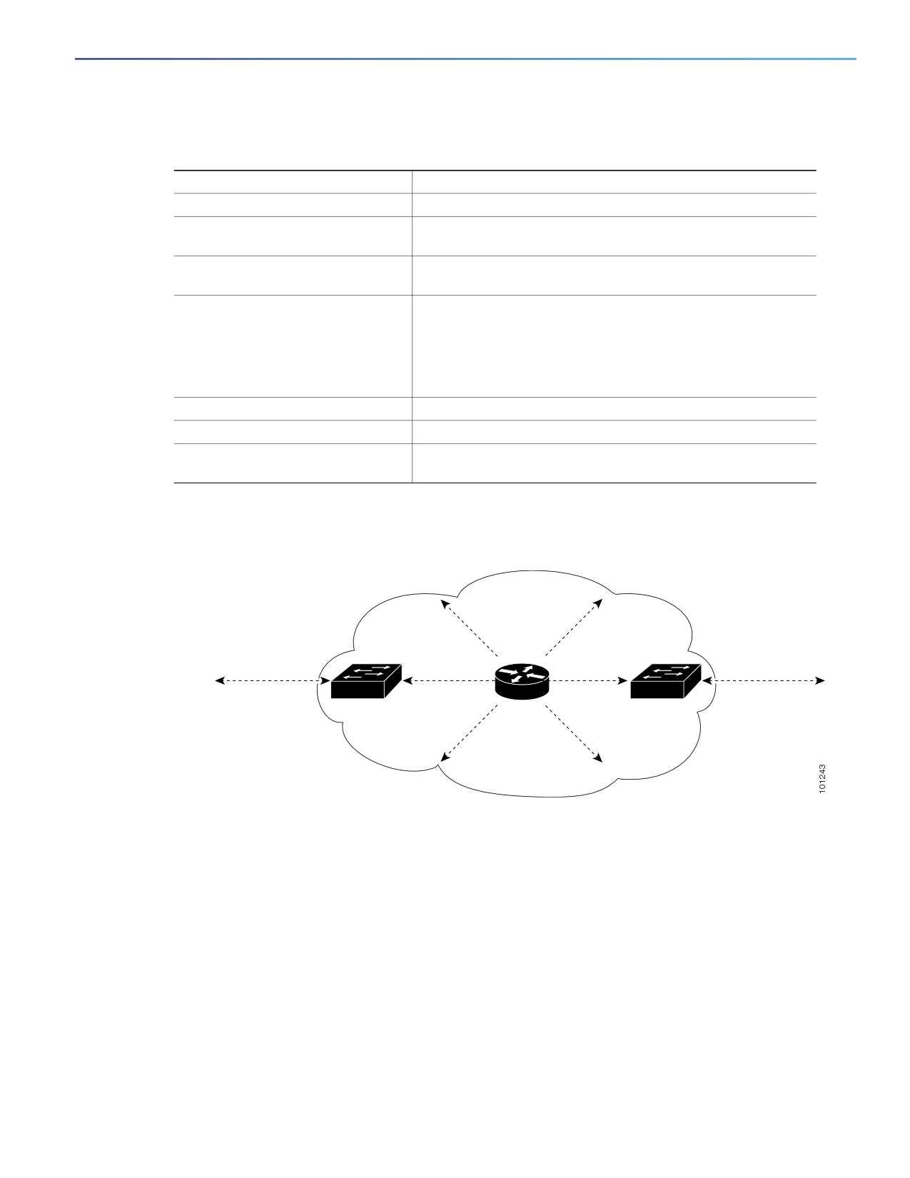
bordering PIM domains. This command instructs the switch to
neither send or receive PIMv2 BSR messages on this interface
as shown in Figure 92 on page 747.
5.
end
Return to privileged EXEC mode.
6.
show running-config
Verify your entries.
7.
copy running-config
(Optional) Save your entries in the configuration file.
startup-config
To remove the PIM border, use the no ip pim bsr-border interface configuration command.
Figure 92
Constraining PIMv2 BSR Messages
PIMv2 sparse-mode
Configure the
network
Configure the
ip pim bsr-border
ip pim bsr-border
command on
BSR
BSR
command on
this interface.
messages
messages
this interface.
Neighboring
Neighboring
Layer 3
Layer 3
PIMv2 domain
BSR
PIMv2 domain
switch
switch
EXAMPLE
The following example configures the interface to be the PIM domain border:
interface ethernet 1
ip pim bsr-border
Defining the IP Multicast Boundary
You define a multicast boundary to prevent Auto-RP messages from entering the PIM domain. You create an access list
to deny packets destined for 224.0.1.39 and 224.0.1.40, which carry Auto-RP information. This procedure is optional.
BEFORE YOU BEGIN
Review the Information About PIM, page 719 and the Guidelines and Limitations, page 728.
747

Configuring IP Multicast Routing
Configuring IP Multicast Routing
DETAILED STEPS
Command
Purpose
1.
configure terminal
Enter global configuration mode.
2.
access-list access-list-number
Create a standard access list, repeating the command as many
deny source [source-wildcard]
times as necessary.
For access-list-number, the range is 1 to 99.
The deny keyword denies access if the conditions are
matched.
For source, enter multicast addresses 224.0.1.39 and
224.0.1.40, which carry Auto-RP information.
(Optional) For source-wildcard, enter the wildcard bits in
dotted decimal notation to be applied to the source. Place
ones in the bit positions that you want to ignore.
Recall that the access list is always terminated by an implicit
deny statement for everything.
3.
interface interface-id
Specify the interface to be configured, and enter interface
configuration mode.
4.
no shutdown
Enable the port, if necessary. By default, UNIs and ENIs are
disabled, and NNIs are enabled.
5.
ip multicast boundary
Configure the boundary, specifying the access list you created
access-list-number
in Step 2.
6.
end
Return to privileged EXEC mode.
7.
show running-config
Verify your entries.
8.
copy running-config
(Optional) Save your entries in the configuration file.
startup-config
To remove the boundary, use the no ip multicast boundary interface configuration command.
EXAMPLE
This example shows a portion of an IP multicast boundary configuration that denies Auto-RP information:
Switch(config)# access-list 1 deny 224.0.1.39
Switch(config)# access-list 1 deny 224.0.1.40
Switch(config)# interface gigabitethernet0/1
Switch(config-if)# ip multicast boundary 1
Configuring Candidate BSRs
You can configure one or more candidate BSRs. The devices serving as candidate BSRs should have good connectivity
to other devices and be in the backbone portion of the network. This procedure is optional.
BEFORE YOU BEGIN
Enable PIM on the interface using the ip pim command as described in the Configuring Basic Multicast Routing,
page 731.
748

Configuring IP Multicast Routing
Configuring IP Multicast Routing
DETAILED STEPS
Command
Purpose
1.
configure terminal
Enter global configuration mode.
2.
ip pim bsr-candidate interface-id
Configure your switch to be a candidate BSR.
hash-mask-length [priority]
For interface-id, enter the interface on this switch from
which the BSR address is derived to make it a candidate.
This interface must be enabled with PIM. Valid interfaces
include physical ports, port channels, and VLANs.
For hash-mask-length, specify the mask length (32 bits
maximum) that is to be ANDed with the group address
before the hash function is called. All groups with the same
seed hash correspond to the same RP. For example, if this
value is 24, only the first 24 bits of the group addresses
matter.
(Optional) For priority, enter a number from 0 to 255. The
BSR with the larger priority is preferred. If the priority
values are the same, the device with the highest IP address
is selected as the BSR. The default is 0.
3.
end
Return to privileged EXEC mode.
4.
show running-config
Verify your entries.
5.
copy running-config
(Optional) Save your entries in the configuration file.
startup-config
To remove this device as a candidate BSR, use the no ip pim bsr-candidate global configuration command.
EXAMPLE
This example shows how to configure a candidate BSR, which uses the IP address 172.21.24.18 on a port as the
advertised BSR address, uses 30 bits as the hash-mask-length, and has a priority of 10:
Switch(config)# interface gigabitethernet0/2
Switch(config-if)# ip address 172.21.24.18 255.255.255.0
Switch(config-if)# ip pim sparse-dense-mode
Switch(config-if)# ip pim bsr-candidate gigabitethernet0/2 30 10
Configuring Candidate RPs
You can configure one or more candidate RPs. Similar to BSRs, the RPs should also have good connectivity to other
devices and be in the backbone portion of the network. An RP can serve the entire IP multicast address space or a portion
of it. Candidate RPs send candidate RP advertisements to the BSR. When deciding which devices should be RPs,
consider these options:
In a network of Cisco routers and multilayer switches where only Auto-RP is used, any device can be configured as
an RP.
In a network that includes only Cisco PIMv2 routers and multilayer switches and with routers from other vendors, any
device can be used as an RP.
In a network of Cisco PIMv1 routers, Cisco PIMv2 routers, and routers from other vendors, configure only Cisco
PIMv2 routers and multilayer switches as RPs.
This procedure is optional.
749

Configuring IP Multicast Routing
Configuring IP Multicast Routing
BEFORE YOU BEGIN
Enable PIM on the interface using the ip pim command as described in the Configuring Basic Multicast Routing,
page 731.
DETAILED STEPS
Command
Purpose
1.
configure terminal
Enter global configuration mode.
2.
ip pim rp-candidate interface-id
Configure your switch to be a candidate RP.
[group-list access-list-number]
For interface-id, specify the interface whose associated IP
address is advertised as a candidate RP address. Valid
interfaces include physical ports, port channels, and
VLANs.
(Optional) For group-list access-list-number, enter an IP
standard access list number from 1 to 99. If no group-list
is specified, the switch is a candidate RP for all groups.
3.
access-list access-list-number
Create a standard access list, repeating the command as many
{deny | permit} source
times as necessary.
[source-wildcard]
For access-list-number, enter the access list number
specified in Step 2.
The deny keyword denies access if the conditions are
matched. The permit keyword permits access if the
conditions are matched.
For source, enter the number of the network or host from
which the packet is being sent.
(Optional) For source-wildcard, enter the wildcard bits in
dotted decimal notation to be applied to the source. Place
ones in the bit positions that you want to ignore.
Recall that the access list is always terminated by an implicit
deny statement for everything.
4.
end
Return to privileged EXEC mode.
5.
show running-config
Verify your entries.
6.
copy running-config
(Optional) Save your entries in the configuration file.
startup-config
To remove this device as a candidate RP, use the no ip pim rp-candidate interface-id global configuration command.
EXAMPLE
This example shows how to configure the switch to advertise itself as a candidate RP to the BSR in its PIM domain.
Standard access list number 4 specifies the group prefix associated with the RP that has the address identified by a port.
That RP is responsible for the groups with the prefix 239.
Switch(config)# ip pim rp-candidate gigabitethernet0/2 group-list 4
Switch(config)# access-list 4 permit 239.0.0.0 0.255.255.255
750

Configuring IP Multicast Routing
Configuring IP Multicast Routing
Using Auto-RP and a BSR
If there are only Cisco devices in you network (no routers from other vendors), there is no need to configure a BSR.
Configure Auto-RP in a network that is running both PIMv1 and PIMv2.
If you have non-Cisco PIMv2 routers that need to interoperate with Cisco PIMv1 routers and multilayer switches, both
Auto-RP and a BSR are required. We recommend that a Cisco PIMv2 router or multilayer switch be both the Auto-RP
mapping agent and the BSR.
If you must have one or more BSRs, we have these recommendations:
Configure the candidate BSRs as the RP-mapping agents for Auto-RP. For more information, see Configuring
Auto-RP, page 741 and Configuring Candidate BSRs, page 748.
For group prefixes advertised through Auto-RP, the PIMv2 BSR mechanism should not advertise a subrange of these
group prefixes served by a different set of RPs. In a mixed PIMv1 and PIMv2 domain, have backup RPs serve the
same group prefixes. This prevents the PIMv2 DRs from selecting a different RP from those PIMv1 DRs, due to the
longest match lookup in the RP-mapping database.
Follow this procedure to verify the consistency of group-to-RP mappings. This procedure is optional.
BEFORE YOU BEGIN
Review the Auto-RP and BSR Configuration Guidelines, page 728.
DETAILED STEPS
Command
Purpose
1.
show ip pim rp [[group-name
On any Cisco device, display the available RP mappings.
| group-address] | mapping]
(Optional) For group-name, specify the name of the group about
which to display RPs.
(Optional) For group-address, specify the address of the group
about which to display RPs.
(Optional) Use the mapping keyword to display all group-to-RP
mappings of which the Cisco device is aware (either configured
or learned from Auto-RP).
2.
show ip pim rp-hash group
On a PIMv2 router or multilayer switch, confirm that the same RP is the
one that a PIMv1 system chooses.
For group, enter the group address for which to display RP
information.
Monitoring the RP Mapping Information
To monitor the RP mapping information, use these commands in privileged EXEC mode:
show ip pim bsr displays information about the elected BSR.
show ip pim rp-hash group displays the RP that was selected for the specified group.
show ip pim rp [group-name | group-address | mapping] displays how the switch learns of the RP (through the BSR
or the Auto-RP mechanism).
751
Configuring IP Multicast Routing
Configuring Advanced PIM Features
Troubleshooting PIMv1 and PIMv2 Interoperability Problems
When debugging interoperability problems between PIMv1 and PIMv2, check these in the order shown:
1. Verify RP mapping with the show ip pim rp-hash privileged EXEC command, making sure that all systems agree on
the same RP for the same group.
2. Verify interoperability between different versions of DRs and RPs. Make sure the RPs are interacting with the DRs
properly (by responding with register-stops and forwarding decapsulated data packets from registers).
Configuring Advanced PIM Features
This section includes the following topics:
Delaying the Use of PIM Shortest-Path Tree, page 752 (optional)
Modifying the PIM Router-Query Message Interval, page 754 (optional)
Delaying the Use of PIM Shortest-Path Tree
The change from shared to source tree happens when the first data packet arrives at the last-hop router (Router C in
Figure 91 on page 727 in the Information About PIM Shared Tree and Source Tree, page 726). This change occurs
because the ip pim spt-threshold global configuration command controls that timing.
The shortest-path tree requires more memory than the shared tree but reduces delay. You might want to postpone its
use. Instead of allowing the leaf router to immediately move to the shortest-path tree, you can specify that the traffic
must first reach a threshold.
You can configure when a PIM leaf router should join the shortest-path tree for a specified group. If a source sends at a
rate greater than or equal to the specified kbps rate, the multilayer switch triggers a PIM join message toward the source
to construct a source tree (shortest-path tree). If the traffic rate from the source drops below the threshold value, the
leaf router switches back to the shared tree and sends a prune message toward the source.
You can specify to which groups the shortest-path tree threshold applies by using a group list (a standard access list). If
a value of 0 is specified or if the group list is not used, the threshold applies to all groups.
This procedure is optional.
BEFORE YOU BEGIN
Review the Information About PIM Shared Tree and Source Tree, page 726.
752

Configuring IP Multicast Routing
Configuring Advanced PIM Features
DETAILED STEPS
Command
Purpose
1.
configure terminal
Enter global configuration mode.
2.
access-list access-list-number {deny
Create a standard access list.
| permit} source [source-wildcard]
For access-list-number, the range is 1 to 99.
The deny keyword denies access if the conditions are
matched. The permit keyword permits access if the
conditions are matched.
For source, specify the multicast group to which the
threshold will apply.
(Optional) For source-wildcard, enter the wildcard bits
in dotted decimal notation to be applied to the source.
Place ones in the bit positions that you want to ignore.
Recall that the access list is always terminated by an implicit
deny statement for everything.
3.
ip pim spt-threshold {kbps | infinity}
Specify the threshold that must be reached before moving
[group-list access-list-number]
to shortest-path tree (spt).
For kbps, specify the traffic rate in kilobits per second.
The default is 0 kbps.
Note: Because of switch hardware limitations, 0 kbps is the
only valid entry even though the range is 0 to 4294967.
Specify infinity if you want all sources for the specified
group to use the shared tree, never switching to the
source tree.
(Optional) For group-list access-list-number, specify
the access list created in Step 2. If the value is 0 or if the
group-list is not used, the threshold applies to all
groups.
4.
end
Return to privileged EXEC mode.
5.
show running-config
Verify your entries.
6.
copy running-config startup-config
(Optional) Save your entries in the configuration file.
To return to the default setting, use the no ip pim spt-threshold {kbps | infinity} global configuration command.
EXAMPLE
The following example shows how to set a threshold of 4 kbps. If the traffic rate exceeds this threshold, the traffic to a
group from a source causes the router to switch to the shortest path tree to that source.
Switch# configure terminal
Switch(config)# ip pim spt-threshold 4
753

Configuring IP Multicast Routing
Configuring Optional IGMP Features
Modifying the PIM Router-Query Message Interval
PIM routers and multilayer switches send PIM router-query messages to find which device will be the DR for each LAN
segment (subnet). The DR is responsible for sending IGMP host-query messages to all hosts on the directly connected
LAN.
With PIM DM operation, the DR has meaning only if IGMPv1 is in use. IGMPv1 does not have an IGMP querier election
process, so the elected DR functions as the IGMP querier. With PIM SM operation, the DR is the device that is directly
connected to the multicast source. It sends PIM register messages to notify the RP that multicast traffic from a source
needs to be forwarded down the shared tree. In this case, the DR is the device with the highest IP address.
Follow this procedure to modify the router-query message interval. This procedure is optional.
BEFORE YOU BEGIN
Review the Information About PIM, page 719.
DETAILED STEPS
Command
Purpose
1.
configure terminal
Enter global configuration mode.
2.
interface interface-id
Specify the interface to be configured, and enter interface
configuration mode.
3.
no shutdown
Enable the port, if necessary. By default, UNIs and ENIs are
disabled, and NNIs are enabled.
4.
ip pim query-interval seconds
Configure the frequency at which the switch sends PIM
router-query messages.
The default is 30 seconds. The range is 1 to 65535.
5.
end
Return to privileged EXEC mode.
6.
show ip igmp interface
Verify your entries.
[interface-id]
7.
copy running-config
(Optional) Save your entries in the configuration file.
startup-config
To return to the default setting, use the no ip pim query-interval [seconds] interface configuration command.
EXAMPLE
The following example shows how to set the PIM hello interval to 45 seconds:
interface FastEthernet0/1
ip pim query-interval 45
Configuring Optional IGMP Features
This section includes the following topics:
Default IGMP Configuration, page 755
Configuring the Switch as a Member of a Group, page 755 (optional)
Controlling Access to IP Multicast Groups, page 756 (optional)
754

Configuring IP Multicast Routing
Configuring Optional IGMP Features
Changing the IGMP Version, page 757 (optional)
Modifying the IGMP Host-Query Message Interval, page 758 (optional)
Changing the IGMP Query Timeout for IGMPv2, page 760 (optional)
Changing the Maximum Query Response Time for IGMPv2, page 761 (optional)
Configuring the Switch as a Statically Connected Member, page 762 (optional)
Default IGMP Configuration
Feature
Default Setting
Multilayer switch as a member of a multicast group
No group memberships are defined.
Access to multicast groups
All groups are allowed on an interface.
IGMP version
Version 2 on all interfaces.
IGMP host-query message interval
60 seconds on all interfaces.
IGMP query timeout
60 seconds on all interfaces.
IGMP maximum query response time
10 seconds on all interfaces.
Multilayer switch as a statically connected member
Disabled.
Configuring the Switch as a Member of a Group
You can configure the switch as a member of a multicast group and discover multicast reachability in a network. If all the
multicast-capable routers and multilayer switches that you administer are members of a multicast group, pinging that
group causes all these devices to respond. The devices respond to IGMP echo-request packets addressed to a group
of which they are members. Another example is the multicast trace-route tools provided in the software.
This procedure is optional.
BEFORE YOU BEGIN
Caution: Performing this procedure might impact the CPU performance because the CPU will receive all data traffic
for the group address.
755

Configuring IP Multicast Routing
Configuring Optional IGMP Features
DETAILED STEPS
Command
Purpose
1.
configure terminal
Enter global configuration mode.
2.
interface interface-id
Specify the interface to be configured, and enter interface
configuration mode.
3.
no shutdown
Enable the port, if necessary. By default, UNIs and ENIs are
disabled, and NNIs are enabled.
4.
ip igmp join-group
Configure the switch to join a multicast group.
group-address
By default, no group memberships are defined.
For group-address, specify the multicast IP address in dotted
decimal notation.
5.
end
Return to privileged EXEC mode.
6.
show ip igmp interface
Verify your entries.
[interface-id]
7.
copy running-config
(Optional) Save your entries in the configuration file.
startup-config
To cancel membership in a group, use the no ip igmp join-group group-address interface configuration command.
EXAMPLE
This example shows how to enable the switch to join multicast group 255.2.2.2:
Switch(config)# interface gigabitethernet0/1
Switch(config-if)# ip igmp join-group 255.2.2.2
Controlling Access to IP Multicast Groups
The switch sends IGMP host-query messages to find which multicast groups have members on attached local networks.
The switch then forwards to these group members all packets addressed to the multicast group. You can place a filter
on each interface to restrict the multicast groups that hosts on the subnet serviced by the interface can join.
This procedure is optional.
BEFORE YOU BEGIN
Review the Information About IGMP, page 718.
756