Boeing 737 - 600/700/800/900. Operations Manual (1997 year) - page 58
Flight Management, Navigation -
Flight Management System
Operation
Boeing 737 Operations Manual
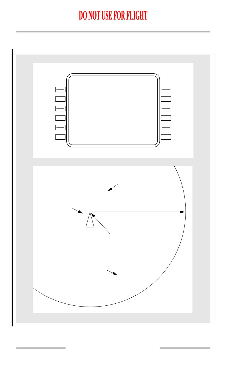
Actual Navigation Performance
[Option - Single FMC with GPS]
PO S SHIFT
3 / 3
G P S
L
G
P S ( L )
G P S - R
<210`/0.1 N M
220`
/0.0N M >
I R S
L
I
R S ( L )
I R S - R
<1 50` /3.9 N M
110`
/2.3N M >
R N P / A C T U A L
R A D I O
12 .0 / 5 . 1
2
N
M
035`
/1.4N M >
- - - - - - - -
-
-
- - - - - - - - - - - - - -
N
A
V STATUS>
<INDE X
Radio Position
035`/1.4NM
GPS(L) Position
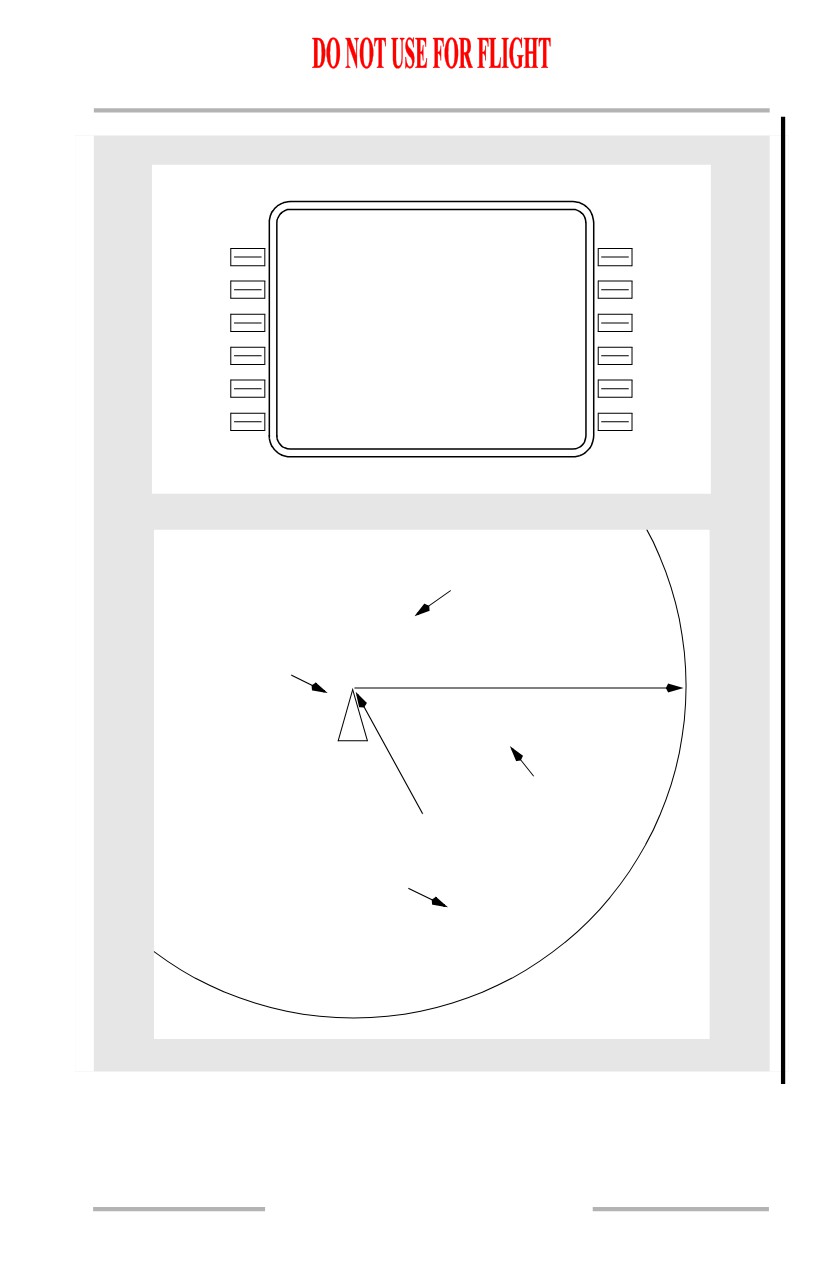
Actual Navigation Performance (ANP)
210`/0.1NM
5.12NM
FMC Combined Position
IRS(L) Position
150`/3.9NM
11.31.8
Flight Management, Navigation -
Flight Management System
Operation
Boeing 737 Operations Manual
[Option - Dual FMC with GPS]
PO S SHIFT
3 / 3
F M
C
L
F M C - R
<2 74` /0.0 N M
094`
/0.3N M >
G P S
L
G
P S ( L )
G P S - R
<210`/0.1 N M
220`
/0.0N M >
I R S
L
I
R S ( 2 )
I R S - R
<1 50` /3.9 N M
110`
/2.3N M >
R N P / A C T U A L
R A D I O
12 .0 / 5 . 1
2
N
M
035`
/1.4N M >
- - - - - - - -
-
-
- - - - - - - - - - - - - -
N
A
V STATUS>
<INDE X
Radio Position
035`/1.4NM
GPS(L) Position
210`/0.1NM
Actual Navigation Performance (ANP)
5.12 NM
IRS(R) Position
110`/2.3NM
FMC Combined Position
IRS(L) Position
150`/3.9NM
11.31.9
Flight Management, Navigation -
Flight Management System
Operation
Boeing 737 Operations Manual
Lateral Navigation (LNAV)
LNAV provides steering commands to the next waypoint. If selected, LNAV
engages when laterally within 3 nautical miles of the active route leg. If outside of
3 nautical miles of the active route leg, LNAV engages if on an intercept heading
of 90 degrees or less and the intercept will occur before the active waypoint. FMC
LNAV guidance normally provides great circle courses between waypoints.
However, when an arrival or approach from the FMC database is entered into the
active route, the FMC can supply commands to fly a constant heading, track, or
follow an arc, as required by the procedure.
Waypoints
Waypoint (navigation fix) identifiers are displayed on the CDU and navigation
display.
The CDU message NOT IN DATA BASE is displayed if a manually entered
waypoint identifier is not stored in the database. The waypoint can still be entered
as a latitude/longitude, place-bearing/distance or place-bearing/place-bearing
waypoint.
FMC-generated waypoints contain a maximum of five characters assigned
according to the following rules.
Navaid Waypoint Names
VHF - waypoints located at VHF navaids (VOR/DME/LOC) are identified by the
official one, two, three or four character facility identifier. Examples:
• Los Angeles VORTAC - LAX
• Tyndall TACAN - PAM
• Riga, Latvia - RIX.
NDB - waypoints located at NDBs are identified by use of the station identifier.
Example:
• Fort Nelson, CAN - YE.
Fix Waypoint Names
Fixes with one-word names - waypoints located at fixes with names containing
five or fewer characters are identified by the name. Examples:
• DOT
• ACRA
• ALPHA.
11.31.10
Flight Management, Navigation -
Flight Management System
Operation
Boeing 737 Operations Manual
Long Waypoint Names
Names with more than five characters are abbreviated using the following rules
sequentially until five characters remain. Double letters are deleted. Examples:
• KIMMEL becomes KIMEL
• COTTON becomes COTON
• RABBITT becomes RABIT.
Keep the first letter, first vowel and last letter. Delete other vowels starting from
right to left. Examples:
• ADOLPH becomes ADLPH
• BAILEY becomes BAILY
• BURWELL becomes BURWL.
Keep the last letter, then delete consonants from right to left. Examples:
• ANDREWS becomes ANDRS
• BRIDGEPORT becomes BRIDT
• HORSBA becomes HORSA.
Fixes with multiword names use the first letter of the first word and abbreviate the
last word, using the above rules sequentially until a total of five characters remain.
Examples:
• CLEAR LAKE becomes CLAKE
• ROUGH ROAD becomes RROAD.
Unnamed Point Waypoint Names
Unnamed turn points, intersections and DME fixes - if an unnamed turn point,
intersection or fix is collocated with a named waypoint or navaid on a different
route structure (such as low altitude routes or an approach), the name or identifier
of the collocated waypoint is used. Example:
• Unnamed turn point on J2 between the Lake Charles (LCH) and New
Orleans (MSY) VORTACs is coincidental with the Lafayette (LFT) low
altitude VORTAC. LFT is used as the identifier for the turn point.
Identifier codes for unnamed turn points not coincidental with named waypoints
are constructed from the identifier of a navaid serving the point and the distance
from the navaid to the point. If the distance is 99 nautical miles or less, the navaid
identifier is placed first, followed by the distance. If the distance is 100 nautical
miles or more, the last two digits are used and placed ahead of the navaid
identifier. Examples (NAVAID - DISTANCE - IDENT):
• INW - 18 - INW18
• CSN - 106 - 06CSN
• TCS - 89 - TCS89.
11.31.11
Flight Management, Navigation -
Flight Management System
Operation
Boeing 737 Operations Manual
Unnamed flight information region (FIR), upper flight information region (UIR),
and controlled airspace reporting points - waypoints located at unnamed FIR,
UIR, and controlled airspace reporting points are identified by the three-letter
airspace type identification followed by a two-digit sequence number.
Unnamed oceanic control area reporting points - positions in the northern
hemisphere use the letters N and E, while positions in the southern hemisphere use
the letters S and W. Latitude always precedes longitude. For longitude, only the
last two digits of the three digit value are used.
Placement of the designator in the five character set indicates whether the first
longitude digit is 0 or 1. The letter is the last character if the longitude is less than
100° and is the third character if the longitude is 100° or greater.
N is used for north latitude, west longitude. E is used for north latitude, east
longitude. S is used for south latitude, east longitude. W is used for south latitude,
west longitude. Examples:
• N50° W040° becomes 5040N
• S52° W075° becomes 5275W
• N75° W170° becomes 75N70
• S07° W120° becomes 07W20
• N50° E020° becomes 5020E
• S50° E020° becomes 5020S
• N06° E110° becomes 06E10
• S06° E110° becomes 06S10.
Procedure Arc Fix Waypoint Names
Unnamed terminal area fixes along a DME arc procedure - unnamed fixes along
a DME arc procedure are identified with the first character D. Characters 2
through 4 indicate the radial on which the fix lies. The last character indicates the
arc radius. The radius is expressed by a letter of the alphabet where A = 1 mile, B
= 2 miles, C = 3 miles, and so forth. Examples:
• EPH252°/24 = D252X
• EPH145°/24 = D145X
• GEG006°/20 = D006T.
An unnamed waypoint along a DME arc with a radius greater than 26 miles is
identified as an unnamed turn point that is not coincidental with a named
waypoint. Examples:
• CPR338°/29 = CPR29
• GEG079°/30 = GEG30.
When there are multiple unnamed waypoints along a DME arc with a radius
greater than 26 miles, the station identifier is reduced to two characters, followed
by the radius, and then a sequence character. Examples:
• CPR134°/29 = CP29A
• CPR190° /29 = CP29B
• CPR201°/29 = CP29C.
11.31.12
Flight Management, Navigation -
Flight Management System
Operation
Boeing 737 Operations Manual
Procedure Fix Waypoint Names
Marker beacons - a marker beacon is identified by the marker type identifier
followed by the runway number. Examples:
• Outer Marker 13R = OM13R
• Middle Marker 21 = MM21.
Runway-related fixes - waypoints located at unnamed runway-related fixes are
identified by adding a two-letter prefix to the runway number. The following list
is used to determine the appropriate prefix:
• RX - runway extension fix
• BM - back course marker
• FA - VFR final approach fix
• MD - minimum descent
• CF - final approach course fix
altitude
• FF - final approach fix
• A - (+ an alpha) step down fix
• IF - initial approach fix
• RW - runway threshold
• OM - outer marker
• MA - missed approach point
other than RW
• MM - middle marker
• TD - touchdown point inboard
• IM - inner marker
of RW.
Examples: OM25L, MM09, IM23, RW04, RW18L.
For airports with more than one approach to the same runway, the two letter prefix
may change to allow different identifiers for the same waypoint. The first letter
identifies the type of fix and the second letter identifies the type approach as
follows:
• C( ) - final approach course fix
•
( )L - localizer only( )B
• F( ) - final approach fix
-backcourse ILS
• P( ) - missed approach point
•
( )D - VOR/DME
• I( ) - initial approach fix
•
( )V - VOR only
• D( ) - minimum descent
•
( )S - VOR with DME points
altitude
•
( )N - NDB
• T( ) - touch down point
•
( )Q - NDB with DME points
• R( ) - runway centerline
•
( )M - MLS
intercept.
•
( )T - Tacan
•
( )I - ILS
•
( )R - RNAV.
Examples: CI32R, PV15, FN24L.
Unnamed turn points - unnamed turn points that are part of a procedure are
identified as a latitude and longitude waypoint. These include waypoints (except
conditional waypoints) defined by flying a course or track from a waypoint
(except conditional waypoints) to a radial or DME distance. These waypoints are
automatically entered in a route by selection of a procedure using these waypoints,
from the departures or arrivals page.
11.31.13
Flight Management, Navigation -
Flight Management System
Operation
Boeing 737 Operations Manual
Airport reference points - airport reference points are identified by the ICAO
identifier.
Duplicate Waypoint Names
Duplicate identifiers - should application of these rules result in more than one
waypoint having the same identifier, then a CDU page change occurs when an
attempt is made to enter the duplicated identifier. The page title is SELECT
DESIRED WPT. The page lists the latitude and longitude of waypoints with the
same identifier and the type of facility or waypoint. Selecting the
latitude/longitude of the desired waypoint enters the correct waypoint on the
original page.
Conditional Waypoint Names
Conditional waypoints are automatically entered into a route as a result of
selecting a procedure on a DEPARTURES or ARRIVALS page. Normally,
conditional waypoints cannot be manually entered on a route or legs page. These
waypoints are events when a condition occurs and are not at a
geographically-fixed position. The types of conditions are:
• passing through an altitude
• intercepting a course
• flying a heading to a radial or
• heading vector to a course or
DME distance
fix.
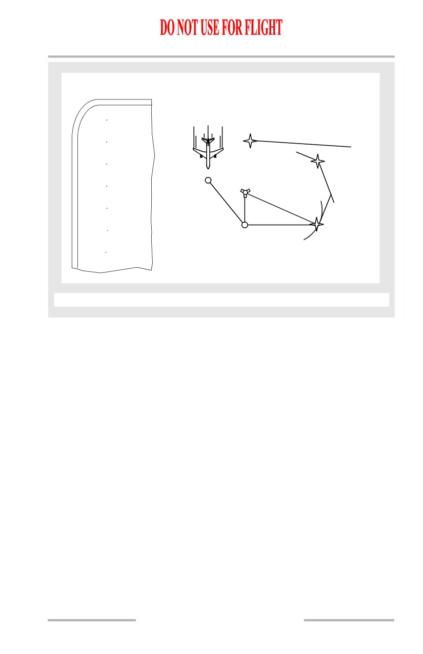
Altitude and course intercept conditional waypoints are displayed on the CDU
inside (parentheses) marks. The following diagram depicts conditional waypoints.
11.31.14
Flight Management, Navigation -
Flight Management System
Operation
Boeing 737 Operations Manual
EXAMPLE:
MEANING:
RTE LEGS
180
HDG
CDE
(1000)
140
HDG
BCD
(ABC180)
180` HDG
TO 1000'
280` FOR
90
HDG
VECTORS
TO CDE
(ABC-20)
090`R
20
HDG
ABC
(INTC)
020` HDG
340
140` HDG
TO INTC
TO 180`R
340` TO BCD
BCD
ABC180
090` HDG
280
HDG
ABC20
TO 20 DME
(VECTOR)
270
CDE
Note: All waypoints except BCD and CDE are examples of conditional waypoints.
Note: When (VECTOR) is the active leg and LNAV is not engaged, the FMC
automatically sequence to the next waypoint when within 3 nm of the next
leg. If (VECTOR) is the active waypoint and LNAV is engaged, the FMC
does not automatically sequence to the next waypoint. The next waypoint
becomes active only upon EXECution of the procedures for Proceeding
Direct To a Waypoint or Intercepting a Leg to a Waypoint.
Manually Entered Latitude/ Longitude Waypoint Names
Pilot defined waypoints entered as a latitude and longitude are displayed in a
five-character format. The first three characters are WPT followed by a two digit
sequence number. Latitude and longitude waypoints are entered with no space or
slash between the latitude and longitude entries. Leading zeroes must be entered.
All digits and decimal points (to 1/10 minute) must be entered unless the latitude
or longitude are full degrees. Examples:
• N47° W008° is entered as N47W008 and displayed as WPT01
• N47° 15.4’ W008° 3.4’ is entered as N4715.4W00803.4 and displayed as
WPT02.
11.31.15
Flight Management, Navigation -
Flight Management System
Operation
Boeing 737 Operations Manual
Manually Entered Place-Bearing/Distance or
Place-Bearing/Place-Bearing Waypoint Names
Waypoints entered as a place-bearing/distance or place-bearing/place-bearing
are identified by the first three characters of the entry followed by a two-digit
sequence number. Examples:
• SEA330/10 becomes SEA01
• SEA330/OLM020 becomes SEA02.
Manually Entered Along-Track Waypoint Names
Along-track waypoints are a special case of place-bearing/distance waypoints
applied to the current route. When a waypoint is desired on the route where none
exists, the along-track waypoint feature creates the desired waypoint without
creating a route discontinuity.
Along-track waypoints are entered using the waypoint name (the place), followed
by a slash and minus sign, for points before the waypoint, or no sign for points
after the waypoint, followed by the mileage offset for the newly defined waypoint.
The route course takes the place of the bearing which is not entered. The created
waypoint is then inserted over the original waypoint. The distance offset must be
less than the distance between the originating waypoint and next (positive value)
or preceding (negative value) waypoint. Latitude and longitude waypoints cannot
be used to create along-track waypoints. Examples:
• VAMPS/25 is 25 miles after VAMPS on the present route, and is
displayed as VAM01
• ELN/-30 is 30 miles before ELN on the present route, and is displayed as
ELN01.
Navigation Displays
The route is displayed on the navigation display in the map, map center, and plan
modes. The display color and format represent the following status:
• an inactive route is displayed as a cyan dashed line
• an activated but not yet executed route is displayed as a cyan dashed line
• the active route is displayed in magenta
• modifications to an active route are displayed as dashed white lines
• modified waypoints are displayed in white
• executed route offsets are displayed as a dashed magenta line.
Vertical Navigation (VNAV)
VNAV provides vertical profile guidance through the climb, cruise, and descent
phases of flight.
11.31.16
Flight Management, Navigation -
Flight Management System
Operation
Boeing 737 Operations Manual
Speed/Altitude Restrictions
VNAV controls the path and speed to comply with waypoint crossing restrictions.
Waypoint crossing restrictions are entered on the LEGS page waypoint line by
pushing the applicable key on the right side of the CDU. Barometric altitude
restrictions must be below the cruise altitude to be valid. Values entered as part of
a procedure and manually entered restrictions are shown in large font. FMC
predicted values do not act as restrictions, and are shown in small font.
[Option - With color]
A waypoint restriction is magenta when it is active. The restriction does not have
to be in line 1 to be active.
[Option - With color]
Modified waypoint restrictions are shaded white until they are executed. Speed
restriction entries require an altitude restriction at the same waypoint.
Waypoints can have altitude, airspeed or both airspeed/altitude restrictions.
All speed restrictions are considered by the FMC as at or below restrictions.
At or above altitude restrictions are entered with a suffix letter A (example: 220A).
At or below altitude restrictions are entered with a suffix letter B (example: 240B).
Mandatory altitude restrictions are entered without any suffix letter (example:
270).
Altitude restrictions that are between two altitudes are displayed with the lower
limit first, followed by a suffix letter A, then the upper limit, followed by a suffix
letter B (example: 220A240B).
11.31.17
Flight Management, Navigation -
Flight Management System
Operation
Boeing 737 Operations Manual
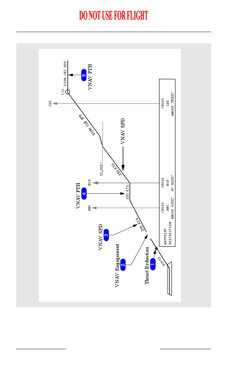
Takeoff and Climb
11.31.18
Flight Management, Navigation -
Flight Management System
Operation
Boeing 737 Operations Manual
1
Thrust Reduction
Climb thrust is selected by pushing the N1 switch.
[Option - With automatic thrust reduction after takeoff]
Climb thrust is selected by pushing the N1 switch or automatically upon reaching
the thrust reduction altitude.
[Option - With quiet climb]
When cutback mode is selected ON, the FMC calculates and commands a thrust
cutback at the required cutback altitude. A new N1 is calculated during climb and
normal climb thrust is restored at the RESTORE altitude.
2
VNAV Engagement
VNAV commands an airspeed increase to the planned climb speed profile, limited
by configuration.
3
VNAV Climb
The VNAV climb profile uses VNAV SPD at the default climb speed or pilot
selected climb speed to remain within all airspeed and altitude restrictions that are
part of the SID entered into the active route. Autothrottle uses selected climb
thrust limit.
Note: Selection of ENG OUT on the CLB page provides the crew with advisory
engine out performance information.
If the climb speed profile cannot achieve an altitude restriction, the UNABLE
NEXT ALTITUDE scratchpad message is shown.
4
Climb Restrictions
VNAV enters the VNAV PTH mode to remain within departure or waypoint
restrictions. Speed maintained during this time can be:
• procedure based speed restriction
• waypoint speed restriction
• default VNAV climb speed
• manually entered climb speed.
5
Top Of Climb (T/C)
The point where the climb phase meets the cruise altitude is called the top of
climb. Approaching this point, the FMC changes from the climb phase to the
cruise phase. The T/C is shown any time the FMC calculates a change from a
climb phase to a cruise phase, such as a step climb.
The T/C point is shown on the map as a green open circle with the label T/C.
October 15, 2001
11.31.19
Flight Management, Navigation -
Flight Management System
Operation
Boeing 737 Operations Manual
MCP Altitude Intervention
[Option]
[Option - With VNAV ALT]
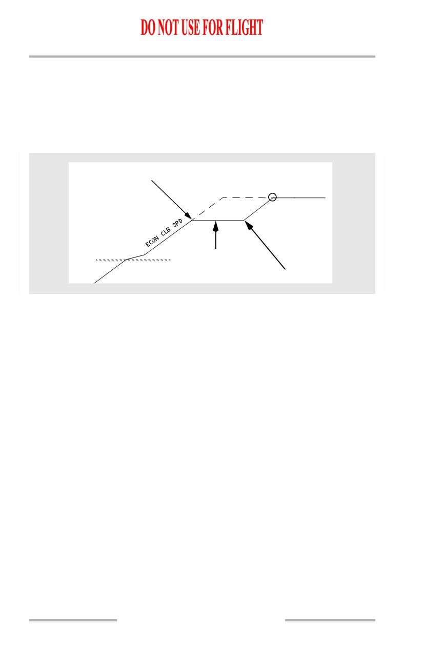
The altitude intervention switch may be used to resume climb after a temporary
level off.
[Option - With VNAV ALT]
Temporary Level Off
T/C
FL250
FL190
VNAV ALT
10,000'
Altitude Intervention switch
[Option - With VNAV ALT]
Whenever the airplane levels off at an MCP altitude that is not in the FMC, VNAV
ALT engages. In the illustration above, FMC cruise altitude is FL250 and the
clearance altitude, FL190, is set in the MCP. Pitch maintains altitude and thrust
maintains FMC target speed. In the illustration above, the speed after the
temporary level off would be ECON CLB SPEED.
[Option - With VNAV ALT]
To resume the climb, put the clearance altitude into the MCP altitude window and
push the altitude intervention switch. VNAV SPD engages. Pitch maintains FMC
speed and thrust increases to the climb limit. In the example, the airplane climbs
to FMC CRZ ALT and then levels off in cruise.
The altitude intervention switch may be used during climb or descent to delete
altitude restrictions between the current altitude and the MCP altitude. When level
at a restriction altitude, and cleared to a higher altitude prior to crossing the
restriction waypoint, reset the MCP altitude to the new clearance altitude and push
the altitude intervention switch.
11.31.20
October 15, 2001
Flight Management, Navigation -
Flight Management System
Operation
Boeing 737 Operations Manual
MCP altitude reset and
BCD
Altitude Intervention
T/C
switch pushed.
FL250
FL190
10,000'
CROSS
BCD
Altitude Restriction
AT FL190'
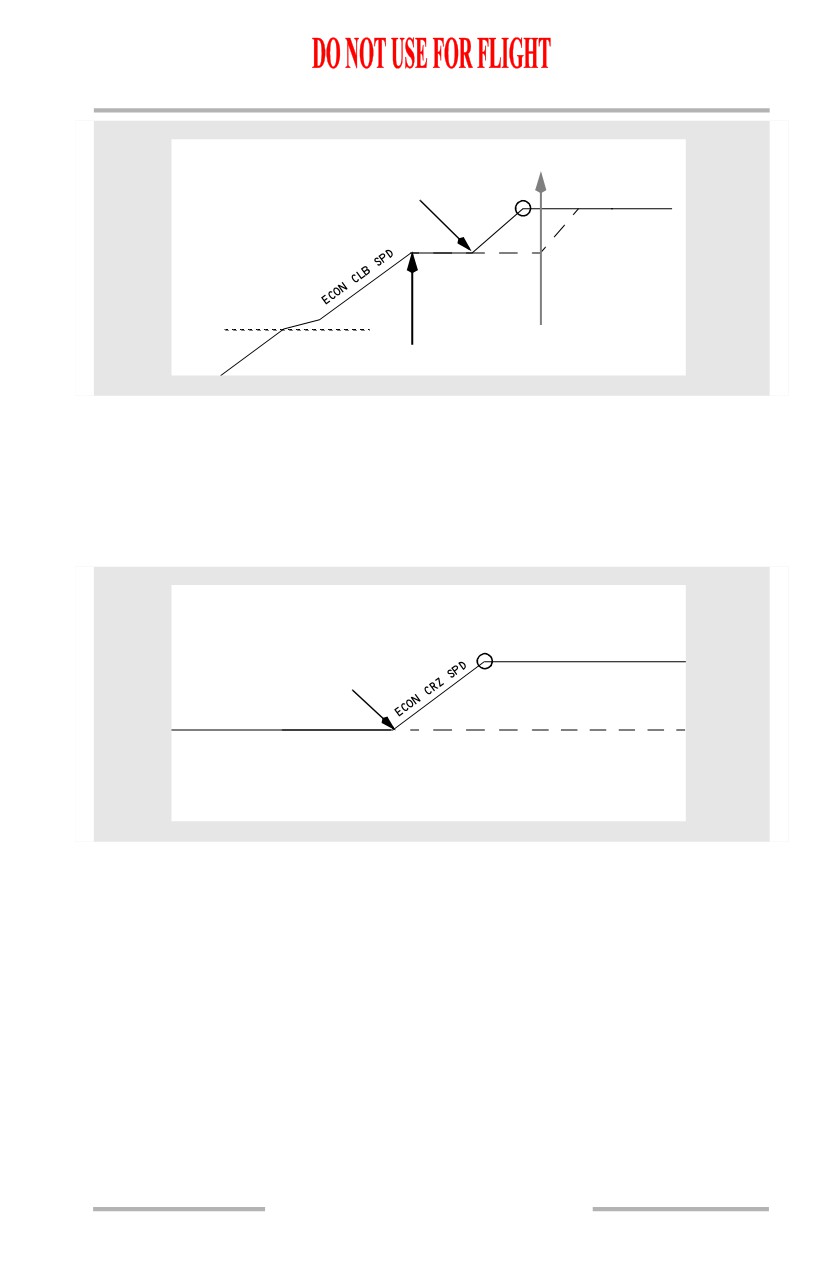
In the illustration above, the current altitude restriction is deleted and the airplane
continues VNAV climb to the cruise altitude. T/C moves to match the new climb
profile.
The altitude intervention switch may be used to increase cruise altitude. When
level at a cruise altitude, and then cleared to a higher cruise altitude, reset the MCP
altitude to the new cruise altitude and push the altitude intervention switch.
MCP altitude reset and
T/C
FL290
Altitude Intervention
switch pushed.
FL250
In the illustration above, the cruise altitude is increased and the airplane enters a
VNAV cruise climb at the economy cruise speed.
Altitude intervention cannot be used to decrease cruise altitude. Setting a lower
altitude then pushing the altitude intervention switch causes the FMC to enter an
early descent in the selected descent mode.
Cruise
At cruise altitude, the FMC sets cruise speed at the default or pilot entered speed
until reaching the top-of-descent (T/D) point. Alternate cruise speed options are:
• long range (LRC)
• flight crew entered speed.
October 15, 2001
11.31.21
Flight Management, Navigation -
Flight Management System
Operation
Boeing 737 Operations Manual
Cruise thrust is set as required to maintain level flight at the target speed, with the
autothrottle engaged. The FMC uses maximum range cruise speed if cost index is
set to zero.
Fuel and ETA predictions are based on a constant altitude cruise unless a step
climb altitude is entered.
Step Climb
If a step climb altitude is entered in the CRZ page STEP altitude, the FMC
calculates the point where the step climb should begin.
The distance and ETA to the next step point are shown on the CRZ and
PROGRESS pages. The next step point is shown on the map as a green open circle
with the label S/C.
MCP Speed Intervention
[Option]
VNAV PTH
CRZ
VNAV PTH
Altitude
VNAV PTH
Restriction
Altitude
Restriction
Speed Intervention Pitch Modes
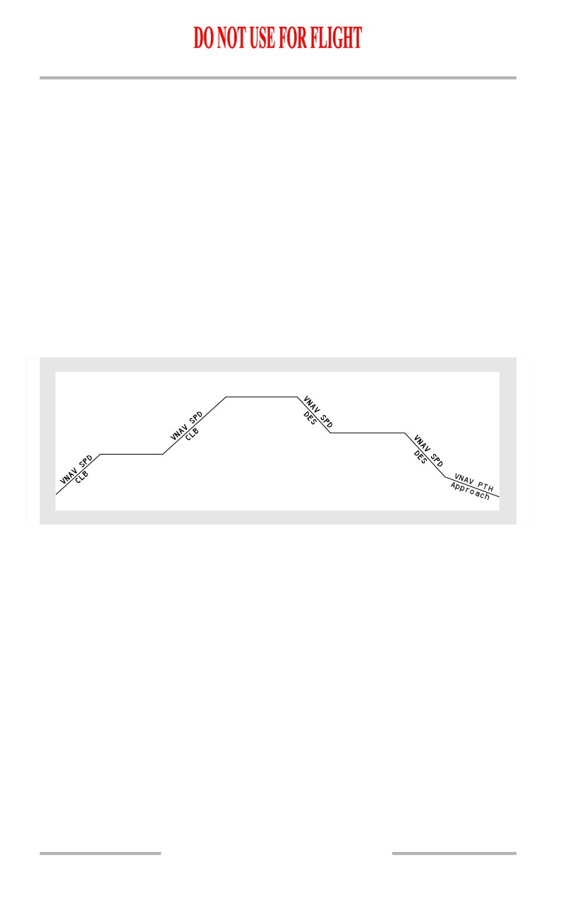
The above illustration shows VNAV mode for each phase of flight during speed
intervention.
With VNAV engaged, pushing the speed intervention switch enables speed
intervention. Speed intervention allows the flight crew to change airplane speed
with the IAS/MACH selector.
In a path descent, VNAV PTH changes to VNAV SPD during speed intervention.
In all other phases, the pitch mode remains the same. In VNAV PTH mode, thrust
controls speed; in VNAV SPD mode, pitch controls speed.
In approach phase during speed intervention, the pitch mode remains in VNAV
PTH after speed intervention is exited. The FMC shall remain in the current
vertical mode regardless of IAS MACH selector changes.
[Option - FMC U10.4 and later]
When speed intervention is exited the descent mode will switch back to path
mode.
11.31.22
October 15, 2001
Flight Management, Navigation -
Flight Management System
Operation
Boeing 737 Operations Manual
Descent
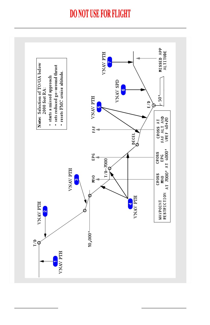
VNAV can perform a descent in either of two modes - path descent or speed
descent. During a path descent, the FMC uses idle thrust and pitch control to
maintain a vertical path, similar to a glideslope in three dimensions. During a
speed descent, the FMC uses idle thrust and pitch control to maintain a target
descent speed, similar to a level change descent.
Top Of Descent (T/D)
The point where the cruise phase changes to the descent phase is the top of
descent. The T/D point is shown on the map as a green open circle with the label
T/D. T/D is calculated from an end of descent (E/D) point.
Intermediate T/D points show on the map as green open circles with the label
T/D-XXXXX (altitude). Intermediate T/D points exist when path segments
between altitude restricted waypoints produce a level path segment. The
intermediate T/D point shows where the descent will resume.
End of Descent (E/D)
The FMC calculates a descent path based on airspeed restrictions, altitude
restrictions and the end of descent (E/D) point. The E/D point is shown on the map
as a green open circle with the label E/D. The E/D is the last of the following
which is not preceded by a lateral discontinuity:
• the runway threshold for approaches with a runway waypoint on the RTE
LEGS page, or
• the missed approach point for approaches not showing a runway waypoint
on the RTE LEGS page, or
• the lowest “at” altitude restriction if no arrival procedure is entered.
Entering an instrument arrival procedure provides an E/D point.
If there is no E/D point, FMC predictions assume a computed profile to 1000 feet
above the destination field elevation, at a position which will vary according to
selection of arrival procedures. The FMC will provide a slowdown profile for
approach. VNAV path descent is not available if there is no E/D point.
VNAV Descent and Approach Path
The descent path starts at the calculated top of descent (T/D) point and includes
waypoint altitude restrictions. The path is based on:
• idle thrust
• descent wind speed decreasing
• speedbrakes retracted
with decreasing altitude
• applicable target speed.
After the first “at” or “at or below” restriction, the path angle is level until
intercepting the idle thrust descent path to the next altitude constrained waypoint.
October 15, 2001
11.31.23
Flight Management, Navigation -
Flight Management System
Operation
Boeing 737 Operations Manual
[Option - FMC U10.2 and later]
Note: When passing top of descent following high speed cruise operation (within
approximately 6 knots of Vmo/Mmo, cost index of 100 or higher), VNAV
may revert to LVL CHG to prevent overspeed. Reduce airspeed to the
VNAV target descent speed prior to reengaging VNAV.
[Option - With geometric descent path]
After the first “at” or “at or below” restriction, the path angle is constant between
waypoints.
Normally, the target speed is economy speed above the airspeed restriction
altitude and 240 knots below that altitude, until deceleration for approach. VNAV
will not permit descent below the airspeed restriction altitude until the airspeed is
at or below the restricted value plus ten knots. The start and end of the airport
speed restriction deceleration segment is shown on the map as a green open circles
with no labels.
The descent path assumes deceleration to reach the final approach fix (FAF), or
the glideslope intercept point at VREF 40+20 knots.
Target speeds are changed by entries on the LEGS or DESCENT pages. Wind and
thrust assumptions are changed on the DES FORECASTS page.
Deceleration points show on the map as green open circles with the label DECEL.
Deceleration points show prior to:
• airspeed constrained waypoints
• holding patterns
• approach flap extension.
If more than one deceleration segment exists in the flight plan, only the next
deceleration point shows. Deceleration points can also show prior to cruise
holding patterns or other speed reductions.
[Option - With VNAV ALT]
During descent, VNAV ALT engages if the airplane levels at an MCP altitude not
in the FMC.
VNAV Path Descent
An E/D point must be defined in order to accomplish a path descent. It may be
defined manually or by the selection of an arrival procedure.
The FMC defaults to the path descent mode for planning purposes. If the
necessary information for a path descent is not available by the time the airplane
reaches the T/D point, the FMC will revert to the speed descent mode.
The path descent normally begins automatically at the calculated T/D point,
provided the MCP altitude is reset for the descent. If descent is not initiated by the
T/D, a path descent may not be available. At the T/D, the FMC commands idle
thrust and pitch to follow the descent path.
11.31.24
Flight Management, Navigation -
Flight Management System
Operation
Boeing 737 Operations Manual
The descent complies with waypoint altitude restrictions by following the
calculated vertical path.
Note: A path descent uses the target speed for planning purposes only. There is
no attempt to maintain the target speed.
A path descent will automatically revert to a speed descent, or VNAV will
disengage, if all required parameters are not maintained during descent.
Note: When descending in VNAV PTH, the FCC will disengage VNAV and
switch to LVL CHG if actual speed becomes equal to or slightly less than
the minimum speed, denoted by the underspeed limiting symbol in the
MCP IAS/Mach window. This can also happen in turbulence or gusty
conditions when the minimum speed may momentarily increase due to G
loading. See section 4.20, Minimum Speed Reversion.
The FMC uses a special program called “Energy Compensation” at certain times
during an ACT PATH DES. This program goes into effect when the MCP has been
temporarily set to an altitude above the planned descent path. The airspeed cursor
will slowly move toward a slower airspeed while the “TARGET” speed on the
FMC remains constant. The airspeed reduction improves the capability of
recapturing the planned descent path. When the airplane is cleared to resume the
descent, the airspeed will slowly build up to the FMC target speed as the airplane
recaptures the planned descent path.
The CDU message DRAG REQUIRED is displayed if an unexpected tailwind
results in a significant increase in airspeed to maintain path. The CDU message
DES PATH UNACHIEVEABLE is displayed if the FMC determines that the
planned descent profile cannot be accomplished. VNAV disengages if a limit
speed will be exceeded.
[Option - FMC U10.3]
A path descent must be initiated while within the allowable cross-track error for
LNAV, however LNAV may be disengaged during descent while remaining in the
path mode. To maintain a path descent under these conditions, the airplane must
remain within a distance equal to twice the RNP from the LNAV course. If this
distance is exceeded, VNAV will change to speed descent if no vertical angle is
specified for the current leg. VNAV will disengage if there is a vertical angle
specified and LNAV is not engaged.
[Option - FMC U10.4 and later]
A path descent must be initiated while within the allowable cross-track error for
LNAV, however LNAV may be disengaged during descent while remaining in the
path mode. To maintain a path descent under these conditions, the airplane must
remain within a distance equal to twice the RNP from the LNAV course. VNAV
will remain in path regardless of cross-track.
11.31.25
Flight Management, Navigation -
Flight Management System
Operation
Boeing 737 Operations Manual
VNAV Cruise and Path Descent Profile (Nonprecision Approach)
11.31.26
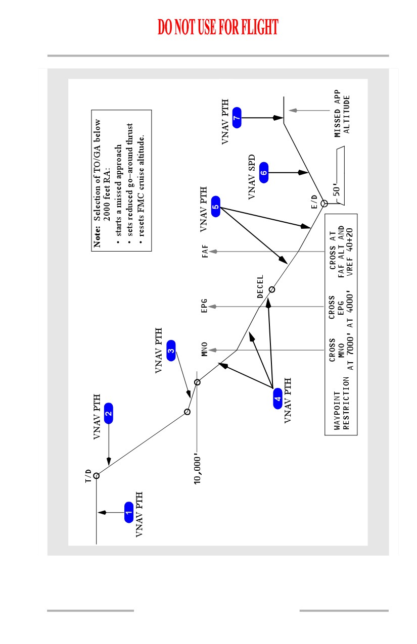
Flight Management, Navigation -
Flight Management System
Operation
Boeing 737 Operations Manual
[Option - With geometric descent path]
11.31.27