Boeing 737 - 600/700/800/900. Operations Manual (1997 year) - page 49
Flight Instruments, Displays -
EFIS Instruments (PFD) -
Controls
Boeing 737 Operations Manual
4
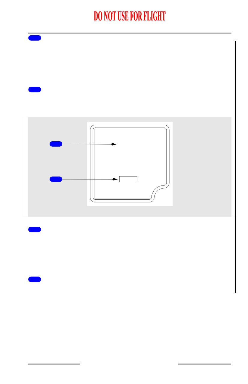
Display Brightness Switches
Push -
•
+ increases display brightness
•
- decreases display brightness
5
Airplane Symbol
Indicates airplane attitude with reference to the horizon.
6
Airspeed Indications
Indicates current airspeed when above 30 knots.
7
Attitude Reset (ATT RST) Switch
Push and hold at least two seconds
• aligns horizon with the airplane symbol
• reset takes approximately ten seconds
8
Hectopascal/Inch (HP/IN) Switch
Push - changes the units of the barometric reference.
9
Barometric Setting
Indicates the barometric setting selected with the barometric selector.
STD is displayed when selected with the barometric selector.
10
Ambient Light Sensor
Automatically adjusts display intensity for ambient lighting condition.
11
Glideslope Pointer and Deviation Scale
The glideslope pointer indicates glideslope position relative to the airplane.
• the pointer is in view when the glideslope signal is received
• the scale is in view when the APP mode is selected
• the pointer and scale are removed when the BCRS mode is selected
12
Current Altitude
13
Localizer Pointer and Deviation Scale
The localizer pointer indicates localizer position relative to the airplane.
• the pointer is in view when the localizer signal is received
• the scale is in view when either the APP or BCRS mode is selected
10.16.12
Flight Instruments, Displays -
EFIS Instruments (PFD) -
Controls
Boeing 737 Operations Manual
14
Barometric (BARO) Selector
Rotate - changes barometric setting
Push -
• selects standard barometric setting (29.92 inches Hg/1013 HPA)
• if STD is displayed, selects the preselected barometric setting
15
Heading Indication
Displays airplane heading.
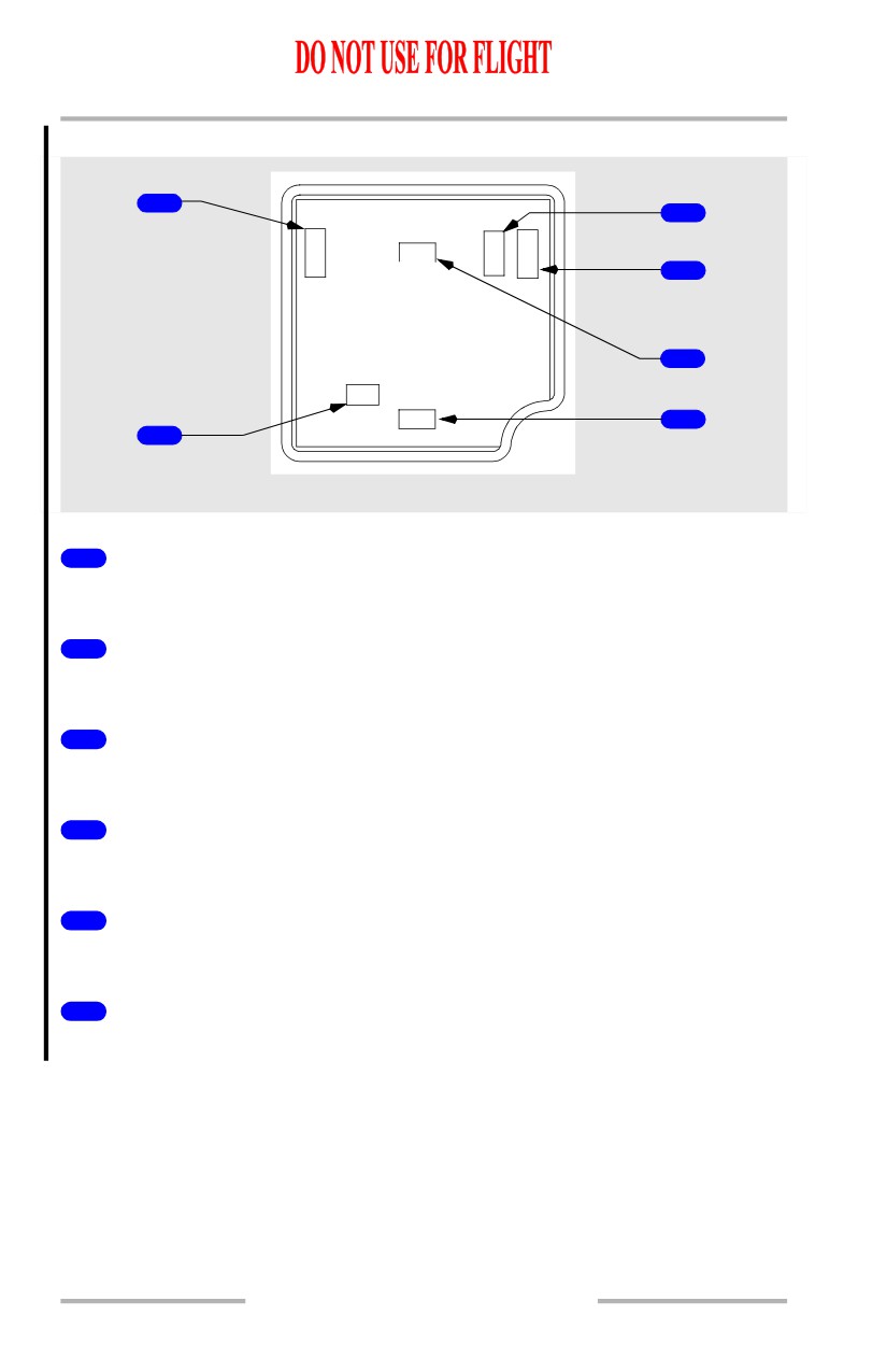
ISFD Messages
1
WAIT ATT
2
INIT 90s
ISFD
1
Attitude Messages
Indicates attitude display status.
• ATT:RST (amber) - attitude must be reset using the attitude reset switch
• ATT 10s (amber) - 10 second attitude realignment in progress
• WAIT ATT (amber) - indicates temporary self correcting loss of attitude
2
Initialization Message
INIT 90s (amber) - 90 second initialization in progress.
10.16.13
Flight Instruments, Displays -
EFIS Instruments (PFD) -
Controls
Boeing 737 Operations Manual
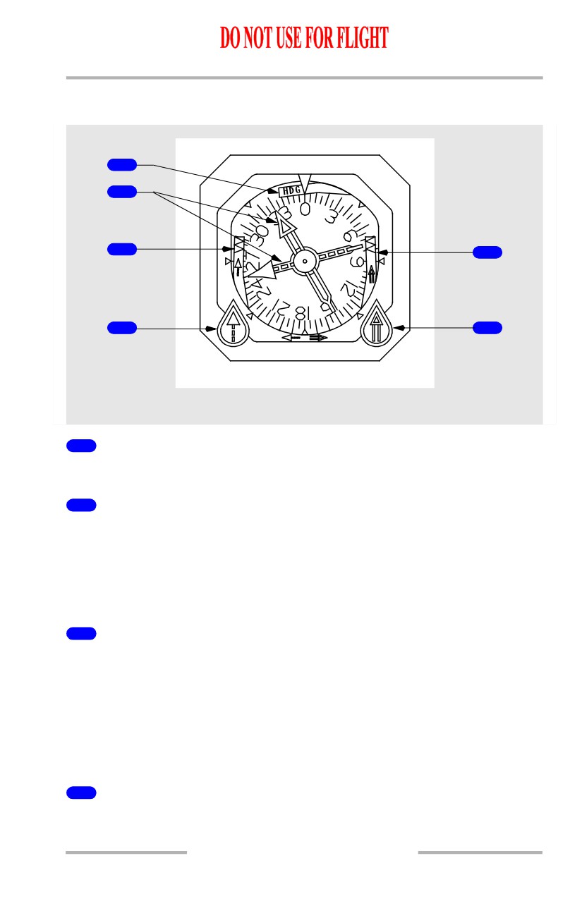
ISFD Failure Flags
1
3
S
G
A
P
ATT
/
L
D
S
T
4
5
LOC
HDG
6
2
ISFD
1
Airspeed flag
Airspeed information has failed.
2
ILS localizer failure flag
ILS localizer has failed.
3
ILS glideslope failure flag
ILS glideslope has failed.
4
Altitude flag
Altitude information has failed.
5
Attitude flag
Attitude information has failed.
6
Heading flag
Heading data has failed.
10.16.14
Flight Instruments, Displays -
EFIS Instruments (PFD) -
Controls
Boeing 737 Operations Manual
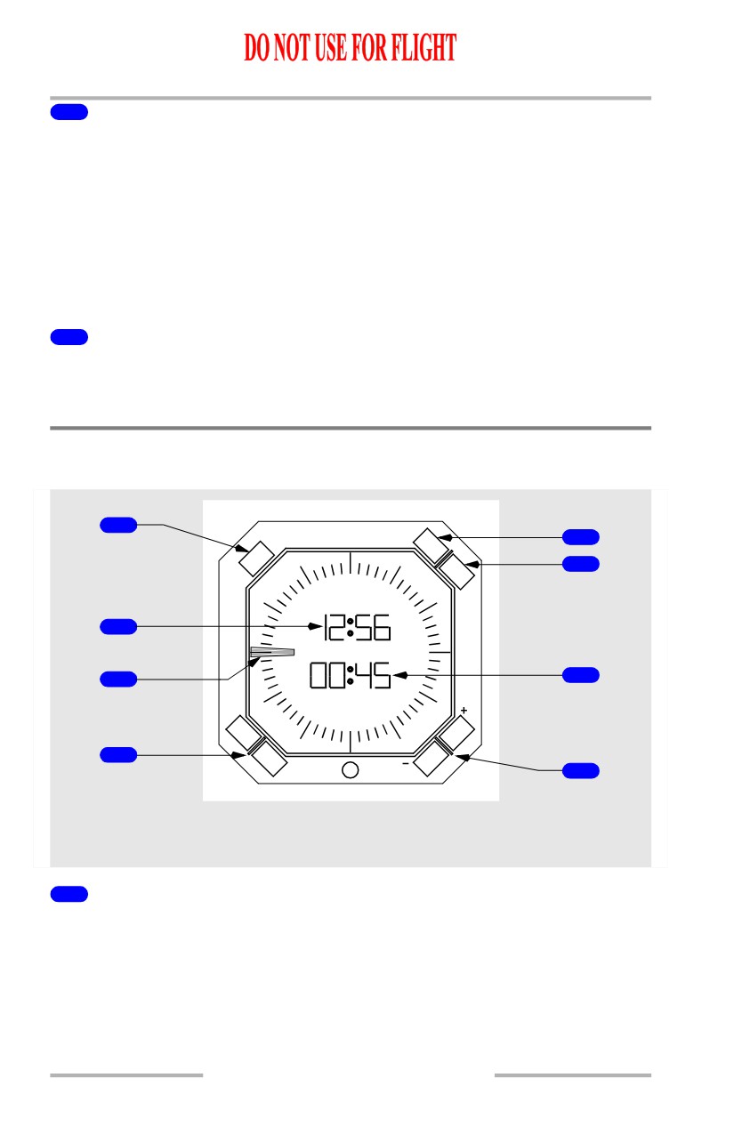
Standby Radio Magnetic Indicator
[Option - Dual ADF]
1
2
3
5
V
V
O
O
R
R
4
6
ADF
ADF
CENTER INSTRUMENT PANEL
1
Heading Warning Flag
The compass signal from the air data inertial reference system is lost.
2
Bearing Pointers
• narrow pointer uses signals from the VHF NAV receiver No. 1 or ADF
receiver No. 1
[Option - Dual ADF]
• wide pointer uses signals from the VHF NAV receiver No. 2 or ADF
receiver No. 2.
3
Bearing Pointer No. 1 Warning Flag
VOR mode:
• RMI power failure
• VHF NAV signal unreliable.
ADF mode:
• RMI power failure
• ADF failure or signal unreliable.
4
VOR/ADF Bearing Pointer No. 1 Switch
ROTATE - selects VOR or ADF for the bearing pointer.
10.16.15
Flight Instruments, Displays -
EFIS Instruments (PFD) -
Controls
Boeing 737 Operations Manual
5
Bearing Pointer No. 2 Warning Flag
VOR mode:
• RMI power failure
• VHF NAV signal unreliable.
[Option - Dual ADF]
ADF mode:
• RMI power failure
• ADF failure or signal unreliable.
6
VOR/ADF Bearing Pointer No. 2 Switch
[Option - Dual ADF]
ROTATE - selects VOR or ADF for the bearing pointer.
Clock
[Option - GPS capable]
1
CHR
TIME/DATE
5
MAN
6
UTC
60
SET
TIME
50
10
2
DAY MOYR
3
7
40
20
ET CHR
ET
RUN
HLD
30
4
RESET
8
LEFT and RIGHT FORWARD
PANELS
1
Chronograph (CHR) Control
PUSH -
• controls the start, stop and reset functions of the CHR display and second
hand with successive pushing
• overrides any existing ET display.
10.16.16
Flight Instruments, Displays -
EFIS Instruments (PFD) -
Controls
Boeing 737 Operations Manual
2
Time/Date Indicator
• displays UTC or manual time (hours, minutes) when time is selected with
the time/date pushbutton
• alternately displays day-month and year when date is selected with the
time/date pushbutton.
3
Chronograph Second Hand
• indicates chronograph seconds
• controlled by the CHR control.
4
Elapsed Time (ET) and RESET Pushbutton
Controls the elapsed time function:
• select the ET pushbutton once to run the elapsed time
• select the ET pushbutton again to hold the elapsed time
• select the RESET pushbutton to set the elapsed time to 0.
The RUN or HLD symbol is displayed on the lower left part of the LCD display.
5
TIME/DATE Pushbutton
Controls the time/date function:
• select the TIME/DATE pushbutton once to see UTC time
• select the TIME/DATE pushbutton again to see UTC date
• select the TIME/DATE pushbutton again to see manual time
• select the TIME/DATE pushbutton again to see manual date.
The UTC or MAN symbol is displayed on the upper right part of the LCD display.
In MAN mode, clock time and date come from the clock. In UTC mode, clock
time and date come from the global positioning system.
6
SET Pushbutton
Controls the setting of manual time and date:
With manual time displayed:
• select the SET pushbutton once and the hours flash, use the plus or minus
pushbutton to adjust the hours
• select the SET pushbutton again and the minutes flash, use the plus or
minus pushbutton to adjust the minutes
• select the SET pushbutton again to run the time.
10.16.17
Flight Instruments, Displays -
EFIS Instruments (PFD) -
Controls
Boeing 737 Operations Manual
With manual date displayed:
• select the SET pushbutton once and the day flashes, use the plus or minus
pushbutton to adjust the day
• select the SET pushbutton again and the month flashes, use the plus or
minus pushbutton to adjust the month
• select the SET pushbutton again and the year flashes, use the plus or
minus pushbutton to adjust the year
• select the SET pushbutton again to run the date.
Note: A delay greater than one minute while setting the time or date results in the
clock reverting to the previous time/date setting.
7
Elapsed Time (ET)/Chronograph Indicator
• displays elapsed time (hours, minutes) or chronograph minutes
• the chronograph display replaces the elapsed time display
• elapsed time continues to run in the background and displays after the
chronograph is reset.
8
Plus (+) and Minus (-) Pushbuttons
Used to set the manual time and date:
• select the + pushbutton to increase the value
• select the - pushbutton to decrease the value.
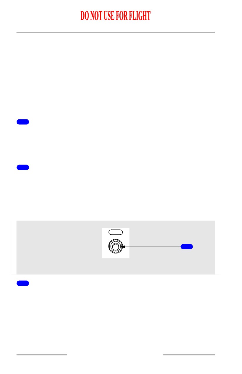
Clock Switch
[Option]
CLOCK
1
GLARESHIELD PANEL
1
Clock Switch
Operates the same as the chronograph (CHR) control.
10.16.18
Flight Instruments, Displays -
EFIS Instruments (PFD) -
Controls
Boeing 737 Operations Manual
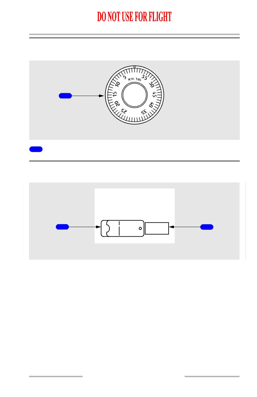
Timer
[Option]
0
u
1
AFT OVERHEAD PANEL
1
Mechanical Timer
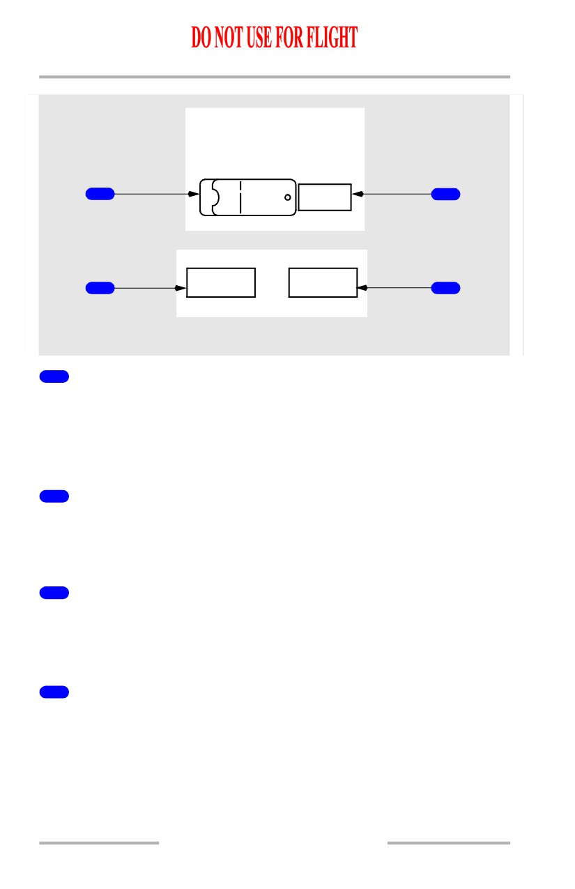
Flight Recorder
[Option - Without QAR lights]
FLIGHT RECORDER
TEST NORMAL
1
OFF
2
AFT OVERHEAD PANEL
10.16.19
Flight Instruments, Displays -
EFIS Instruments (PFD) -
Controls
Boeing 737 Operations Manual
[Option - With QAR lights]
FLIGHT RECORDER
TEST NORMAL
1
OFF
2
OQAR
OQAR FAIL
3
DISC FULL
4
AFT OVERHEAD PANEL
1
Flight Recorder Test Switch
NORMAL (guarded position) -
• in flight - the recorder operates anytime electrical power is available
• on the ground - either engine must also be operating.
TEST - powers the flight recorder on the ground.
2
OFF Light (amber)
ILLUMINATED -
• indicates the recorder is not operating or the test is invalid
• may indicate power failure, loss of input data, or electronic malfunction.
3
Optical Quick Access Recorder (OQAR) Disc Full (blue)
[Option - QAR lights]
ILLUMINATED -
• indicates the quick access recorder is full
4
Optical Quick Access Recorder (OQAR) FAIL (blue)
[Option - QAR lights]
ILLUMINATED -
• indicates the quick access recorder has failed
10.16.20
Boeing 737 Operations Manual
Flight Instruments, Displays
Chapter 10
Head-Up Display System - Controls
Section 17
Head-Up Display Control Panel Controls - Flight Instrument
Displays
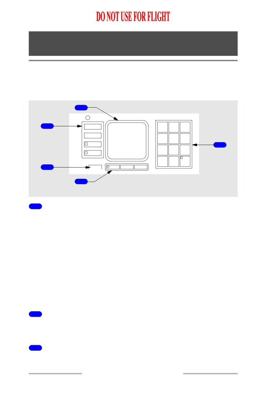
The HUD control panel controls modes of operation, display values, and system
test and status information.
2
1
MODE
1
2
3
H
STBY
4
5
6
G
S
RWY
5
7
8
9
G/S
ENTER
0
TEST
3
FAULT
CLR BRT + DIM -
4
AFT ELECTRONIC PANEL
1
Mode/Function Keys
Push - selects mode or allows data entry:
• MODE - selects desired mode from available modes on the standby
display line.
• STBY - selects standby mode.
• RWY - used to enter runway length and elevation or to toggle between
entered values. Select once to enter runway length, select again to enter
runway elevation. Use the DIM - (minus) key to enter negative values.
• G/S - used to enter the glideslope angle for the landing runway.
Note: Values entered using the mode/function keys are stored in the HUD
computer. If a power interruption should occur, the last mode and value
will be displayed once power is restored.
2
Control Panel Display
Displays information entered using the mode/function keys. Refer to Section 12,
Head-Up Display System - Displays.
3
FAULT Light
Illuminated (amber) - HUD BITE fault.
10.17.1
Flight Instruments, Displays -
Head-Up Display System -
Controls
Boeing 737 Operations Manual
4
Clear and Brightness Keys
CLR - used to clear all symbology from the combiner display. Symbology can be
re-displayed by selecting CLR again, changing modes, or entering TEST. CLR
can also be used as a backspace key during data entry and TEST operations.
BRT + (plus) - used to manually increase control panel display intensity.
DIM - (minus) - used to manually decrease control panel display intensity.
Note: Display brightness is adjusted automatically based on ambient light
measured by a sensor located in the upper left corner of the control panel.
5
Numeric Keys
Push -
•
0 through 9 - puts selected number in display
• ENTER - used to enter selected values
• TEST - used by maintenance for system tests and troubleshooting.
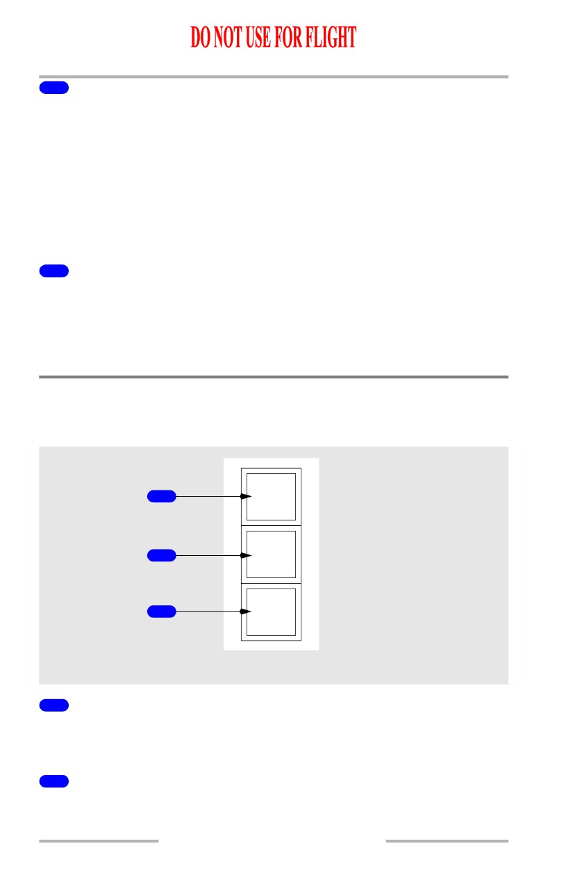
HUD Annunciator Panel
[Option - Model 2350]
[Option - 3-light annunciator panel]
1
AIII
APCH
2
WARN
3
FLARE
RIGHT FORWARD PANEL
1
AIII Light
Illuminated (green) - AIII mode is active and all required systems and equipment
are valid.
2
APCH WARN Light
Illuminated (red) - system or approach conditions out of tolerance.
10.17.2
Flight Instruments, Displays -
Head-Up Display System -
Controls
Boeing 737 Operations Manual
3
FLARE Light
Illuminated (green) - HUD system derived flare guidance is active.
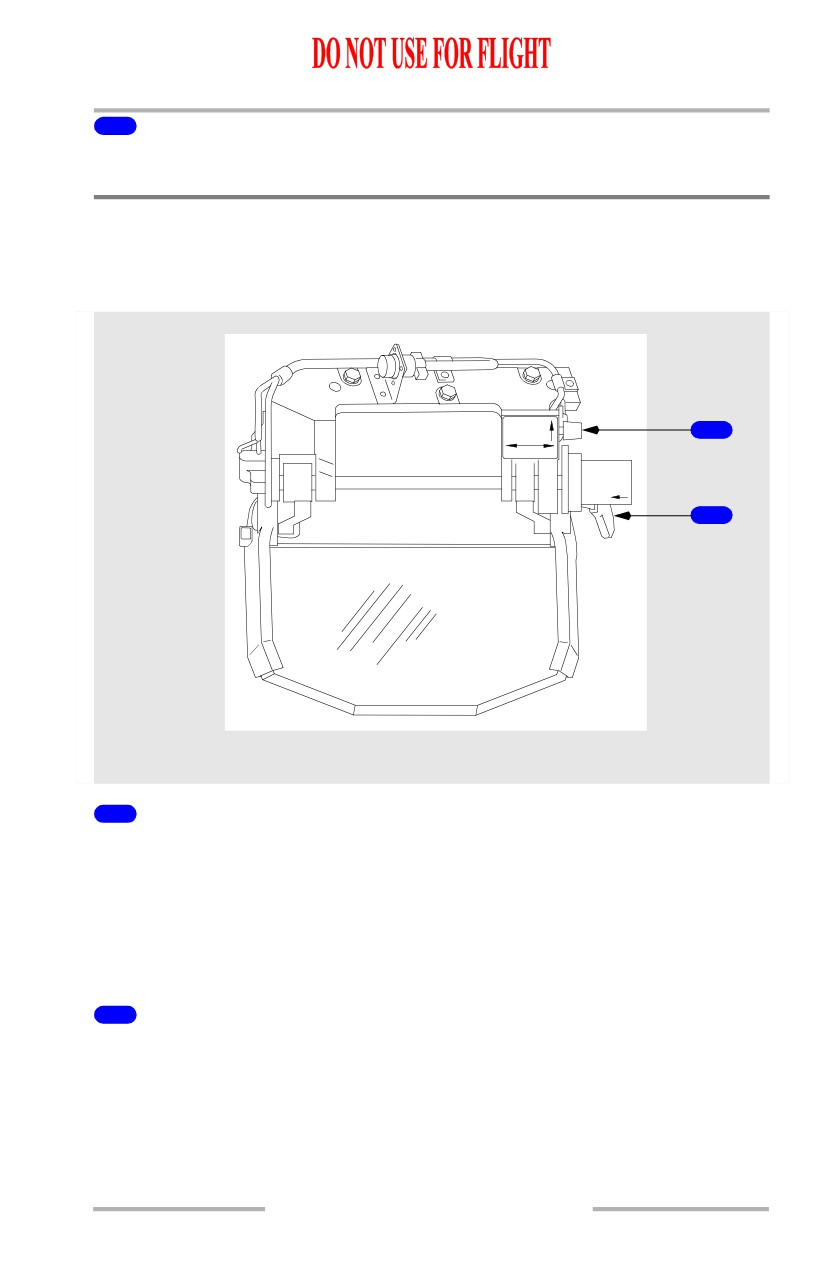
Combiner Controls
[Option - Model 2350]
Brightness and Stow Controls
HUD
BRT
1
MAN AUTO
DEPRESS
LEVER
TO
STOW
2
OVERHEAD FLIGHT DECK
1
Brightness Control Knob
MAN - push knob in for manual brightness adjustment.
AUTO - pull knob out for automatic brightness adjustment. Display intensity
varies based on ambient light detected by a sensor on the combiner.
HUD BRT - rotate knob clockwise to increase display intensity. Rotate knob
counter-clockwise to decrease display intensity.
2
Stow Lever
Push lever against the stow shaft housing and rotate vertically in the desired
direction.
10.17.3
Flight Instruments, Displays -
Head-Up Display System -
Controls
Boeing 737 Operations Manual
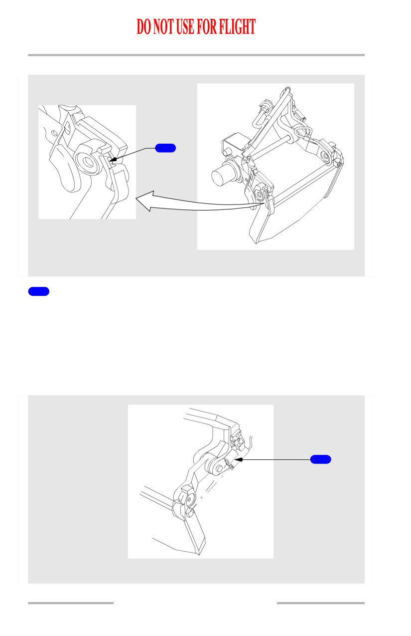
Combiner Breakaway
1
OVERHEAD FLIGHT DECK
1
Breakaway Reset Lever
Used to release the combiner from the break away position.
CAUTION: The breakaway feature allows the combiner to be displaced
forward of its normal operating position. Do not allow the
combiner to spring back from the full or near full breakaway
position on its own, as this could cause damage to the combiner.
Combiner Alignment
1
OVERHEAD FLIGHT DECK
10.17.4
Flight Instruments, Displays -
Head-Up Display System -
Controls
Boeing 737 Operations Manual
1
Combiner Alignment Detector
Ensures correct combiner alignment with the overhead unit.
Consists of an infra-red emitter, mirror and detector.
Note: In the IMC or VMC modes, an out of tolerance condition results in an
ALIGN HUD message on the combiner display. Gently push the combiner
in the breakaway direction (forward) and release it to remove the message.
If the message cannot be removed, the IMC or VMC mode should not be
used.
10.17.5
Flight Instruments, Displays -
Head-Up Display System -
Controls
Boeing 737 Operations Manual
Intentionally
Blank
10.17.6
Boeing 737 Operations Manual
Flight Instruments, Displays
Chapter 10
EFIS/Map System Description
Section 20
Introduction
The common display system (CDS) supplies information to the flight crew on six
flat panel liquid crystal display units (DUs). The outboard and inboard display
units present all primary flight and navigation information. Engine and system
data are normally shown on the upper display unit. The lower display unit serves
as a spare.
Detailed information on the following subjects is found in other sections of this
chapter:
• Electronic Flight Instrument System (EFIS) - Section 30
• Navigation display - Section 40.
Display Brightness Control
Adjustment of the brightness of each DU is controlled by a combination of light
sensors and brightness controls. Two remote light sensors, located left and right
on the top of the glareshield, compensate for the amount of ambient light entering
through the flight deck windows and adjust the brightness of the related DUs.
Each DU also has an integral light sensor which provides automatic control of
brightness as a function of ambient light striking the face of the DU. Brightness
controls are used by the pilot to further adjust the intensity of each display unit.
10.20.1
Flight Instruments, Displays -
EFIS/Map System Description
Boeing 737 Operations Manual
DISPLAYS SOURCE Panel
DISPLAYS
SOURCE
CONTROL PANEL
AUTO
ALL
ALL
BOTH
BOTH
ON 1
ON 2
ON 1
ON 2
NORMAL
CAPT
CAPT
F/O
F/O
ENGINE
OUTBD
INBD
INBD
OUTBD
DEU 1
DEU 2
AIRPLANE SENSORS AND SYSTEMS
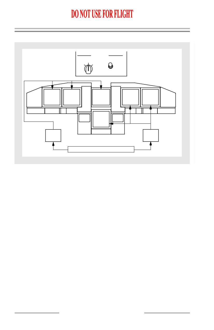
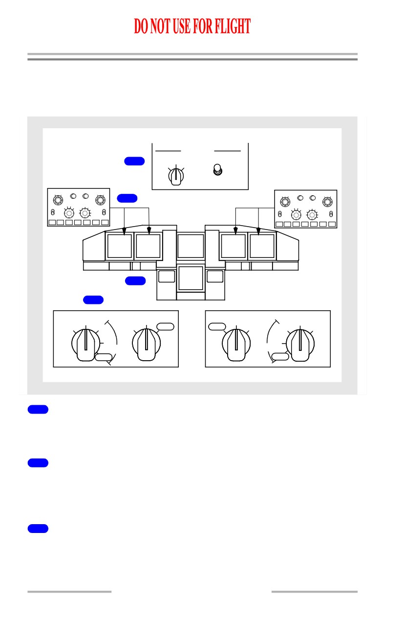
The DISPLAYS source panel, located on the forward overhead panel, contains
source controls for the display electronic units (DEUs) and EFIS control panels.
Two DEUs receive data from sensors and airplane systems and supply data to the
DUs. During normal operation, with the display SOURCE selector in the AUTO
position, DEU1 supplies data to the Captain outboard, Captain inboard and upper
DUs while DEU2 supplies data to the First Officer outboard, First Officer inboard
and lower DUs. If a DEU fails, the remaining DEU automatically supplies data to
all six displays. This prevents the loss of navigation information.
The display SOURCE selector, used on the ground for maintenance purposes,
allows manual selection of either DEU1 or DEU2 for all six display units. If the
displays are automatically or manually switched to a single DEU source, a
“DSPLY SOURCE” annunciation illuminates above both pilot’s altimeters.
The CONTROL PANEL select switch determines which EFIS control panel
controls the pilots’ display functions. With the switch positioned to either BOTH
ON 1 or BOTH ON 2, the selected EFIS control panel provides inputs for both sets
of pilot displays. When in the NORMAL position, a “DISPLAYS CONTROL
PANEL” annunciation illuminates on the pilot’s altimeters and indicates a failure
of the associated EFIS control panel.
10.20.2
Flight Instruments, Displays -
EFIS/Map System Description
Boeing 737 Operations Manual
EFIS Control Panels
The EFIS control panels, located on the glareshield, control display options,
mode, and range for the related pilot’s displays. Refer to the EFIS and navigation
display sections of this chapter for detailed information.
If an EFIS control panel fails, the displays can be controlled by the remaining
control panel.
Display Select Panel
The display select panel, located on the left and right forward panels, controls the
displays on the inboard, outboard and lower DUs. Normal operation is all selectors
in the NORMAL position. The pilots’ outboard and inboard DUs display primary
flight and navigation data and the upper DU displays engine data.
If a DU fails, automatic display switching ensures critical information remains
available to the pilots at all times. If the system detects an operational failure on
an outboard DU, the compact EFIS format automatically moves to the inboard DU
and the failed outboard DU blanks. If the system detects a failure on an inboard
DU, the compact EFIS format automatically moves to the outboard DU and the
failed inboard DU blanks. If the upper DU fails, the engine display automatically
moves to the lower DU.
Manual control of display formats is provided for undetected failures. The
outboard rotary switch on the display select panel controls the formats displayed
on either the outboard or inboard DUs. The inboard rotary switch controls the
display format shown on the lower DU.
10.20.3
Flight Instruments, Displays -
EFIS/Map System Description
Boeing 737 Operations Manual
Display Selection and Control Examples
The following examples show display selections.
Normal Display Configuration
DISPLAYS
SOURCE CONTROL PANEL
1
AUTO
ALL
ALL
BOTH
BOTH
ON 1
ON 2
ON 1
ON 2
NORMAL
MINS
RADIO BAROF
PV
MTRS
BAROIN HPA
MINS
PV
MTRS
BARO
RADIO BAROF
IN HPA
RST
STD
2
RST
STD
VOR1
APPVOR MAP
PLN
2040
80
VOR
2
VOR MAP
PLN
10
160
VOR1
APP
2040
80
160
VOR2
OFF
CTR
5
TFC
320
OFF
OFF
10
ADF1
640
ADF2
ADF1
CTR
5
TFC
320640
OFFADF2
WXR STA WPT ARPT DATA POS TERR
WXR STA WPT ARPT DATA POS TERR
CAPT
CAPT
F/O
F/O
ENGINE
OUTBD
INBD
INBD
OUTBD
4
3
MAIN PANEL DUs
LOWER DU
LOWER DU
MAIN PANEL DUs
NORM
NORM
NORM
NORM
OUTBD
ENG
ENG
INOP
INOP
ENG
ENG
OUTBD
PFD
PRI
PRI
PRI
PRI
PFD
PFD
PFD
INBD
INBD
INOP
INOP
1
DISPLAYS Source Panel
The display SOURCE select switch is in AUTO and the CONTROL PANEL
select switch is in NORMAL.
2
EFIS Control Panel
The left EFIS control panel controls the Captain outboard and inboard display
units. The right EFIS control panel controls the First Officer outboard and inboard
display units.
3
Display Select Panel
All selectors are in NORMAL.
10.20.4
Flight Instruments, Displays -
EFIS/Map System Description
Boeing 737 Operations Manual
4
Display Units
The pilots’ outboard and inboard DUs show the normal EFIS/MAP displays.
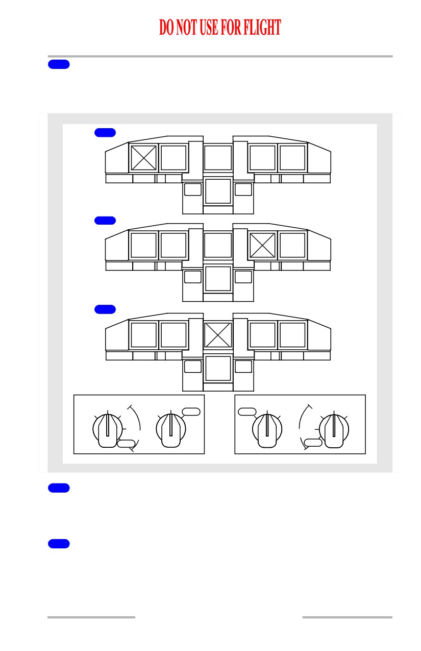
Display Unit Failure Automatic Switching
1
COMPACT
F/O
F/O
FORMAT
ENGINE
INBD
OUTBD
2
APT
CAPT
COMPACT
OUTBD
INBD
ENGINE
FORMAT
3
CAPT
CAPT
F/O
F/O
OUTBD
INBD
INBD
OUTBD
ENGINE
MAIN PANEL DUs
LOWER DU
LOWER DU
MAIN PANEL DUs
NORM
NORM
NORM
NORM
OUTBD
ENG
ENG
INOP
INOP
ENG
ENG
OUTBD
PFD
PRI
PRI
PRI
PRI
PFD
PFD
PFD
INBD
INBD
INOP
INOP
1
Outboard Display Unit Fails
If an outboard display unit fails, the compact EFIS format is automatically
displayed on the inboard display unit and the outboard display unit blanks.
2
Inboard Display Unit Fails
If an inboard display unit fails, the compact EFIS format is automatically
displayed on the outboard display unit and the inboard display unit blanks.
10.20.5