Boeing 737 - 600/700/800/900. Operations Manual (1997 year) - page 46
Flight Instruments, Displays -
PFD/ND - Displays
Boeing 737 Operations Manual
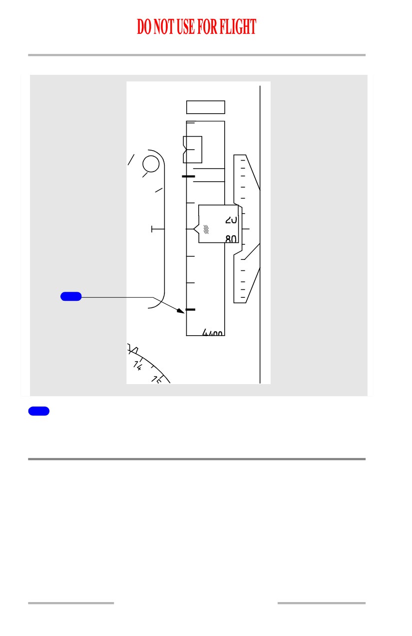
Altitude Disagree Alert
M
1550
5100
5200
6
OM
5
000
2
1
1463M
4
800
1
4600
2
1
6
ALT
1000
BARO
DISAGREE
450
1011 HPA
1
Altitude Disagree Alert (amber)
Indicates the Captain’s and F/O’s altitude indications disagree by more than 200
feet for more than 5 continuous seconds.
Navigation Displays - MAP Mode
Note: Refer to section 41 of this chapter for a detailed explanation of the
navigation symbology shown on the following pages.
10.11.36
Flight Instruments, Displays -
PFD/ND - Displays
Boeing 737 Operations Manual
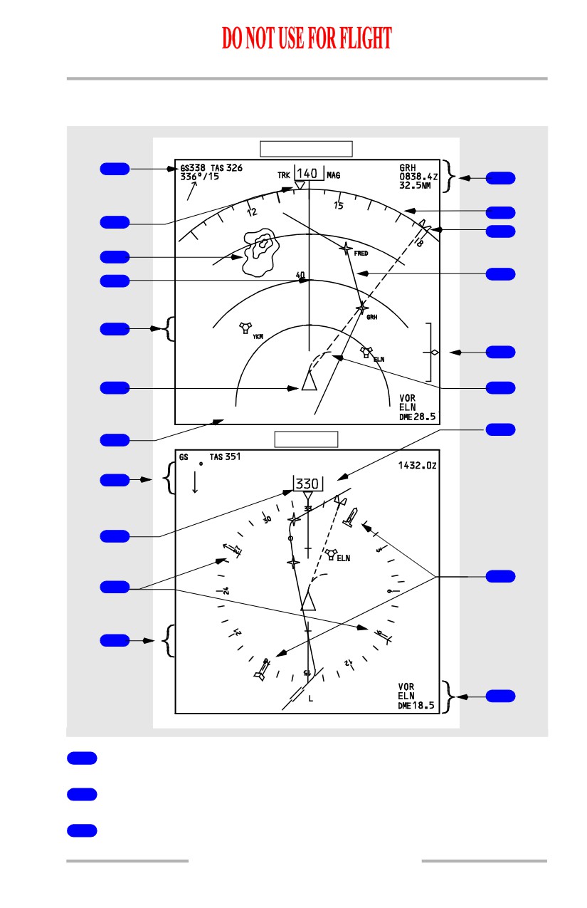
Expanded and Center MAP Modes
[Option - Track-up display, weather radar range arcs, dual FMC, ADF]
Expanded Map
1
{
12
13
2
14
3
15
4
APRT
5
WPT
STA
WX+T
16
+15
VAR
6
17
ADF
1
1
2
KXYZ
FMC L
18
7
Center Map
336
ELN01
330 /15
17.1NM
8
TRK
MAG
ELN02
9
T/C
20
ELN01
19
10
APRT
WPT
STA
WX+T
20
11
+15
VAR
ADF 1
2
KXYZ
02
20
FMC L
1
Groundspeed/True Airspeed
2
Heading Pointer
3
Weather Radar Returns
10.11.37
Flight Instruments, Displays -
PFD/ND - Displays
Boeing 737 Operations Manual
4
Track Line and Range Scale
5
Map Options
6
Airplane Symbol
7
Map Source Annunciation
8
Wind Direction/Speed/Arrow
9
Current Track
[Option - Track-up display]
10
Number 1 VOR/ADF Pointer
[Option - ADF]
11
Weather Radar Annunciations
12
Active Waypoint/ETA/Distance-To-Go
13
Compass Rose
14
Selected Heading Bug
15
Active LNAV Route
16
Vertical Deviation Scale and Pointer
17
Position Trend Vector
18
Magnetic/True Reference
19
Number 2 VOR/ADF Pointer
[Option - 2 ADF receivers]
20
VOR/ADF Selection, Ident/Frequency, VOR DME
[Option - 2 ADF receivers]
10.11.38
Flight Instruments, Displays -
PFD/ND - Displays
Boeing 737 Operations Manual
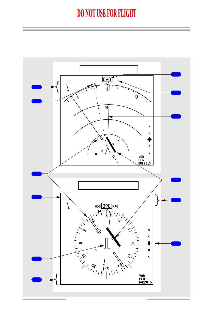
Navigation Displays - Approach Mode
Expanded and Center Approach Modes
[Option - Weather radar range arcs, ADF]
Expanded Approach Mode
7
GS152 TAS160
ILS 1
110.10
HDG
MAG
080 /12
CRS055
DME13.5
1
8
2
9
WX+T
+15
VAR
ADF 1
2
KXYZ
3
10
Center Approach Mode
GS152 TAS160
ILS 1
IALT
4
080 /12
CRS055
11
DME13.5
12
5
ADF 1
2
KXYZ
6
10.11.39
Flight Instruments, Displays -
PFD/ND - Displays
Boeing 737 Operations Manual
1
Wind Direction/Speed/Arrow
2
Selected Heading Bug
3
Selected Course Pointer
4
Groundspeed/True Airspeed
5
Airplane symbol
6
VOR/ADF Selection/Ident or Frequency/VOR DME
[Option - ADF}
7
Current Heading
8
Magnetic/True Reference
9
Track Line
10
Localizer Deviation Indication and Scale
11
Reference ILS Frequency or Ident/Course/DME
12
Glideslope Pointer and Scale
10.11.40
Flight Instruments, Displays -
PFD/ND - Displays
Boeing 737 Operations Manual
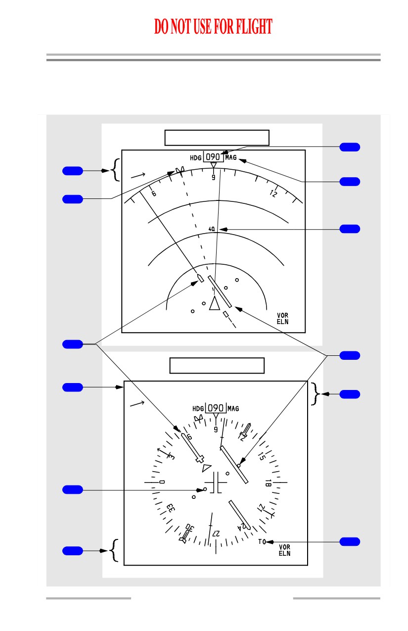
Navigation Displays - VOR Mode
Expanded and Center VOR Modes
[Option - Weather radar range arcs, ADF]
Expanded VOR Mode
7
GS315 TAS312
VOR 2 116.80
350/15
CRS055
1
DME13.5
8
2
9
WX+T
+15
VAR
TO
ADF 1
2
KXYZ
DME13.5
3
10
Centered VOR Mode
4
GS315 TAS312
VOR 1 ELN
350/15
CRS055
11
DME13.5
5
12
ADF 1
2
6
KXYZ
DME13.5
10.11.41
Flight Instruments, Displays -
PFD/ND - Displays
Boeing 737 Operations Manual
1
Wind Direction/Speed/Arrow
2
Selected Heading Bug
3
Selected Course Pointer
4
Groundspeed/True Airspeed
5
Airplane symbol
6
VOR/ADF Selection/Ident or Frequency/VOR DME
[Option - ADF]
7
Current Heading
8
Magnetic/True Reference
9
Track Line
10
Course Deviation Indication and Scale
11
Reference VOR Receiver/Frequency or Ident/Course/DME
12
TO/FROM Indication and TO pointer
10.11.42
Flight Instruments, Displays -
PFD/ND - Displays
Boeing 737 Operations Manual
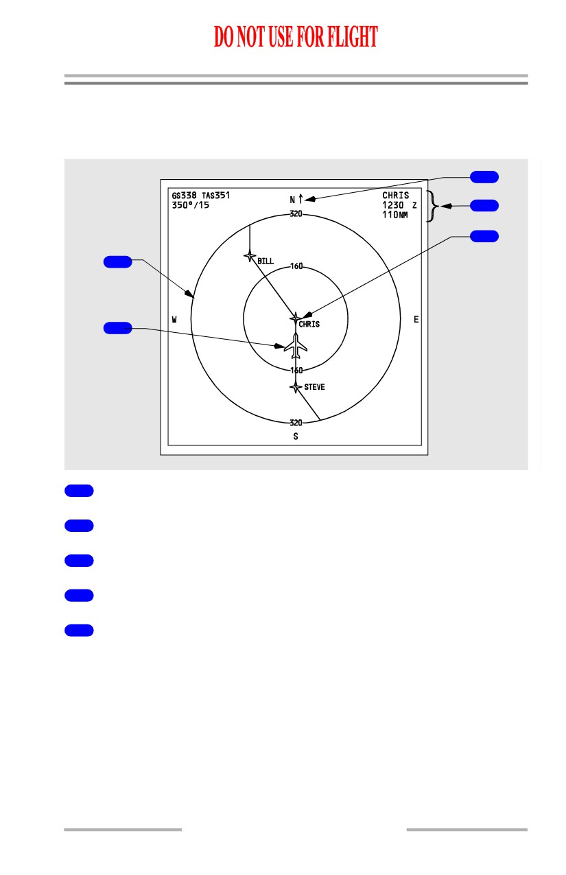
Navigation Displays - Plan Mode
Plan Mode
[Option - Dual FMC]
3
.0
4
5
1
2
FMC L
1
Range Circle
2
Airplane Symbol
3
True North Up Arrow
4
Active Waypoint Information
5
Center Waypoint
The waypoint located at the display center is identified as CTR on the CDU RTE
LEGS page.
10.11.43
Flight Instruments, Displays -
PFD/ND - Displays
Boeing 737 Operations Manual
Navigation Displays - Advisory Messages
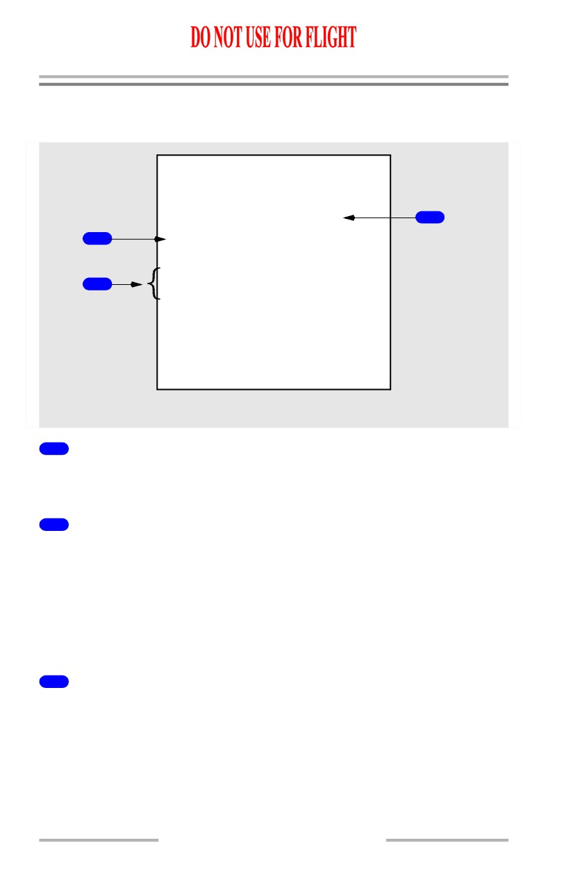
Navigation Advisory Messages
UNABLE REQD NAV PERF-RNP
3
1
EXCESS DATA
MAP RANGE DISAGREE
2
WXR RANGE DISAGREE
MAP/WXR RANGE DISAGREE
1
Excess Data Annunciation (amber)
The amount of map information sent to the primary display system is too great to
display.
2
Range Disagreement Annunciations (amber)
MAP RANGE DISAGREE - Indicates selected range on the EFIS control panel
is different than the MAP display range.
WXR RANGE DISAGREE - Indicates selected range on the EFIS control panel
is different than the WXR display range.
MAP/WXR RANGE DISAGREE - Indicates selected range on the EFIS control
panel is different than the MAP and WXR display ranges.
3
Nav Advisory Message (amber)
UNABLE REQD NAV PERF-RNP - Displayed in MAP or Center MAP during
approach. Refer to Chapter 11 section 60, FMC Messages.
10.11.44
Flight Instruments, Displays -
PFD/ND - Displays
Boeing 737 Operations Manual
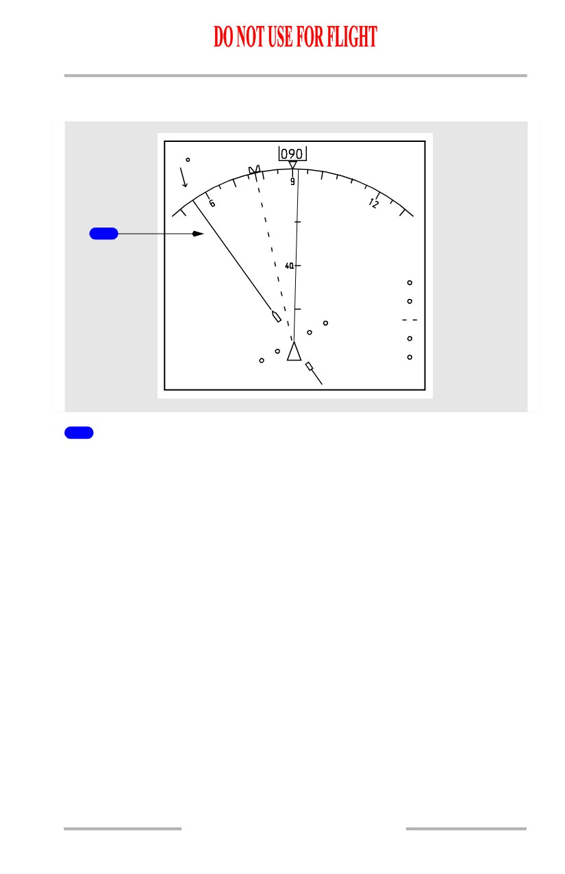
Mode/Frequency Disagree Annunciation
[Option - Track-up display, ADF]
GS152 TAS160
ILS 1 - - - -
TRK
MAG
080 /12
CRS055
- - -
EFIS MODE/NAV FREQ DISAGREE
1
ADF
1
KXYZ
1
EFIS MODE/NAV FREQ DISAGREE (amber)
The ILS or VOR source annunciation corresponds to the position selected on the
EFIS control panel and the tuned VOR/ILS frequency.
The annunciation is displayed:
• if APP is selected with a VOR frequency tuned
• if VOR is selected with an ILS frequency tuned.
The DME display and ILS/VOR frequency at the upper right corner display
dashes.
The localizer deviation bar, VOR course deviation bar and glide slope pointer are
not displayed.
The annunciation is displayed in the expanded APP, center APP, expanded VOR
and center VOR modes.
10.11.45
Flight Instruments, Displays -
PFD/ND - Displays
Boeing 737 Operations Manual
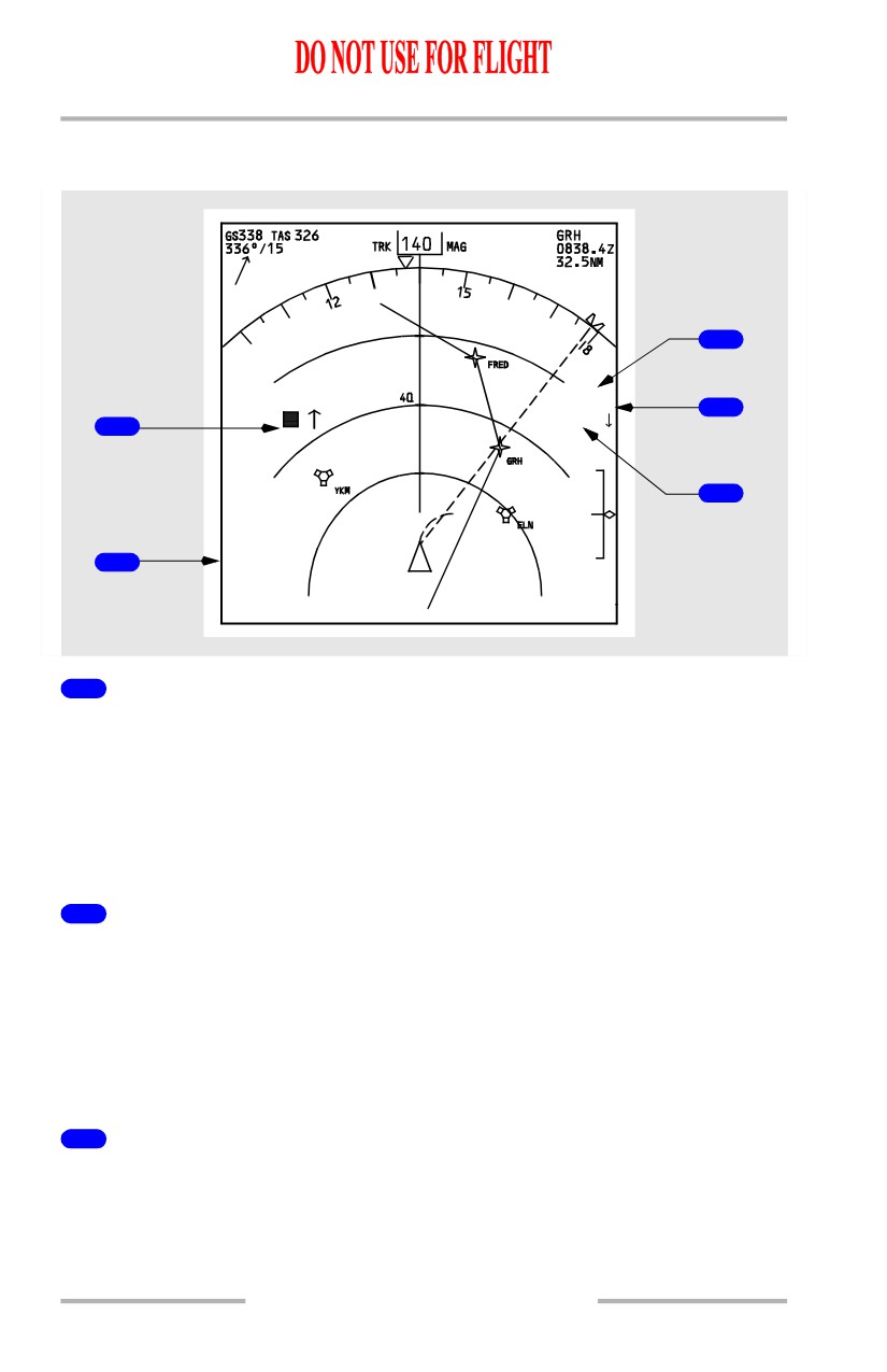
TCAS Messages
[Option - Track-up display, weather radar range arcs, dual FMC]
3
OFFSCALE
TRAFFIC
4
RA 5.3 +03
1
-03
5
2
TFC
FMC L
1
TCAS Traffic Symbols
Note: Refer to section 41 of this chapter for a detailed explanation of the traffic
symbology.
Indicates position of traffic targets.
Displayed in expanded MAP, center MAP, expanded APP and expanded VOR
modes and TFC is selected on the EFIS control panel.
2
TCAS Annunciations
TFC (cyan) - Indicates TFC selected on EFIS control panel in expanded MAP,
center MAP, expanded APP and expanded VOR.
TCAS TEST (cyan) - TCAS in test mode.
TA ONLY (cyan) - TCAS TA mode only.
TCAS OFF (amber) - TCAS off.
3
Offscale (red or amber)
TA (amber) or RA (red) is beyond the selected display range and TFC is selected
on the EFIS control panel.
10.11.46
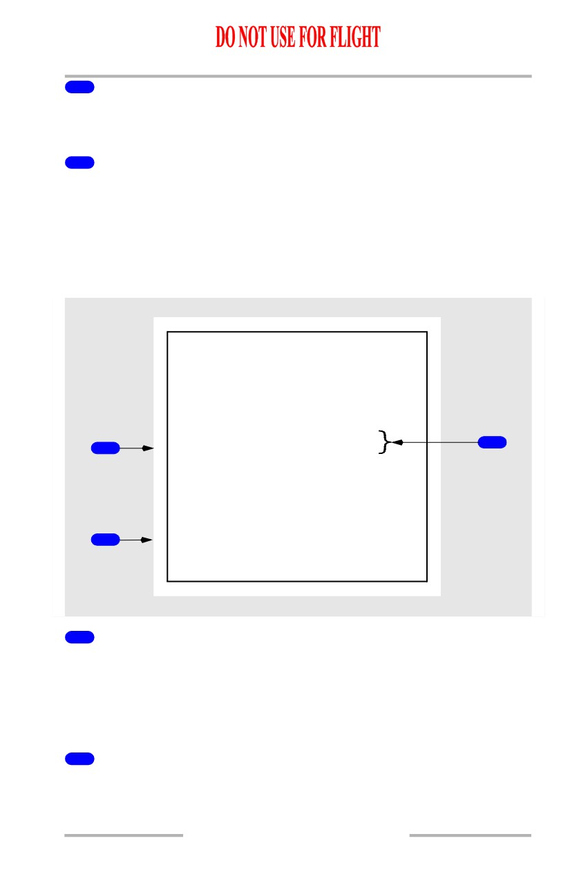
Flight Instruments, Displays -
PFD/ND - Displays
Boeing 737 Operations Manual
4
Traffic (red or amber)
Displayed during a TA (amber) or RA (red) condition whether or not TFC is
selected on the EFIS control panel.
5
No-Bearing Messages (red or amber)
Textual description of TA (amber) or RA (red) traffic with no associated bearing.
Message provides traffic type, range in NM, altitude and a vertical motion arrow.
A maximum of two messages can be displayed simultaneously.
TFC selected on the EFIS control panel.
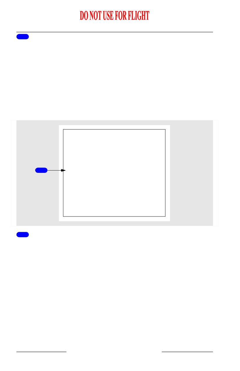
Look-Ahead Terrain Messages (GPWS)
TERR FAIL
TERR RANGE DISAGREE
3
1
TERR POS
MAP/TERR RANGE DISAGREE
TERR INHIBIT
TERR
2
TERR
TEST
1
Terrain Status Annunciation (amber)
TERR FAIL - Look-ahead terrain alerting and display have failed.
TERR POSS - Look-ahead terrain alerting and display unavailable due to position
uncertainty.
TERR INHIBIT - GPWS terrain inhibit switch in TERR INHIBIT position.
2
Terrain Mode Annunciation (cyan)
TERR - Terrain display enabled (manual or automatic display).
TERR TEST - GPWS is operating in self-test mode.
10.11.47
Flight Instruments, Displays -
PFD/ND - Displays
Boeing 737 Operations Manual
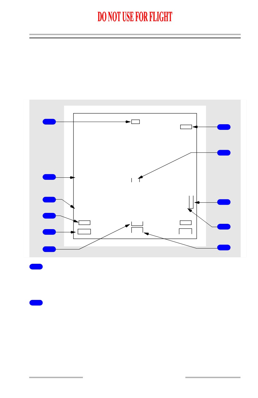
3
Terrain Range Status Annunciation (amber)
TERR RANGE DISAGREE -
• terrain display enabled, and
• terrain output range disagrees with selected EFIS control panel range.
MAP/TERR RANGE DISAGREE -
• terrain display enabled, and
• terrain output range disagrees with selected EFIS control panel range, and
• map display output range disagrees with selected EFIS control panel
range.
Predictive Windshear System (PWS) Message
1
PWS FAIL
1
PWS FAIL Annunciation (amber)
Predictive windshear alerting and display have failed.
10.11.48
Flight Instruments, Displays -
PFD/ND - Displays
Boeing 737 Operations Manual
Navigation Displays - Failure Indications and Flags
Dashes replace numbers if there is no computed information. Failure flags replace
symbols or failure messages are displayed, as appropriate.
Expanded MAP, Center MAP, Expanded APP, Expanded VOR
Modes
[Option - Track-up display, dual ADF]
TRK
1
HDG
DME
1
7
DME
2
8
2
WXR
FAIL
MAP
G
V
3
/
T
9
TCAS
S
K
FAIL
VOR1
4
ADF1
VOR
2
ADF2
VOR1
VOR2
10
LOC
5
DME
1
DME2
6
11
1
Track Failure Flag (expanded and center MAP modes)
[Option - Track-up display]
Track or heading display has failed.
2
Weather Radar Annunciations (expanded and center MAP, expanded
APP, expanded VOR modes)
WXR FAIL - Weather radar has failed. No weather data are displayed.
WXR WEAK - Weather radar calibration fault.
WXR ATT - Attitude stabilization for antenna has been lost.
WXR STAB - Antenna stabilization is off.
WXR DSP - Range data input has failed. Only displayed in WXR TEST
10.11.49
Flight Instruments, Displays -
PFD/ND - Displays
Boeing 737 Operations Manual
3
TCAS Failure Flag (expanded and center MAP, expanded VOR,
expanded APP, PLAN modes)
TCAS has failed.
4
ADF 1 and ADF 2 or VOR 1 and VOR 2 Failure Flag (expanded and
center MAP, expanded APP, expanded VOR modes)
[Option - Dual ADF]
ADF or VOR display has failed.
5
DME 1 and DME 2 Failure Flag (expanded and center MAP,
expanded APP, expanded VOR modes)
Selected VOR DME display has failed.
6
VOR 1, 2 Failure Flag (expanded VOR mode)
VOR display has failed.
7
Reference VOR DME (expanded VOR mode) and Reference ILS
DME (expanded APP mode)
Reference VOR or ILS DME display has failed.
8
MAP Failure Flag (expanded and center MAP, PLAN modes)
The related FMC generated map display has failed.
9
Vertical Track Failure Flag (expanded and center MAP modes)
FMC vertical track data are invalid.
10
ILS Glideslope Failure Flag (expanded APP mode)
ILS glideslope display has failed.
11
ILS Localizer Failure Flag (expanded APP mode)
ILS localizer display has failed.
10.11.50
Flight Instruments, Displays -
PFD/ND - Displays
Boeing 737 Operations Manual
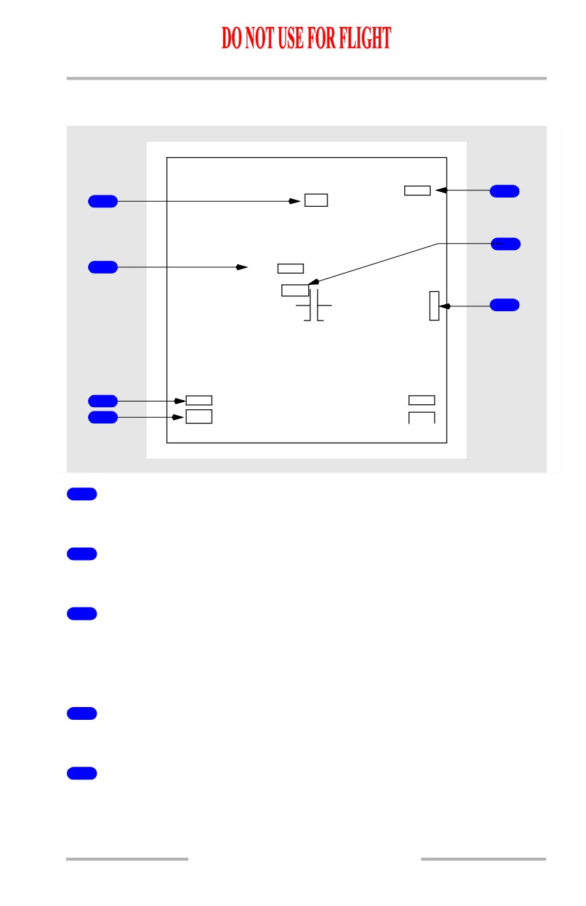
ND Failure Flags - Center APP and Center VOR Modes
[Option - Dual ADF]
DME
1
5
DME
2
1
HDG
6
VOR
1
2
VOR
2
LOC
G
/
7
S
TCAS
FAIL
ADF1
ADF2
3
VOR1
VOR
2
4
DME
1
DME2
1
Heading Failure Flag (center APP, center VOR modes)
Heading display has failed.
2
VOR Failure Flag (center VOR mode)
VOR display has failed.
3
ADF 1 and ADF 2 or VOR 1 and VOR 2 Failure Flag (center APP,
center VOR modes)
[Option - Dual ADF]
VOR or ADF display has failed.
4
DME 1 and DME 2 Failure Flag (center APP, center VOR modes)
Selected VOR DME display has failed.
5
Reference VOR DME (center VOR mode) and Reference ILS DME
(center APP mode)
Reference VOR or ILS DME display has failed.
10.11.51
Flight Instruments, Displays -
PFD/ND - Displays
Boeing 737 Operations Manual
6
ILS Localizer Failure Flag (center APP mode)
ILS localizer display has failed.
7
ILS Glideslope Failure Flag (center APP mode)
ILS glide slope display has failed.
10.11.52
Boeing 737 Operations Manual
Flight Instruments, Displays
Chapter 10
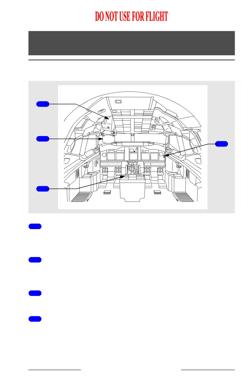
Head-Up Display System - Displays
Section 12
System Components
[Option - Model 2350 with 3-light first officer panel]
1
2
4
3
1
Overhead Unit
Contains the CRT and projection optics to display the symbolic image on the
combiner.
2
Combiner
Combines displayed flight symbology with the pilot’s view through window
No. 1.
3
Control Panel
Used for data entry and to select modes of operation.
4
Annunciator
Provides system status and warning annunciations during a CAT III approach.
10.12.1
Flight Instruments, Displays -
Head-Up Display System -
Displays
Boeing 737 Operations Manual
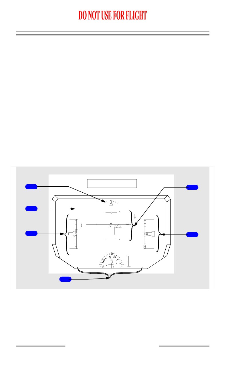
Combiner Display
The combiner displays symbology and fault indications for the HUD system.
Display modes of operation include:
• Primary (PRI)
• AIII approach
• Instrument Meteorological Conditions (IMC) approach
• Visual Meteorological Conditions (VMC) approach
Typical display modes are shown below.
Note: Not all symbols are represented in this section. Refer to Section 10-42,
Head-Up Display System, Symbology, for a complete listing of HUD
system symbology.
Primary (PRI) Mode Display
[Option - Model 2350]
The primary mode can be used for all phases of flight from takeoff to landing
including low visibility takeoff operations.
PRI (in flight) Mode
1
5
FMC SPD
LNAV
H 310
VNAV SPD
FD
2
5
5
213
3600
240
30
31
28
4400
220
4200
80
3
2
0
3
40
60
40
6
-5
-5
3800
180
3600
GS
185
DME
31.2
-200
VS
HDG
318
CRS
300
24.6NM
VOR1
FMC L
460
4
10.12.2
Flight Instruments, Displays -
Head-Up Display System -
Displays
Boeing 737 Operations Manual
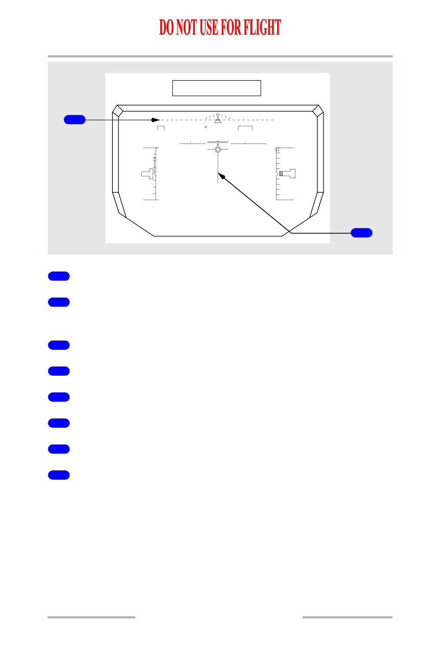
PRI (ground) Mode
7
N1
H 310
TO/GA
FD
31
150
6000
V1
140
400
90
200
70
00002
50
-200
-400
GS
35
HDG
310
CRS
310
ILS1
8
1
Bank Scale and Pointer
2
Flight Mode Annunciations (FMAs)
Refer to Chapter 4, Automatic Flight.
3
Airspeed Indications
4
Navigation Indications
5
Attitude Indications
6
Altitude Indications
7
TO/GA Pitch Target Line
8
Ground Localizer Line
10.12.3