Boeing 737 - 600/700/800/900. Operations Manual (1997 year) - page 21
Performance Dispatch
Landing
FAA
Category G Brakes
Boeing 737 Operations Manual
Landing
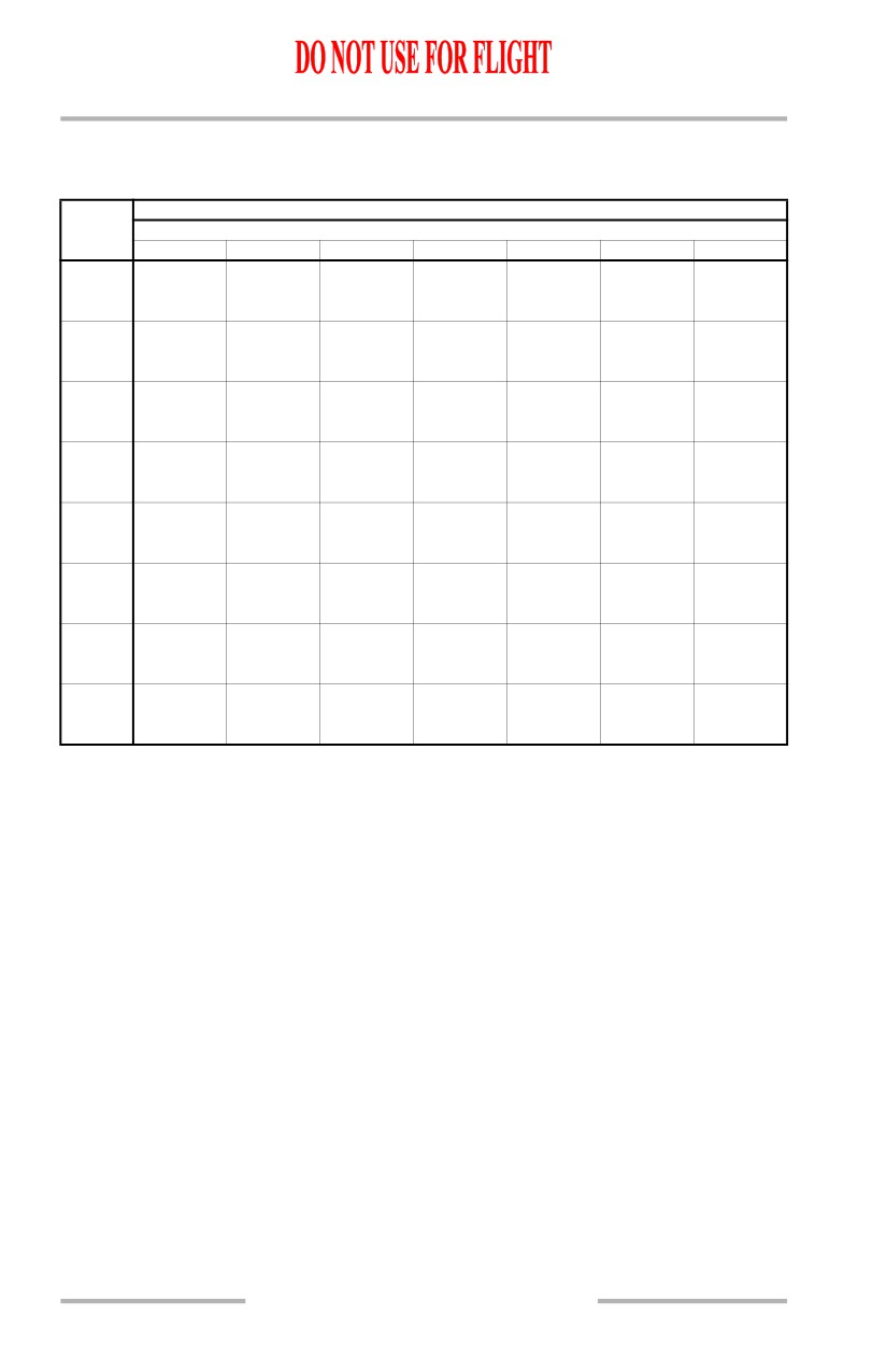
Landing Climb Limit Weight
Valid for approach with flaps 15 and landing with flaps 30 or 40
Based on engine bleed for packs on and anti-ice off
LANDING CLIMB LIMIT WEIGHT (1000 LB)
AIRPORT
AIRPORT PRESSURE ALTITUDE (FT)
OAT (°C)
-2000
0
2000
4000
6000
8000
10000
54
150.1
140.6
52
152.8
144.3
50
155.5
148.6
136.4
48
158.4
151.4
140.0
46
161.4
154.2
143.5
132.1
44
164.3
156.8
146.5
135.3
42
167.0
159.5
149.2
138.6
127.1
40
169.8
162.3
151.8
141.0
130.0
38
172.6
165.1
154.5
143.5
132.9
121.0
36
175.4
168.0
157.1
146.6
135.3
123.1
34
178.0
170.9
160.1
149.5
137.7
125.2
115.0
32
178.2
174.0
162.8
151.9
139.8
127.6
117.4
30
178.4
176.9
165.2
153.7
141.9
129.8
119.6
28
178.6
177.1
167.2
155.5
143.9
131.8
121.5
26
178.8
177.3
169.3
157.0
145.3
133.8
123.4
24
178.9
177.4
169.4
158.3
146.6
135.5
124.8
22
179.1
177.6
169.5
159.4
147.8
136.5
125.9
20
179.2
177.7
169.6
159.5
148.9
137.4
127.0
18
179.4
177.8
169.7
159.6
149.9
138.2
127.8
16
179.5
178.0
169.8
159.7
150.0
139.0
128.6
14
179.7
178.1
169.9
159.7
150.1
139.8
129.3
12
179.8
178.2
170.0
159.8
150.1
139.8
130.1
10
180.0
178.4
170.1
159.9
150.2
139.9
130.8
-40
181.4
179.6
171.2
161.0
151.2
140.8
132.1
With engine bleed for packs off, increase weight by 2700 lb.
With engine anti-ice on, decrease weight by 500 lb.
With engine and wing anti-ice on, decrease weight by 3000 lb.
When operating in icing conditions during any part of the flight with forecast landing temperature below
10°C, decrease weight by 12100 lb.
Includes brake energy limits.
PD.42.2
Performance Dispatch
FAA
Landing
Category G Brakes
Boeing 737 Operations Manual
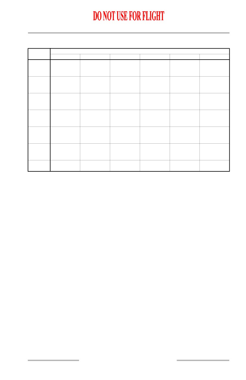
Quick Turnaround Limit Weight
Flaps 40
AIRPORT
PRESSURE ALTITUDE (FT)
OAT (°C)
0
2000
4000
6000
8000
10000
54
176.6
50
177.7
171.2
45
179.2
172.6
166.1
40
180.7
174.1
167.5
161.1
35
182.3
175.6
168.9
162.5
156.2
30
183.8
177.1
170.4
163.9
157.5
151.3
25
185.4
178.6
171.8
165.3
158.9
152.6
20
187.1
180.2
173.3
166.8
160.3
154.0
15
188.9
181.8
174.9
168.3
161.7
155.4
10
190.0
183.4
176.5
169.8
163.2
156.8
5
190.0
185.1
178.2
171.4
164.7
158.2
0
190.0
186.9
179.8
173.0
166.3
159.8
-5
190.0
188.8
181.6
174.7
167.9
161.3
-10
190.0
190.0
183.3
176.4
169.6
162.9
-15
190.0
190.0
185.2
178.2
171.3
164.5
-20
190.0
190.0
187.1
180.0
173.0
166.2
-30
190.0
190.0
190.0
183.8
176.7
169.7
-40
190.0
190.0
190.0
187.9
180.6
173.5
-50
190.0
190.0
190.0
190.0
184.7
177.4
-54
190.0
190.0
190.0
190.0
186.4
179.1
Increase weight by 1500 lb per 1% uphill slope. Decrease weight by 3100 lb per 1% downhill slope.
Increase weight by 4000 lb per 10 knots headwind. Decrease weight by 16600 lb per 10 knots tailwind.
After landing at weights exceeding those shown above, adjusted for slope and wind, wait at least 67 minutes
and check that wheel thermal plugs have not melted before executing a takeoff.
As an alternate procedure, ensure that each brake pressure plate temperature, without artificial cooling, is
less than 218°C as follows: No sooner than 10 and no later than 15 minutes after parking, measure each brake
pressure plate surface temperature at a minimum of two points per brake by an accurate method (using a
Doric Microtemp 450 hand held thermometer or equivalent, hold temperature probe in place for 20 seconds
or until reading stabilizes). If each measured temperature is less than 218°C, immediate dispatch is allowed;
otherwise the required minimum ground wait period of 67 minutes applies.
PD.42.3
Performance Dispatch
Landing
FAA
Category G Brakes
Boeing 737 Operations Manual
Intentionally
Blank
PD.42.4
FAA
Category G Brakes
Boeing 737 Operations Manual
Performance Dispatch
Chapter PD
Text
Section 43
Text
Introduction
This chapter contains self dispatch performance data intended primarily
for use by flight crews in the event that information cannot be obtained
from the airline dispatch office. The takeoff data provided is for a single
takeoff flap at max takeoff thrust. The range of conditions covered is
limited to those normally encountered in airline operation. In the event of
conflict between the data presented in this chapter and that contained in the
approved Airplane Flight Manual, the Flight Manual shall always take
precedence.
Takeoff
The maximum allowable takeoff weight will be the least of the Field,
Climb, Obstacle, Brake Energy and Tire Speed Limit Weights as
determined from the tables shown.
Field Limit Weight - Slope and Wind Corrections
These tables for dry and wet runways provide corrections to the field
length available for the effects of runway slope and wind component along
the runway. Enter the appropriate table with the available field length and
runway slope to determine the slope corrected field length. Next enter the
appropriate table with slope corrected field length and wind component to
determine the slope and wind corrected field length.
Field and Climb Limit Weight
Tables are presented for selected airport pressure altitudes and runway
conditions and show both Field and Climb Limit Weights. Enter the
appropriate table for pressure altitude and runway condition with “Slope
and Wind Corrected Field Length” determined above and airport OAT to
obtain Field Limit Weight. Also read Climb Limit Weight for the same
OAT. Intermediate altitudes may be interpolated or use next higher
altitude. When finding a maximum weight for a wet runway, the dry
runway limit weight must also be determined and the lower of the two
weights used.
Obstacle Limit Weight
The Reference Obstacle Limit Weight table provides obstacle limit
weights for reference airport conditions based on obstacle height above the
runway surface and distance from brake release. Enter the adjustment
PD.43.1
Performance Dispatch
Text
FAA
Category G Brakes
Boeing 737 Operations Manual
tables to adjust the reference Obstacle Limit Weight for the effects of
OAT, pressure altitude and wind as indicated. In the case of multiple
obstacles, enter the tables successively with each obstacle and determine
the most limiting weight.
Tire Speed Limit
Maximum tire speed limited weights are presented for 225 MPH tires. To
determine the tire speed limit weight, enter the table with OAT and airport
pressure altitude. Adjust the tire speed limit weight according to the notes
below the table to account for wind.
Enroute
Long Range Cruise Maximum Operating Altitude
These tables provide the maximum operating altitude in the same manner
as the FMC. Maximum altitudes are shown for a given cruise weight and
maneuver capability. Note that this table considers both thrust and buffet
limits, providing the more limiting of the two. Any data that is thrust
limited is denoted by an asterisk and represents only a thrust limited
condition in level flight with 100 ft/min residual rate of climb. Flying
above these altitudes with sustained banks in excess of approximately 15°
may cause the airplane to lose speed and/or altitude. The altitudes shown
in the table are limited to the maximum certified altitude of 41000 ft.
Long Range Cruise Trip Fuel and Time
Long Range Cruise Trip Fuel and Time tables are provided to determine
trip time and fuel required to destination.
To determine trip fuel and time for a constant altitude cruise, first enter the
Ground to Air Miles Conversion table to convert ground distance and
enroute wind to an equivalent still air distance for use with the Reference
Fuel and Time tables. Next, enter the Reference Fuel and Time table with
air distance from the Ground to Air Miles Conversion table and the desired
altitude and read Reference Fuel and Time Required. Lastly, enter the Fuel
Required Adjustment table with the Reference Fuel and the planned
landing weight to obtain the adjustment to the fuel required at the planned
landing weight.
Long Range Cruise Step Climb Trip Fuel and Time
The Long Range Cruise Step Climb Trip Fuel and Time tables are provided
to determine trip time and fuel required to destination when flying a step
climb profile. Step climb profiles are based on 4000 ft step climbs to keep
the flight within 2000 ft of the optimum altitude for the current cruise
PD.43.2
Performance Dispatch
FAA
Text
Category G Brakes
Boeing 737 Operations Manual
weight. To determine trip fuel and time, enter the Ground to Air Miles
Conversion table and determine air distance as discussed above. Then
enter the Trip Fuel and Time Required table with air distance and planned
landing weight to read trip fuel. Continue across the table to read trip time.
Short Trip Fuel and Time
These tables are provided to determine trip fuel and time for short
distances or alternates. Obtain air distance from the table using the ground
distance and wind component to the alternate. Enter the Trip Fuel and Time
Required table with air distance and read trip fuel required for the expected
landing weight, together with time to alternate at right. For distances
greater than shown or other altitudes, use the Long Range Cruise Trip Fuel
and Time tables.
Holding Planning
This table provides total fuel flow information necessary for planning flaps
up holding and reserve fuel requirements. Data is based on the FMC
holding speed schedule which is the higher of the maximum endurance and
flaps up maneuver speeds. As noted, the fuel flow is based on flight in a
racetrack holding pattern. For holding in straight and level flight, reduce
table values by 5%.
Crew Oxygen Requirements
Tables are provided to determine the minimum dispatch oxygen pressure
for protective breathing equipment used by the flight crew. Enter the
number of crew plus observers using oxygen and read the minimum
cylinder pressure required for the appropriate bottle temperature and size.
These pressures provide sufficient oxygen for 15 minutes of protective
breathing for each flight crew member plus 10% contingency at 8000 ft
cabin pressure altitude. Route specific analysis is necessary to determine
if additional oxygen pressure is needed to meet supplemental oxygen
requirements.
Net Level Off Weight
The Net Level Off Weight table is provided to determine terrain clearance
capability in straight and level flight following an engine failure.
Regulations require terrain clearance planning based on net performance
which is the gross (or actual) gradient performance degraded by 1.1%. In
addition, the net level off pressure altitude must clear the terrain by
1000 ft.
PD.43.3
Performance Dispatch
Text
FAA
Category G Brakes
Boeing 737 Operations Manual
To determine the maximum weight for terrain clearance, enter the table
with required net level off pressure altitude and expected ISA deviation to
obtain weight. Adjust weight for anti-ice operation as noted below the
table.
Extended Range Operations
Regulations require that flights conducted over a route that contains a
point further than one hour’s time at
“normal one engine inoperative
speed” from an adequate diversion airport comply with rules set up
specifically for “Extended Range Operation with Two Engine airplanes.”
This section provides reserve fuel planning information for the "Critical
Fuel Scenario" based on two engine operation at Long Range Cruise as
well as single engine operation at Long Range Cruise.
Long Range Cruise Critical Fuel Reserves
Enter the Ground to Air Miles Conversion table with forecast wind and
ground distance to diversion airport from critical point to obtain air
distance. Now enter the Critical Fuel table with air distance and expected
weight at the critical point and read required fuel. Apply the noted fuel
adjustments as necessary. Regulations require a
5% allowance for
performance deterioration unless a value has been established by the
operator for inservice deterioration.
As noted below each table, the fuel required is the greater of the two engine
fuel and the single engine fuel. This fuel is compared to the amount of fuel
normally onboard the airplane at that point in the route. If the fuel required
by the critical fuel reserves exceeds the amount of fuel normally expected,
the fuel load must be adjusted accordingly.
Landing
Tables are provided for determining the maximum landing weight as
limited by field length or climb requirements for a single landing flap.
Maximum landing weight is the lowest of the field length limit weight,
climb limit weight, or maximum certified landing weight.
Landing Field Limit Weight
Obtain wind corrected field length by entering the Wind Corrected Field
Length table with field length available and wind component along the
runway. Now enter the Field Limit Weight table with wind corrected field
length and pressure altitude to read field limit weight for the expected
runway condition.
PD.43.4
Performance Dispatch
FAA
Text
Category G Brakes
Boeing 737 Operations Manual
Landing Climb Limit Weight
Enter the table with airport OAT and pressure altitude to read landing
climb limit weight. Apply the noted adjustments as required.
Quick Turnaround Limit Weight
Enter the table with airport pressure altitude and OAT to read maximum
quick turnaround weight. Apply the noted adjustments as required.
If the landing weight exceeds the maximum quick turnaround weight, wait
the specified time and then check that the wheel thermal plugs have not
melted before executing a subsequent takeoff, or ensure the brake
temperature is within limits using the alternate procedure described on the
page.
PD.43.5
Performance Dispatch
Text
FAA
Category G Brakes
Boeing 737 Operations Manual
Intentionally
Blank
PD.43.6
Boeing 737 Operations Manual
General Information
Chapter 1
Table of Contents
Section 0
1.0 General Information-Table of Contents
Dimensions
1.10.1
Principal Dimensions
1.10.1
Instrument Panels
1.20.1
Panel Arrangement
1.20.1
Aft Flight Deck Overview
1.20.2
Left Forward Panel
1.20.3
Right Forward Panel
1.20.4
Glareshield Panel
1.20.5
Center Forward Panel
1.20.7
Forward Aisle Stand
1.20.10
737-600/700 Forward Overhead Panel
1.20.11
737-800/900 Forward Overhead Panel
1.20.12
Aft Overhead Panel
1.20.13
Control Stand
1.20.14
Aft Electronic Panel
1.20.15
Auxiliary Panels
1.20.17
Attendant Panels
1.20.18
Attendant Handset
1.20.19
Controls and Indicators
1.30.1
Flight Deck Lighting
1.30.1
Map and Chart Light Controls
1.30.1
Main Panel Lighting
1.30.1
Background and AFDS Flood Light Control
1.30.2
Flood and Aft Electronics Lights Controls
1.30.2
Overhead/Circuit Breaker Panel Light Controls
1.30.3
Dome Light Control
1.30.3
Master Lights Test and Dim Switch
1.30.4
1.TOC.0.1
General Information -
Table of Contents
Boeing 737 Operations Manual
Exterior Lighting
1.30.5
Landing, Runway Turnoff and Taxi Lights
1.30.5
Miscellaneous Exterior Lights
1.30.6
Emergency Lighting and Passenger Signs
1.30.7
Doors
1.30.8
Cabin Door
1.30.8
Flight Deck Security Door
1.30.9
Exterior Door Annunciator Lights
1.30.12
Passenger Entry/Galley Service Doors
1.30.16
Oxygen
1.30.16
Oxygen Panel
1.30.16
Oxygen Mask Panel
1.30.17
Oxygen Mask and Regulator
1.30.18
Forward Airstairs
1.30.19
Interior and Exterior Controls
1.30.19
Water System Controls
1.30.21
Lavatory Controls
1.30.22
Systems Description
1.40.1
Introduction
1.40.1
Lighting Systems
1.40.1
Exterior Lighting
1.40.1
Exterior Lighting Locations
1.40.3
Flight Deck Lighting
1.40.4
Passenger Cabin Lighting
1.40.4
Passenger Cabin Signs
1.40.5
Emergency Lighting
1.40.5
Emergency Exit Lighting
1.40.9
Oxygen Systems
1.40.10
Oxygen System Schematic
1.40.11
Flight Crew Oxygen System
1.40.12
Portable Protective Breathing Equipment
1.40.13
Passenger Oxygen System
1.40.13
1.TOC.0.2
General Information -
Table of Contents
Boeing 737 Operations Manual
PSU Oxygen Mask Compartment
1.40.14
Passenger Portable Oxygen
1.40.15
Passenger Portable Oxygen Schematic
1.40.15
Fire Extinguishers
1.40.16
Water Fire Extinguishers
1.40.16
Halon (BCF) Fire Extinguishers
1.40.16
Fire Extinguisher Usage
1.40.18
Emergency Equipment Symbols
1.40.19
Emergency Equipment Locations
1.40.20
Doors and Windows
1.40.22
Cabin Door
1.40.22
Flight Deck Security Door
1.40.23
Flight Deck Number Two Windows
1.40.24
Lower Cargo Compartments
1.40.25
Emergency Escape
1.40.25
Emergency Evacuation Routes
1.40.26
Flight Deck Window Emergency Egress
1.40.27
Escape Slide Detachment Handle
1.40.29
Escape Straps
1.40.30
Emergency Exit Doors
1.40.33
Pilot Seat Adjustment
1.40.36
Pilot Seat Adjustment
1.40.36
Galleys
1.40.36
Electrical Power
1.40.37
Water Service
1.40.37
Water System
1.40.37
Quantity Indication and System Operation
1.40.38
Hot Water
1.40.38
Servicing
1.40.38
Forward Airstair
1.40.38
Interior Control
1.40.39
Exterior Control
1.40.39
Airstairs
1.40.40
1.TOC.0.3
General Information -
Table of Contents
Boeing 737 Operations Manual
Intentionally
Blank
1.TOC.0.4
Boeing 737 Operations Manual
Airplane General, Emergency
Chapter 1
Equipment, Doors, Windows
Dimensions
Section 10
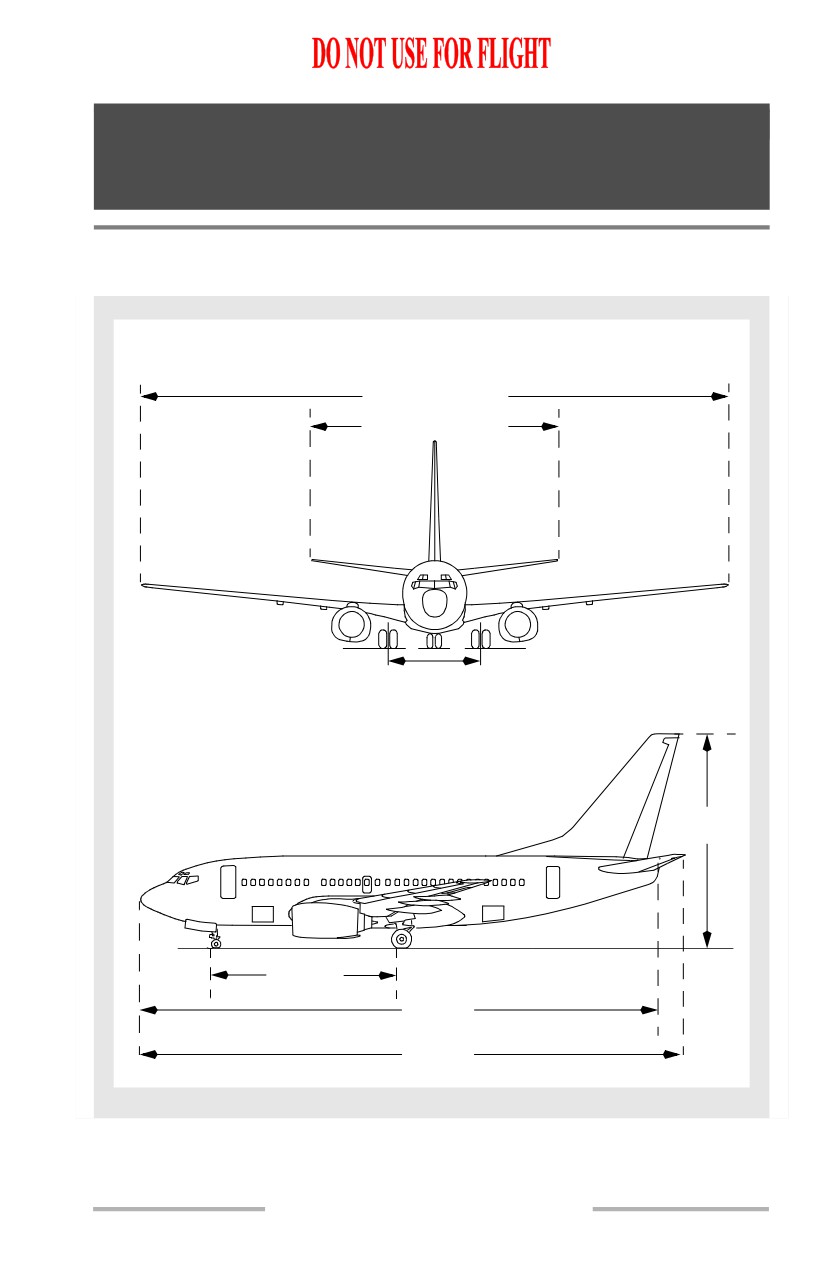
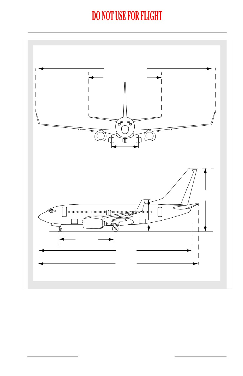
Principal Dimensions
[Option: 737-600]
112'-7" (34.40m)
47'-2" (14.30m)
18'-8"
(5.70m)
41'-2"
(12.50m)
36'-9"
(11.20m)
97'-9"
(29.80m)
102'-6"
(31.20m)
1.10.1
Airplane General, Emergency
Equipment, Doors, Windows -
Dimensions
Boeing 737 Operations Manual
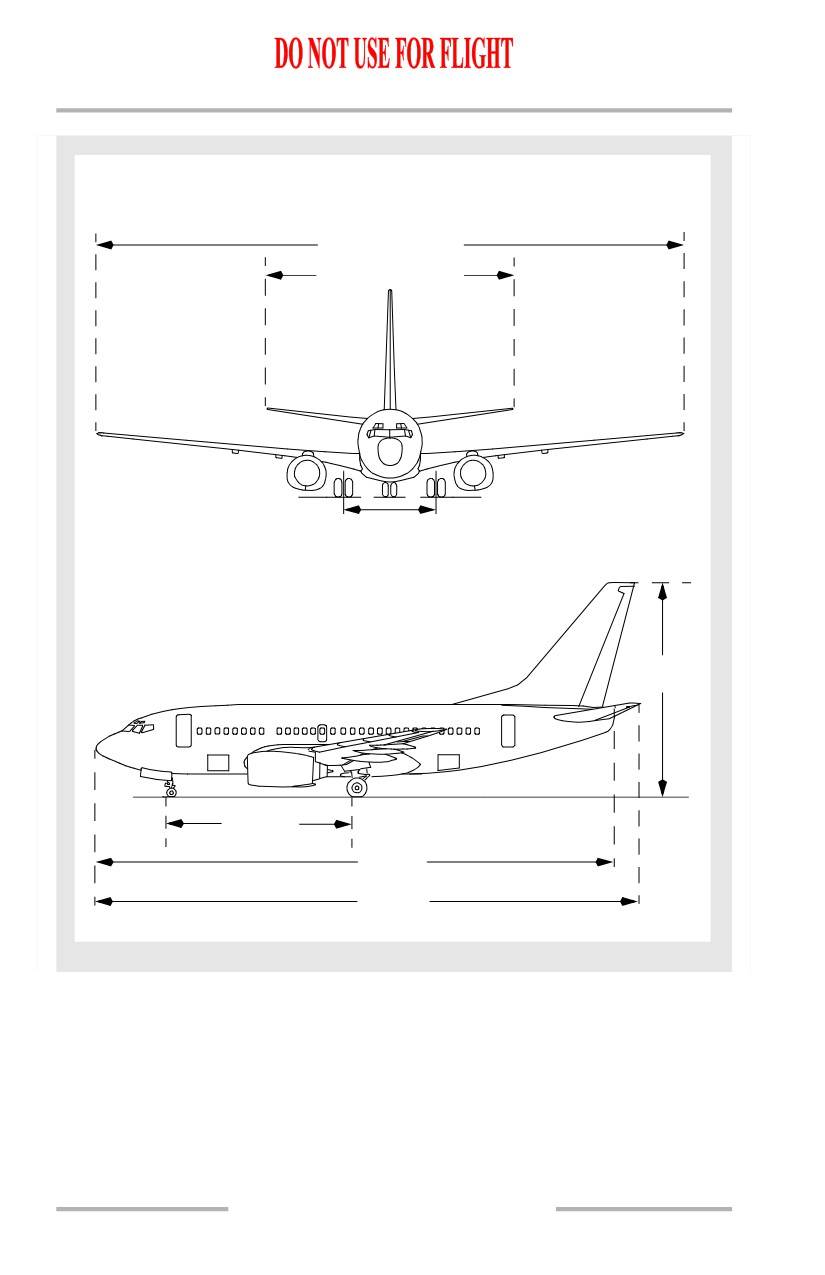
[Option: 737-700]
112'-7" (34.40m)
47'-2" (14.30m)
18'-8"
(5.70m)
41'-2"
(12.50m)
41'-3"
(12.60m)
106'-7"
(32.50m)
110'-4"
(33.60m)
1.10.2
Airplane General, Emergency
Equipment, Doors, Windows -
Dimensions
Boeing 737 Operations Manual
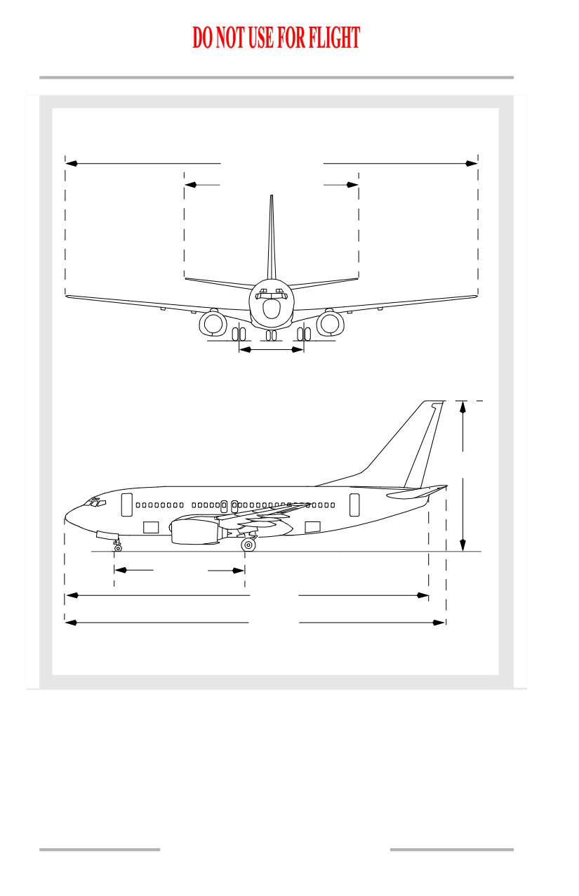
[Option: 737-800 with Blended Winglets]
117'-5" (35.79m)
47'-2" (14.30m)
18'-8"
(5.70m)
41'-2"
(12.50m)
20'-4"(6.20m)
51'-1"
(15.60m)
124'-9"
(38.00m)
129'-6"
(39.50m)
1.10.3
Airplane General, Emergency
Equipment, Doors, Windows -
Dimensions
Boeing 737 Operations Manual
[Option: 737-900]
112'-7" (34.40m)
47'-2" (14.30m)
18'-8"
(5.70m)
41'-2"
(12.50m)
56'-4"
(17.20m)
133'-5"
(40.70m)
138'-2"
(42.10m)
1.10.4
Boeing 737 Operations Manual
Airplane General, Emergency
Chapter 1
Equipment, Doors, Windows
Instrument Panels
Section 20
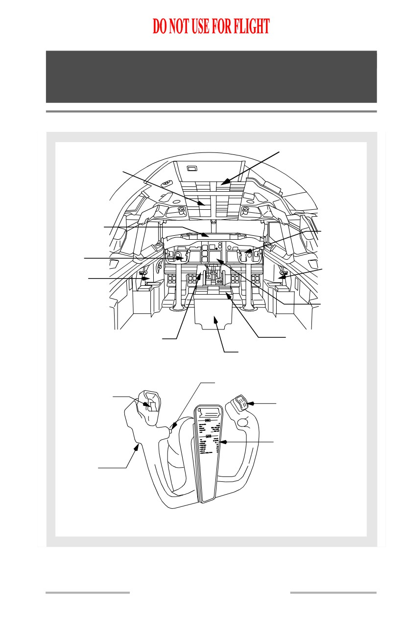
Panel Arrangement
AFT OVERHEAD PANEL
FORWARD
OVERHEAD
PANEL
GLARESHIELD
PANEL
RIGHT
FORWARD
PANEL
LEFT
FORWARD
PANEL
FIRST
OFFICER
CAPTAIN
SIDE
SIDE
PANEL
PANEL
CENTER
INSTRUMENT
PANEL
FORWARD ELECTRONIC PANEL
AFT ELECTRONIC PANEL
CONTROL STAND
AUTOPILOT DISENGAGE SWITCH
STABILIZER
TRIM SWITCH
MEMORY DEVICE
WRITING PAD HOLDER
CLIP WITH CHECKLIST
PUSH-TO-TALK
SWITCH
CAPTAIN CONTROL WHEEL DETAIL
1.20.1
Airplane General, Emergency
Equipment, Doors, Windows -
Instrument Panels
Boeing 737 Operations Manual
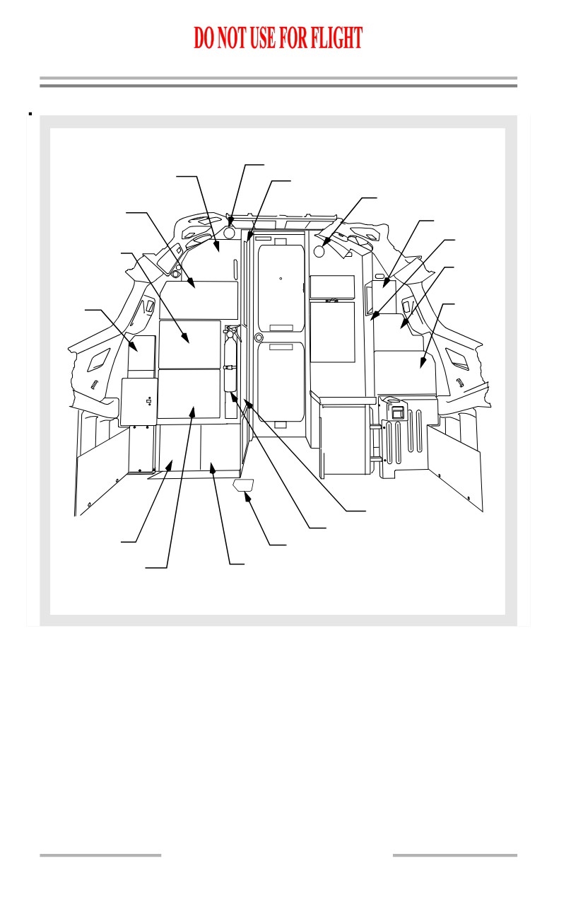
Aft Flight Deck Overview
P6-1 NAV,
WHITE DOME LIGHT
INST, & COMM
OBSERVER OXYGEN MASK
WHITE DOME LIGHT
P6-2
SYSTEMS
P18-1 NAV
P6-3
FUEL SYSTEM,
COAT
LIGHTING &
STOWAGE
LANDING GEAR
P18-2
INST
STBY
& COMM
POWER
CONTROL
P18-3
UNIT
ANTI-ICE
LIGHTING
OBSERVERS SEAT
FIRE EXTINGUISHER
P6-12
WINDOW HEAT
MANUAL GEAR RELEASE
P6-4 AIR COND
P6-11 WINDOW HEAT
& ELECTRICAL
AFT FLIGHT DECK OVERVIEW
1.20.2
Airplane General, Emergency
Equipment, Doors, Windows -
Instrument Panels
Boeing 737 Operations Manual
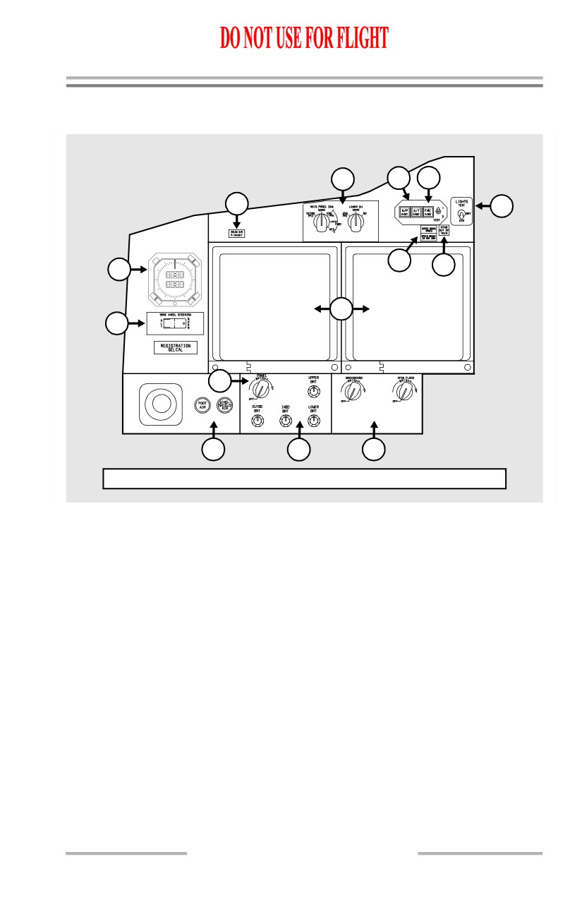
Left Forward Panel
[Option - Typical]
10
4
11
15
1
CHR
TIME/DATE
MANUTC
9
60
SET
4
10
50
TIME
10
DAY MOYR
40
20
ET
RUN
ET CHR
HLD
30
RESET
10
14
1
3
10
1
Circled numbers refer to chapters where information on the item may be found
1.20.3