Seat Toledo. Service Manual - part 6
-------------------------------------------------------------------------------------------------------------------------------------------------------------
Fuses and bulbs
Dipped beam headlights
Turn signal lights
Daylight
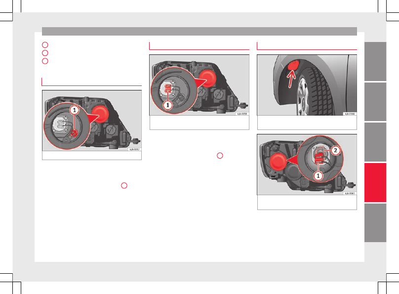
Changing side light bulbs
Fig. 89
Changing side light bulbs.
–
Raise the bonnet.
–
Remove the protective cover
.
–
Remove the bulb holder
›››
1
by
pulling it outwards.
–
Remove the bulb by pulling it out and fit
the new one.
–
Installation involves all of the above steps
in reverse sequence.
–
Fit the protective cover. Make sure that the
cover fits correctly on the housing during
operation.
–
Check whether the new bulb is working.
C
D
E
Changing main beam headlight bulb
Fig. 90
Changing main beam headlight
bulbs.
–
Raise the bonnet.
–
Remove the protective cover.
–
Remove connector
›››
1
by pulling
outward.
–
Extract the bulb and fit the replacement so
that it fits correctly into the recess on the
reflector.
–
Installation involves all of the above steps
in reverse sequence.
–
Fit the protective cover. Make sure that the
cover fits correctly on the housing during
operation.
–
Check whether the new bulb is working.
Changing dipped beam light bulbs
Fig. 91
Changing dipped beam headlight
bulbs: wheel housing.
Fig. 92
Changing dipped beam headlight
bulbs.
–
Turn the wheel for access to the wheel
housing cover and remove the cover
–
Remove the protective cover from the head-
light
.
»
85