Haima M3. Service Manual - part 5
Electronic Fuel Injection Control System 1B
-
16
multimeter, and analogue multimeter shall not be
used to inspect the electronic fuel injection
system’s lines.
3. In the case of overhauling the vehicle with
anti-theft system, if the ECU will be replaced,
programming to ECU shall be done after the
replacement.
4. If the fault code indicates that a given circuit has
too low voltage, it means that there likely exists short
circuit to the earth in the circuit. If the fault code
indicates that a given circuit has too high voltage, it
means that there likely exists short circuit to the
battery in the circuit. If the fault code indicates that
there is fault at a given circuit, it means that there
likely exists open circuit or several types of faults in
the circuit.
Diagnosis help:
1. If the fault code cannot be cleared, the fault
belongs to “Steady-state” fault. If the fault belongs
to sporadic fault, emphasis should be put on the
inspection to wiring connector’s looseness.
2. No abnormal situation after preceding
inspection;
3. During the overhaul process, do not overlook
other factors’ influence on the system, such as
automobile maintenance, cylinder pressure, and
mechanical ignition timing etc.
4. Replace ECU for further test.
If the fault code can be cleared, the fault cause
should be attributed to ECU. However if the fault
code cannot be cleared, remount original ECU and
repeat the workflow for further overhaul work.
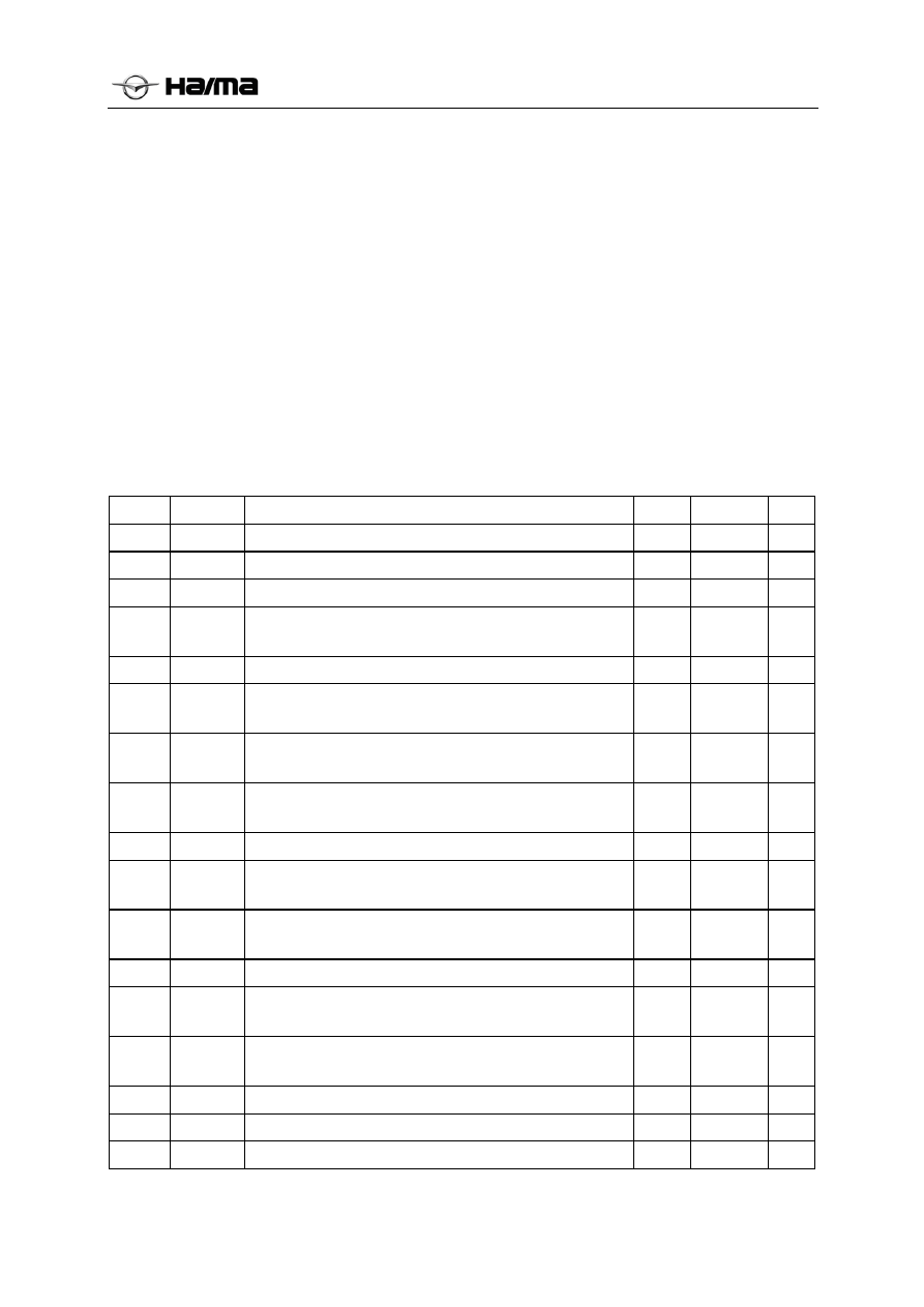
INDEX PCODES
UAES Explanations
CLASS MIL
SVS
1
P000A
Slow intake VVT response
5
×
×
2
P000B
Slow exhaust VVT response
5
×
×
3
P0010
VVT intake control valve circuit, open
3
√ ×
4 P0012
Intake VVT fails to stay at defaulted position when
starting
5 × ×
5
P0013
VVT exhaust control valve circuit, open
3
√ ×
6 P0015
Exhaust VVT fails to stay at defaulted position when
starting
5 × ×
7 P0016
Improper relative position between crankshaft and
camshaft
3
√ ×
8 P0017
Improper relative position between crankshaft and
camshaft
3
√ ×
9
P0030
Upstream oxygen sensor heater control circuit, fault
3
√ ×
10 P0031
Upstream oxygen sensor heater control circuit, low
voltage
3
√ ×
11 P0032
Upstream oxygen sensor heater control circuit, high
voltage
3
√ ×
12
P0036
Downstream oxygen sensor heater control circuit, fault
3
√ ×
13 P0037
Downstream oxygen sensor heater control circuit, low
voltage,
3
√ ×
14 P0038
Downstream oxygen sensor heater control circuit, low
voltage
3
√ ×
15
P0053
Upstream oxygen sensor heater resistance, improper
3
√ ×
16
P0054
Downstream oxygen sensor heater resistance, improper
3
√ ×
17
P0105
Intake pressure sensor signal, no fluctuation (freezing)
3
√ ×