Rover 214-414. Service Repair Manual - part 4
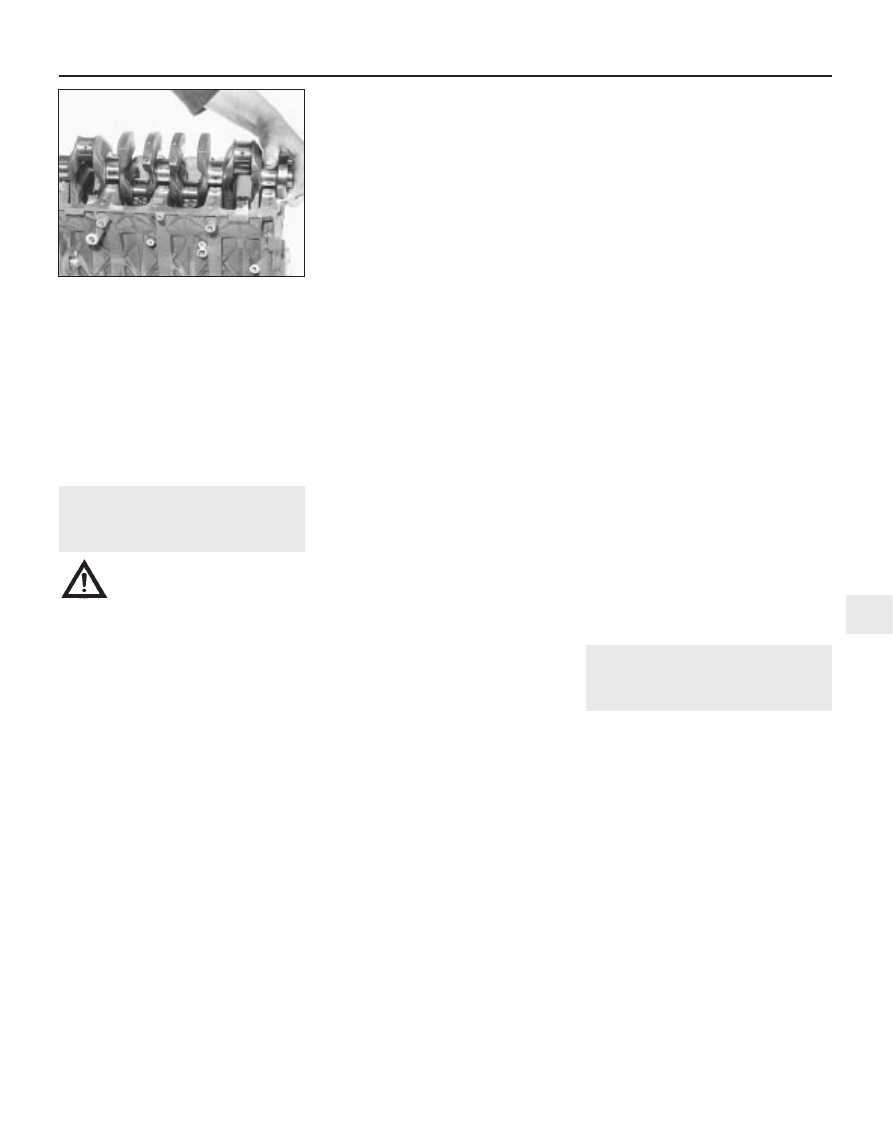
10 Remove the crankshaft (see illustration).
11 Withdraw the two thrustwashers from the
No 3 main bearing upper location. Noting the
position of the grooved shells, remove the
upper main bearing shells, which must be
kept with their correct respective partners
from the main bearing ladder so that all shells
can be identified and (if necessary) refitted in
their original locations.
12 Check the condition of the cylinder head
bolts, as described in Section 9.
11 Cylinder block/crankcase -
cleaning and inspection
4
Warning: Wear eye protection
when using compressed air!
Note: During any cleaning operations, take
care not to score the mating surfaces of the
cylinder block/crankcase, bearing ladder and
oil rail. It may be necessary to use a foam
action gasket remover.
Cleaning
1 For complete cleaning, remove the cylinder
liners, all external components and all
electrical switches/sensors.
2 Scrape all traces of gasket from the cylinder
block/crankcase, bearing ladder and oil rail,
taking care not to damage the gasket/sealing
surfaces.
3 Remove all oil gallery plugs (where fitted).
The plugs are usually very tight and may have
to be drilled out and the holes re-tapped. Use
new plugs when the engine is reassembled.
4 If any of the castings are extremely dirty, all
should be steam cleaned.
5 After the castings are returned, clean all oil
holes and oil galleries one more time. Flush all
internal passages with warm water until the
water runs clear, then dry thoroughly and
apply a light film of oil to all liner surfaces to
prevent rusting. If you have access to
compressed air, use it to speed up the drying
process and to blow out all the oil holes and
galleries.
6 If the castings are not very dirty, you can do
an adequate cleaning job with hot soapy
water and a stiff brush. Take plenty of time
and do a thorough job. Regardless of the
cleaning method used, be sure to clean all oil
holes and galleries very thoroughly and to dry
all components well. Protect the liners as
described above to prevent rusting.
7 All threaded holes must be clean to ensure
accurate torque readings during reassembly.
To clean all threads except those of the
flywheel retaining bolts, run the proper size
tap into each of the holes to remove rust,
corrosion, thread sealant or sludge and to
restore damaged threads. If possible, use
compressed air to clear the holes of debris
produced by this operation. A good
alternative is to inject aerosol-applied water-
dispersant lubricant into each hole, using the
long spout usually supplied. Always wear eye
protection when cleaning out holes in this
way. The flywheel retaining bolt threads must
be cleaned by using the procedure described
in Section 18, in Part A of this Chapter. Now is
a good time to check the condition of the
cylinder head bolts.
8 Apply suitable sealant to the new oil gallery
plugs and insert them into the holes in the
block. Tighten them securely.
9 If the engine is not going to be reassembled
right away, cover it with a large plastic bag to
keep it clean. Protect the liners as described
above to prevent rusting.
Inspection
10 Inspect all castings for cracks and
corrosion. Look for stripped threads. If there
has been any history of internal coolant
leakage, it may be worthwhile having an
engine overhaul specialist check the cylinder
block/crankcase with special equipment. If
defects are found, have them repaired, if
possible, or renew the assembly.
11 Check the bore of each cylinder liner for
scuffing and scoring.
12 Measure the diameter of each cylinder
liner bore 60 mm from the top of the bore,
both parallel to the crankshaft axis and at right
angles to it.
13 Compare the diameter with that specified.
If any measurement exceeds the service limit
then the liner must be renewed.
14 Measure the piston diameter at right
angles to the gudgeon pin axis, 16 mm up
from the bottom of the skirt. Compare the
results with those specified.
15 To measure the piston-to-bore clearance,
either measure the bore and piston skirt as
described above and subtract the skirt
diameter from the bore measurement, or
insert each piston into the original bore, select
a feeler gauge and slip it into the bore along
with the piston. The piston must be aligned
exactly in its normal attitude and the feeler
gauge must be between the piston and bore
on one of the thrust faces, 20 mm up from the
bottom of the bore.
16 If the clearance is excessive, then a new
piston will be required. If the piston binds
at the lower end of the bore and is loose
towards the top, then the bore is tapered. If
tight spots are encountered as the
piston/feeler gauge is rotated in the bore, then
the bore is out-of-round.
17 Repeat this procedure for the remaining
pistons and cylinder liners.
18 If the cylinder liner walls are badly scuffed
or scored, or if they are excessively worn, out-
of-round or tapered, obtain new cylinder
liners. New pistons will also be required.
19 If the bores are in reasonably good
condition and not worn to the specified limits,
and if the piston-to-bore clearances can be
maintained properly, then it may only be
necessary to renew the piston rings.
20 If this is the case, the bores should be
honed to allow the new rings to bed in
correctly and provide the best possible seal.
The conventional type of hone has spring-
loaded stones and is used with a power drill.
You will also need some paraffin, or honing
oil, and rags. The hone should be moved up
and down the bore to produce a crosshatch
pattern and plenty of honing oil should be
used. Ideally the crosshatch lines should
intersect at approximately a 60° angle. Do not
take off more material than is necessary to
produce the required finish. If new pistons are
being fitted, the piston manufacturers may
specify a finish with a different angle, so their
instructions should be followed. Do not
withdraw the hone from the bore while it is still
being turned, but stop it first. After honing a
bore, wipe out all traces of the honing oil. If
equipment of this type is not available, or if
you are not sure whether you are competent
to undertake the task yourself, an engine
overhaul specialist will carry out the work at
moderate cost.
12 Cylinder liners -
removal and refitting
Removal
1 Invert the cylinder block/crankcase and
support it on blocks of wood, then use a hard
wood drift to tap out each liner from the
crankshaft side. When all the liners are
released, tip the cylinder block/crankcase on
its side and remove each liner from the
cylinder head side. Discard the two sealing
rings from the base of each. If the liners are to
be re-used, mark each one by sticking
masking tape on its right-hand (timing belt)
face and writing the cylinder number on the
tape.
Refitting
2 To install the liners, thoroughly clean the
liner mating surfaces in the cylinder
block/crankcase and use fine abrasive paper
to polish away any burrs or sharp edges
which might damage the liner sealing rings.
Clean the liners and wipe dry, then fit new
sealing rings to the two grooves at the base of
each liner and apply a thin film of oil to the
Engine removal and general overhaul procedures 2B•9
10.10 Removing the crankshaft
2B
1689 Rover 214 & 414 Updated Version 09/97