Vauxhall Astra TwinTop (2007 year). Manual - part 17


  Index      Vauxhall     Vauxhall Astra TwinTop (2007 year) - manual in english


Search            copyright infringement  


Content      ..     15      16      17      18     ..


Vauxhall Astra TwinTop (2007 year). Manual - part 17


258

Self-help, vehicle care

If the specified tyre pressure is not 

reached within 10 minutes, remove the 

tyre repair kit. Move the vehicle through 

one tyre rotation, approx. 2 metres, in 

either direction. Reconnect the tyre 

repair kit and continue the filling 

process for 10 minutes. If the specified 

tyre pressure is still not reached, the tyre 

is too badly damaged. Park the vehicle 

and contact a workshop. 

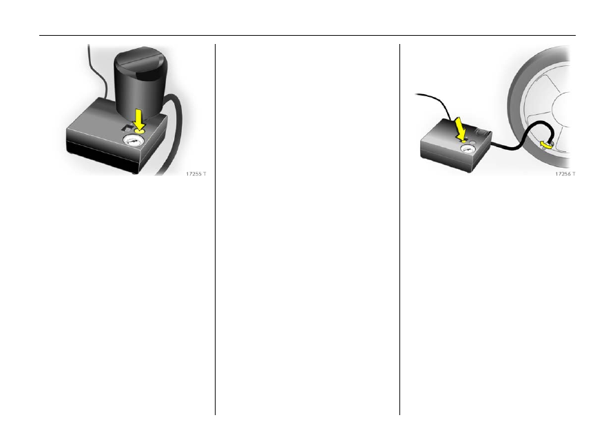
Drain excess tyre pressure with the 

button over the pressure indicator.
Do not run the compressor for more 

than 10 minutes - see "Important 

information" on page 259.

14. Detach the tyre repair kit. Screw the 

filler hose to the free connection on the 

sealant bottle. This prevents sealant 

leakage. Stow the tyre repair kit in the 

luggage compartment. 

15. Wipe away any sealant spill with a 

cloth.

16. Disassemble the warning triangle 3 

and store in luggage compartment, see 

page 247.

17. The enclosed sticker shows the 

maximum permitted speed at which the 

tyre repair may be used. Apply sticker in 

the driver’s field of vision. 

18. Continue driving immediately to allow 

the sealant to distribute evenly 

throughout the tyre. Stop after approx. 

6 miles/10 km (no more than 10 

minutes) and check tyre pressure. Screw 

the compressor air hose directly onto 

the tyre valve (see Fig. 17256 T). 

If tyre pressure is more than 1.3 bar, 

adjust to the prescribed value. Repeat 

the procedure until there is no more 

pressure loss. 
If the tyre pressure has fallen below 

1.3 bar, the vehicle may no longer be 

used. Contact a workshop. 

19. Stow the tyre repair kit in the luggage 

compartment, see page 256. 

-------------------------------------------------------------------------------------------------------------------------------------------------------------

259

Self-help, vehicle care

Important Information

The driving comfort of the repaired tyre is 

severely affected, therefore have this tyre 

replaced.
If the compressor makes abnormal noises 

or heats up greatly, switch it off for at least 

30 minutes.
The integrated safety valve opens at a 

pressure of 7 bar.
Protect the compressor from moisture and 

rain.

The sealant can only be stored for approx. 

4 years. After this time, the sealing 

properties can no longer be guaranteed. 

Heed the expiration date on the sealant 

bottle.
The sealant bottle can only be used once. 

Replace a used sealant bottle.
The compressor and sealant can be used 

from approx. -30 °C.
Dispose of a used tyre repair kit in 

accordance with applicable legislation.
The adapters supplied 3 can be used to 

inflate other items e.g. footballs, air 

mattresses, inflatable dinghies etc. 
They are located on the underside of the 

compressor. To remove, screw on 

compressor air hose and withdraw 

adapter. 
When using the tyre repair set, no 

consumers may be connected to the front 

accessory socket. 

Electrical system 

Fuses 

The vehicle has two fuseboxes: one behind 

a cover on the left side of the luggage 

compartment and one in the front left of 

the engine compartment. 

6

9

 Warning

Do not drive faster than 50 mph 

(80 km/h). 
Do not use the temporary spare wheel for 

a lengthy period. 
Steerability and driving behaviour may 

be impaired.

9

 Warning

Electronic ignition systems generate very 

high voltages. Do not touch the ignition 

system; high voltage can be fatal. 

-------------------------------------------------------------------------------------------------------------------------------------------------------------

260

Self-help, vehicle care

We recommend carrying a complete set of 

fuses. 
Put spare fuses in the provided location in 

the fusebox in the luggage compartment. 

Open cover, see page 262. 
Before replacing a fuse, turn off the 

respective switch and the ignition. 
A blown fuse (see figures to the right) can 

be recognised by its melted wire. Do not 

install a new fuse until the cause of the 

fault has been remedied. 

Different versions of fuses are used. 

Fuse,

Fuse,

colour

rating

Brownish yellow

5 A

Brown

7.5 A

Red

10 A

Blue

15 A

Yellow

20 A

Transparent 25 

A

Green

30 A

Fuse,

Fuse,

colour

rating

Blue

20 A

Transparent

25 A

Pink

30 A

Green

40 A

-------------------------------------------------------------------------------------------------------------------------------------------------------------

261

Self-help, vehicle care

There is a fuse extractor in the luggage 

compartment fusebox to facilitate 

replacement of fuses – see Fig. 17258 T for 

an example. 

Place the fuse extractor on the various 

types of fuse from the top or side, and 

withdraw fuse. 

Only fit fuses of the specified current 

rating. Each fuse has its current rating 

written on it, in addition the ratings are 

colour coded. 

-------------------------------------------------------------------------------------------------------------------------------------------------------------

262

Self-help, vehicle care

Fuses and the most important 

circuits they protect

Fusebox in luggage compartment

Depending on the equipment version, 

there are two different fuseboxes in the 

luggage compartment for differing 

electrical circuits. 

z Version A – see Fig. 18504 T on 

page 263. 

z Version B – see Fig. 17958 T on 

page 264. 

The Astra TwinTop always has version B
Spare fuses, fuse extractor, see page 259. 
The fusebox is located on the left side of 

the luggage compartment behind a cover. 
Do not store any objects behind the cover. 

5-door Hatch, Estate, Van

To open, turn both catches with a coin and 

fold cover down. 
3-door Hatch 

To open, fold the cover upwards. 

Astra TwinTop 

To open, pull the two knobs, remove the 

clips and fold the cover upwards. 

-------------------------------------------------------------------------------------------------------------------------------------------------------------

263

Self-help, vehicle care

Fusebox, version A

Some functions are protected by several 

fuses. To replace a fuse, pull off its 

protective cap.

Fusebox, version B

Some functions are protected by several 

fuses.

No. Circuit

Rating

Fog lights

15 A

– –
Luggage compartment 

socket

15 A

Reverse lights

7.5 A

Electric windows, rear

30 A

Air conditioning system

10 A 

Electric windows, front

30 A

Heated exterior mirrors 

7.5 A

No. Circuit

Rating

Electric windows, front

25 A

Instruments

7.5 A

Heating, 

air conditioning system, 

climate control system

5 A

Airbags 7.5 

A

10 

11 Heated rear window

25 A

12 Rear screen wiper

15 A

No. Circuit

Rating

13 Parking distance sensor

5 A

14 Heating, air conditioning 

system

7.5

15 

16 Seat occupancy 

recognition, 

Open&Start system 

5 A

17 Rain sensor, 

air quality sensor, 

tyre pressure monitoring 

system, 

interior mirror

5 A

18 Instruments, 

switches 

5 A

19 

20 CDC

10 A

21 Heated exterior mirrors 

7.5 A

22 Sunroof 20 

A

23 Electric 

windows, rear

25 A

-------------------------------------------------------------------------------------------------------------------------------------------------------------

264

Self-help, vehicle care

No. Circuit

Rating

24 Diagnostics plug 

7.5 A

25 

26 Electrically retractable 

exterior mirrors

7.5 A

27 Ultrasonic sensor, 

Vauxhall alarm system

5 A

28 

29 Cigarette lighter, 

front socket

15 A

30 Rear socket

15 A

31 

No. Circuit

Rating

32 

33 Open&Start system 

15 A

34 Sunroof,

TwinTop

25 A

35 Rear socket 

15 A

36 Towing equipment

20 A

37 

No. Circuit

Rating

38 Central locking system, 

terminal 30

25 A

39 Seat heater (left)

15 A

40 Seat heater (right)

15 A

41 

42 

43 

44 

-------------------------------------------------------------------------------------------------------------------------------------------------------------

265

Self-help, vehicle care

Fusebox in engine compartment 

The fusebox is at the front left side of the 

engine compartment. 

To open the cover, release the catch by 

inserting a screwdriver into the opening as 

far as it will go and swivelling it to the side. 

Open the cover upwards and remove. 

Depending on the equipment version, 

there are two different fuse layouts for the 

engine compartment fusebox, handling 

different electrical circuits: 

z If the luggage compartment fusebox is 

version A - see Fig. 18504 T on page 263  

- the fuse layout in the engine 

compartment is version A – see next 

column. 

z If the luggage compartment fusebox is 

version B - see Fig. 17958 T on 

page 264 - the fuse layout in the engine 

compartment is version B - see page 267. 

The Astra TwinTop always has version B
Spare fuses, fuse extractor, see page 259. 

Fuse layout, version A

Some functions are protected by several 

fuses. 

9

 Warning

Turn off engine before opening engine 

compartment fusebox; risk of injury, see 

page 297. 

No. Circuit

Rating

ABS

20 A

ABS

30 A

Interior fan climate control 

system

30 A

Interior fan, heating, 

air conditioning system

30 A

Radiator fan 1

1)

1)

Different ratings depending on engine 

and equipment level.

30 A

40 A

-------------------------------------------------------------------------------------------------------------------------------------------------------------

266

Self-help, vehicle care

No. Circuit

Rating

Radiator fan 2

1)

1)

Different ratings depending on engine 

and equipment level.

20 A 

30 A 

40 A

Central locking system 

20 A

Windscreen wash system, 

tailgate

10 A

Heated rear window, 

heated exterior mirrors

30 A

10 Diagnostics plug

7.5 A

11 Instruments

7.5 A

12 Mobile telephone, 

digital radio, 

Twin Audio, 

display

7.5 A

13 Courtesy light

5 A

No. Circuit

Rating

14 Windscreen wiper 

30 A

15 Windscreen wiper

30 A

16 Horn, ABS, 

brake light switch, 

air conditioning system

5 A

17 Diesel filter or 

air conditioning system

25 A 

20 A

18 Starter

25 A

19 

20 Horn

15 A

No. Circuit

Rating

21 Engine electronics

20 A

22 Engine electronics

7.5 A

23 Headlight range 

adjustment 

5 A

24 Fuel pump

15 A

25 

26 Engine electronics

10 A

27 Heating, 

air conditioning system, 

air quality sensor

7.5 A

28 

29 Power steering

5 A

30 Engine electronics

10 A

31 Rear screen wiper

15 A

32 Brake light switch

5 A

33 Headlight range 

adjustment, 

light switch, clutch switch, 

instrument assembly, 

driver’s door module

5 A

34 Control unit, 

steering column module

7.5 A

35 Infotainment system

20 A

36 Cigarette lighter, 

front socket

15 A

-------------------------------------------------------------------------------------------------------------------------------------------------------------

267

Self-help, vehicle care

Fuse layout, version B

Some functions are protected by several 

fuses. 
No. Circuit

Rating

ABS

20 A

ABS

30 A

Interior fan climate control 

system

30 A

Interior fan, heating, 

air conditioning system

30 A 

Radiator fan 1

1)

1)

Different ratings depending on engine 

and equipment level.

30 A 

40 A

Radiator fan 2

1)

20 A 

30 A 

40 A

No. Circuit

Rating

Windscreen wash system

10 A

Horn

15 A

Headlight wash system

25 A

10 

11 

12 

13 Fog lights

15 A

14 Windscreen wiper 

30 A

15 Windscreen wiper

30 A

No. Circuit

Rating

16 Electronics control units, 

Open&Start system, 

ABS, 

brake light switch, 

TwinTop

5 A

17 Diesel filter heating

25 A

18 Starter

25 A

19 Transmission electronics

30 A

20 Air conditioning system

10 A

21 Engine electronics

20 A

22 Engine electronics

7.5 A

23 Adaptive Forward Lighting, 

headlight range adjustment 

10 A

-------------------------------------------------------------------------------------------------------------------------------------------------------------

268

Self-help, vehicle care

No. Circuit

Rating

24 Fuel pump

15 A

25 Transmission electronics

15 A

26 Engine electronics

10 A

27 Power steering

5 A

28 Transmission electronics

5 A

29 Transmission electronics

7.5 A

30 Engine electronics

10 A

No. Circuit

Rating

31 Adaptive Forward 

Lighting, 

headlight range 

adjustment

10 A

32 Brake system, 

air conditioning system, 

clutch switch

5 A

33 Adaptive Forward 

Lighting, 

headlight range 

adjustment, 

light switch 

5 A

34 Control unit, 

steering column module

7.5 A

35 Infotainment system

20 A

36 Mobile telephone, 

digital radio, 

Twin Audio, 

display

7.5 A

-------------------------------------------------------------------------------------------------------------------------------------------------------------

269

Self-help, vehicle care

Bulb replacement 

Before replacing a bulb, switch ignition off 

and turn appropriate switch off. 
Only hold new bulb at base! Do not touch 

the bulb glass with bare hands, otherwise 

fingerprints on the glass evaporate. 

Residue builds up on the reflector 

eventually resulting in a dull reflector. 

Inadvertently stained bulbs may be 

cleaned with a clean lint-free cloth, using 

alcohol or white spirits. 
The replacement bulb must be in 

accordance with the data on the base of 

the defective bulb. Do not exceed wattage 

given on bulb base. 

The bulbs of the front outer lights are 

replaced through openings in the front 

wheel arches: turn appropriate wheels to 

gain access, release catch and remove 

cover. 
Headlight aiming 

We recommend that headlight adjustment 

be carried out by a workshop, who will 

have special equipment. 
On headlight adjustment, the manual 

headlight range adjustment 3 must be set 

to 0. 

Halogen headlight system 

Headlights with separate systems for main 

beam (inner bulbs) and dipped beam 2 

(outer bulbs). 

-------------------------------------------------------------------------------------------------------------------------------------------------------------

270

Self-help, vehicle care

Dipped beam 
1. Replace bulb through the opening in the 

front wheel arch: turn appropriate wheel 

to gain access, release catch and 

remove cover, see page 269. 

2. Remove headlight protective cover. 

3. Rotate left bulb holder and disengage. 

4. Remove the bulb holder with bulb from 

the reflector. 

-------------------------------------------------------------------------------------------------------------------------------------------------------------

271

Self-help, vehicle care

5. Detach bulb from bulb holder. 
6. Insert new bulb into bulb holder, 

without touching the glass. 

7. Insert new bulb so that the two lugs on 

the bulb holder engage in the recesses 

in the reflector. 

8. Rotate bulb holder to right as far as it 

will go. 

9. Place headlight protective cover in 

position and close. 

10. Position cover on opening in wheel arch 

and engage. 

Main beam 
1. Open bonnet and engage support. 
2. Replace bulbs from engine 

compartment out. 
To replace the bulb on the right-hand 

side, remove the air hose from the air 

filter. 
To replace the bulb on the left-hand 

side, remove the plug from the fusebox. 

3. Remove headlight protective cover. 
4. Detach plug connector from bulb. 

5. Disengage spring clip from retainer by 

pressing forward and then swing 

downward. 

6. Remove bulb from reflector housing. 
7. When fitting a new bulb, engage the 

lugs in the recesses on the reflector 

without touching the glass. 

-------------------------------------------------------------------------------------------------------------------------------------------------------------

272

Self-help, vehicle care

8. Engage spring wire clip, plug connector 

onto bulb. 

9. Place headlight protective cover in 

position and close. 
After bulb replacement on the right-

hand side, re-attach air hose to air filter 

and engage. 
After bulb replacement on the left-

hand side, reconnect the fusebox plug 

and engage. 

Parking lights 
1. Open bonnet and engage support. 
2. Replace bulbs from engine compartment 

out. 
To replace the bulb on the right-hand 

side, remove the air hose from the air 

filter. 
To replace the bulb on the left-hand 

side, remove the plug from the fusebox. 

3. Remove main beam headlight protective 

cover. 

4. Remove parking light socket from 

reflector. 

-------------------------------------------------------------------------------------------------------------------------------------------------------------

273

Self-help, vehicle care

5. Remove bulb from socket. 
6. Insert new bulb, without touching the 

glass.

7. Insert holder in reflector. Place headlight 

protective cap in position and close. 
After bulb replacement on the right-

hand side, re-attach air hose to air filter 

and engage. 
After bulb replacement on the left-hand 

side, reconnect the fusebox plug and 

engage. 

Xenon headlight system 

3

Adaptive Forward Lighting (AFL) 

system

3


Headlights with separate systems for 

dipped beam (inner bulbs) and main 

beam 2 (outer bulbs). 
Dipped beam 

Main beam 
1. Replace bulb through the opening in the 

front wheel arch: turn appropriate wheel 

to gain access, release catch and 

remove cover, see page 269. 

2. Remove headlight protective cover. 

9

 Warning

Dipped beam works with a very high 

electrical voltage. Do not touch, risk of 

injury. Have a workshop replace the bulb. 

-------------------------------------------------------------------------------------------------------------------------------------------------------------


Content      ..     15      16      17      18     ..