Saturn Transmission. Manual - part 22


  Index      Saturn     Saturn Transmission - service manual


Search            


Content   ..  20  21  22  23   ..


Saturn Transmission. Manual - part 22


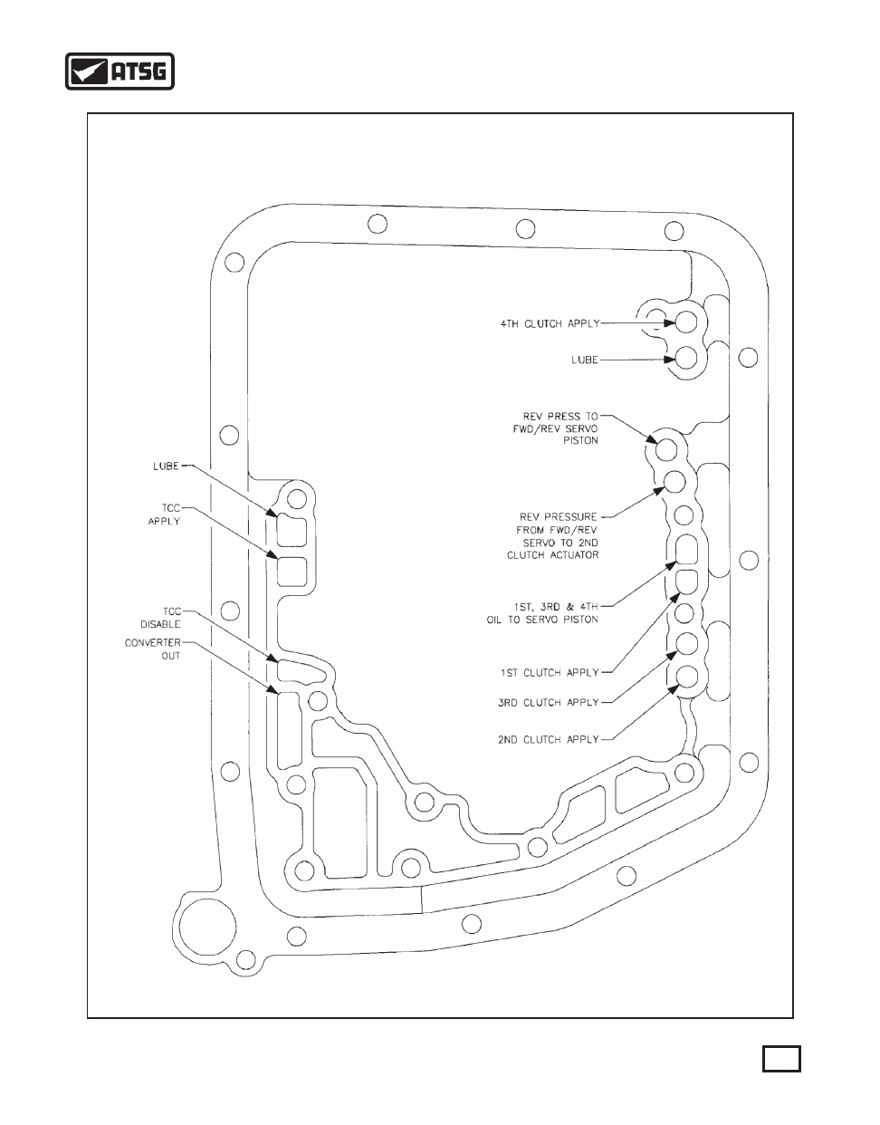
AIR PRESSURE TEST PORTS

2ND DESIGN CASE

91

AUTOMATIC TRANSMISSION SERVICE GROUP

Technical Service Information

Figure 212

Figure 213

   44. Install the manual valve link to the manual detent
         lever. It may be easier to start the roll pin in the
         detent lever before hand (See Figure 212).
   45. Attach the park pawl actuator rod to the manual
         detent lever and install it on the manual detent
         shaft lever (See Figure 212).
   46. Once the manual shaft is installed into the detent 
         lever, line up the roll pin hole and drive in the roll
         pin until it is flush (See Figure 212).
   47. 1994 vehicles with VIN # RZ141472 and higher 
         will not have a roll pin that attaches the manual 
         shaft to the detent lever. A retaining nut is used in 
         its place as shown in Figure 213. The installation 
         process is the same as described above. When the 
         nut is installed, torque the nut down to 12 N  m 
         (106 in. lbs). 
         IMPORTANT: For 1994, the manual valve link 
         has been changed from a stamped steel form to
         a one piece wire form link (See Figure 214).
         There is no change to the end of the manual
         valve link that is attached to the manual detent
         lever. BUT, the end of the manual valve link
         that attaches to the manual valve has increased
         in diameter from 3.85 mm (0.151 in.) to 4.92
         mm (0.194 in.). 


 48. The change in the valve link necessitated a change

         to the manual valve as well (See Figure 215). The
         manual valve link hole that the link attaches to
        

.

Figure 214

1991 & 1992

1st Design

1992 & 1993

2nd  Design

1994 & up

3rd Design

5.14 mm

(0.202 in.)

1991-1993
1st Design

1994 & up

2nd Design

3.85 mm (0.151 in.)

4.92 mm (0.194 in.)

3.92 mm

(0.154 in.)

FLAT

NOTCH

PLASTIC

CAP

Figure 215

3.92 mm

(0.154 in.)

92

AUTOMATIC TRANSMISSION SERVICE GROUP

Technical Service Information

         increased in diameter from approx. 3.92 mm
         (0.154 in.) to approx. 5.14 mm (0.202 in.).
         Additionally, a plastic cap has been put on the end
         of the manual valve. This cap is an assembly aid
         that prevents the manual valve from being
         installed to the manual valve link backwards.
         Functionally, the 1994 third design manual valve
         is the same as the 1992 and up second design
         manual valve.
         CAUTION: Never use a third design manual
         valve with a first design manual valve link.
         This will allow extra play in the linkage and
         could result in wrong gear engagements.


49. Install the Pattern Select Switch and retaining

         bolts. Do not tighten the retaining bolts at this
         time (See Figure 216).
   50. Install the external manual lever to the manual 
         lever shaft as shown in Figure 216 and tighten the 
         retaining nut to 12 N  m (106 in. lbs).
         NOTICE: When tightening the nut on the 
         manual shaft, be sure to hold the shaft from 
         rotating to prevent damage to the selector switch.


51. Install the valve body to the case (See Figure 217).

         Make sure the manual valve is oriented with flat 
         or notch facing up (See Figure 215).
   52. Attach the manual valve to the manual valve link
         and set the valve body into position on the case.
   53. Align the valve body to the case using the dowel
         bolts shown in Figure 218.
   54. Start all valve body bolts by hand and torque the
         bolts to 11 N  m (97 in. lbs) in the numerical 
         sequence shown in Figure 218.

Figure 216

Figure 217

8

DOWEL BOLT

10 11

3

9

DOWEL BOLT

1

2

4

5

6

7

Figure 218

.

.

93

AUTOMATIC TRANSMISSION SERVICE GROUP

Technical Service Information

Figure 219

Figure 220

Figure 221

9

1

5

11

3

8

13

6

2

10

12

4

7

SPIRAL RING

O RING

Figure 222

CONT.

   55. Adjust the neutral safety switch by placing the 
         manual lever into the D4 position. Place an 
         ohmmeter on the two terminals in the connector 
         shown in Figure 219. Rotate the switch until 
         continuity is seen. Tighten the retaining bolts to 
         14 N  m (124 in. lbs).
   56. After the switch retaining bolts have been torqued,
         check for continuity again to ensure the switch
         maintained adjustment.
   57. Install a new valve body cover gasket onto the 
         case (See Figure 220).
   58. Carefully place the valve body cover pan onto the
         case being careful not to damage the actautor
         connector (See Figure 220).
   59. Hand start all cover bolts and torque each bolt to 
         10 N  m (89 in. lbs) in the numerical sequence 
         shown in Figure 221.
   60. Install a new converter O ring on the input shaft.
         Make sure the O ring is behind the spiral ring
         on models that use it. (See Figure 222). 
   61. Lubricate the input shaft O ring with petroleum 
         jelly.
   62. If the spiral ring was removed, install a new spiral
         ring using Saturn's installation tool SA9135T or
         equivalnet as shown in Figure 223.
   63. Install converter housing to case bolts and torque
         them down to 25 N  m (18 ft. lbs) as shown in
         Figure 224. 
   64. Using transmission fluid, lubricate the filter seal.
         Spin the filter  on until the seal makes contact to
         the case and tighten one complete turn (See Figure
         225).
         IMPORTANT: DO NOT TIGHTEN FILTER 
         WITH A FILTER WRENCH. DAMAGE TO
         THE FILTER WILL OCCUR. 

.

.

.

94

AUTOMATIC TRANSMISSION SERVICE GROUP

Technical Service Information

The spiral ring was eliminated on 97 up. The "O"-ring 

groove width was reduced from .189" to .140"


Content   ..  20  21  22  23   ..