Porshe 911 (997). Manual - part 30


  Index      Hummer     Porshe 911 997 series - service repair manual 2004-2008 year


Search            


Content   ..  28  29  30  31   ..


Porshe 911 (997). Manual - part 30


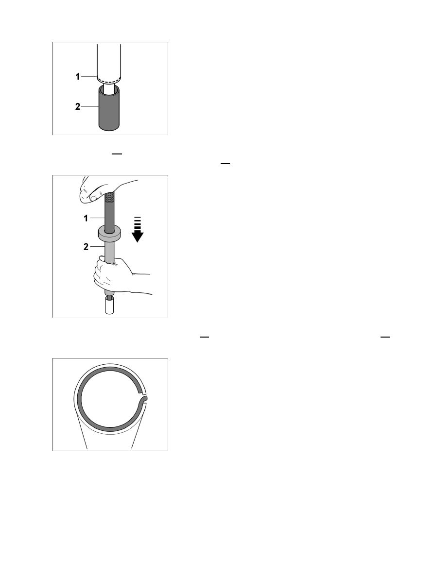
Assembly tool on piston pin

43. Oil piston pin -3- with new engine oil and place it in an upright position on a clean surface on the

workbench. Position assembly tube with circlip -1- and pressure pin on piston pin.

Moving piston-pin circlip into installation position

44. Press piston-pin circlip with pressure pin -1- onto piston pin; while doing so, press assembly tube -2-

firmly onto piston pin. This will move the piston-pin circlip into the correct installation position.

Installation position of piston-pin circlip in assembly tube

45. Check installation position of piston-pin circlip in assembly tube.

Diagnostic system: reading out fault memory and activating systems

Installing pistons

277

Piston pin and circlip on assembly tool 9602/1

46. Insert assembly tool 9602/1 with piston pin circlip and piston pin through the centring aid 9602/5 into

the crankcase. Press piston pin into assembly bore of piston/connecting rod eye.

Position of assembly tube on centring aid 9602/5

47. Groove in assembly tube must sit on dowel pin of centring aid 9602/5.

Inserting piston-pin circlip in cylinder 6

48. Push the piston pin circlip to its installation position by briefly and forcefully striking the palm of

your hand against the star knob of the pressure pin.

Seating of piston-pin circlip

Diagnostic system: reading out fault memory and activating systems

Installing pistons

278

49. Using a mirror, check that the piston-pin circlip is seated correctly.

ATTENTION

Incorrect and careless assembly of pistons.

Component damage (pistons, piston rings, cylinder line)

• 

→ Assemble pistons carefully and gently.

→ Stop process immediately if there is increased resistance during assembly; eliminate the cause of the

problem.

50. Repeat steps 35- 49 carefully to assemble pistons 5 and 4. During this process, the crankshaft is

fixed to the crankcase through bore U5 for cylinder 5 and through bore U4 to the belt
pulley/vibration balancer. Convert the assembly tool 9602/1 as described below.

Spacer sleeve for cylinder 5

51. Push a spacer sleeve onto the assembly tube for the assembly of pistons pins and circlip on cylinder 5.

Inserting piston-pin circlip for cylinder 5

52. Fit the piston-pin circlip for cylinder 5 using a sleeve.

Diagnostic system: reading out fault memory and activating systems

Installing pistons

279

Spacer sleeves for cylinder 4

53. Push two spacer sleeve onto the assembly tube for the assembly of pistons pins and circlip on cylinder 4.

Inserting piston-pin circlip in cylinder 4

54. Fit the piston-pin circlip for cylinder 4 using two sleeves.

Screw plug for assembly bore in crankcase

55. Once the pistons have been installed, seal the bore for the piston pin and circlip assembly on the

crankcase using the aluminium screw plug and new sealing ring. → Tightening torque: 59 ftlb.

Installing pistons, touching up

Installing pistons, touching up

1. Assemble engine → 100137 Disassembling and assembling engine - "Assembling"

section.

997110, 997111, 997120, 997121, 997310, 997311, 997320, 997321, 997410, 997411, 997430, 997431,
997610, 997611, 997620, 997621

Diagnostic system: reading out fault memory and activating systems

 Installing pistons, touching up

280


Content   ..  28  29  30  31   ..