Engine International HS 2.8L. Manual - part 11
International HS 2.8L
Cylinder Head
5 1
8120081 - 05/02 - Service Manual
INTERNATIONAL ENGINES
Reinstallation
1.
Make sure that the engine block surface is
perfectly clean.
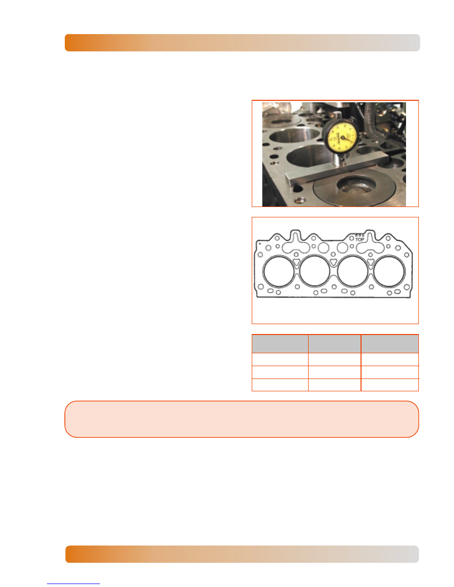
2.
Using a dial indicator gauge with a magnetic
base, check pistons height, to specify the
cylinder head gasket.
3.
There are available 3 (three) types of gaskets
for the cylinder head assembly, identified by
holes in the left side, from front viewing.
Note:
Cylinder head gasket corresponds to piston height, in relation with cylinder head
surface.
4.
Select a new gasket with the correct
thickness.
Holes
reference
Gasket
thickness
Piston Height
(mm)
0
1.37 mm
from 0.50 to 0.60
00
1.48 mm
from 0.61 to 0.70
000
1.59 mm
from 0.71 to 0.80