Автомобили BAW. Руководство - часть 51


  Главная      Учебники - Транспорт     Автомобили BAW - руководство по эксплуатации и ремонту


поиск по сайту            


содержание   ..  49  50  51  52   ..


Автомобили BAW. Руководство - часть 51


replace the seal and the other broken components.         

 Notice:                                                                               

  Do not use the dismounted seals again. 

  Seal should keep the open-end entad when they were mounted. 

4.2 

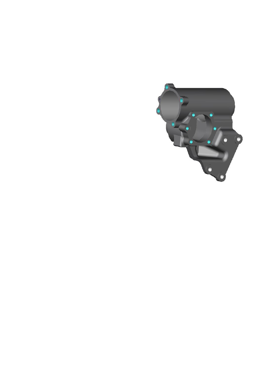
Check the housing (Figure 4)   

4.2.1  Inspect the bore of housing and 

matching surface. If there is the 

light  abrasion  mark  in  the  hole 

wall  that  is  normal.  If  there  is 

scuffing  or  heavy  wear  in  the 

hole wall or assembly matching 

surface, should replace housing. 

If housing is in 

good condition 

but  needle  roller  bearing  is 

broken,  should  replace  housing 

too.                                                                            Figure 4   

4.2.2  Inspect  whether  there  is  damnification  of  outside  diameter  of 

surface of seals. If damnification appeared on the external diameter, 

then  inspect whether there  is burr  in the  inwall  of  housing, should 

remove all burrs before install the new “O” ring.   

4.2.3  Inspect whether the surfaces of closed cell have been worn, should 

replace the housing if they were worn. 

4.3 

Assembly of housing components. (Figure 3) 

4.3.1  Clean the housing and “O” ring and other parts completely. 

4.3.2  Use  power  steering  fluid  lubricate  hole  of  housing,  bearing  and 

“O” ring. 

4.3.3  Use  bearing  installation  tool  to  install  needle  bearing  (If  bearing 

need to be replaced). 

4.3.4  Use  installation  tool  enclose  seal  components  (2),  Teflon  ring


(3) 

and “O” ring (4) in the hole of housing. 

4.3.5  Use  special  tool  carefully  enclose  the  dust  ring  seal  (5)  into  the 

hole of housing. The replace process of housing should complete in 

manufacturing  factory,  maintenance  stations  don’t  have  the 

condition to finish the work. 

5.  Valve housing components (Figure 5) 

Inspect of valve housing components. 

Dismount  every  part  according  to  the 

figure,  use  cleaning  agent  wash  all  the 

parts,  then  let  compressed  air  blow  all  the 

passageways. Inspect hose connection, if it 

has  been  damnified,  ruptured  or  worn 

seriously  then  replace  it  according  to  the 

requirement  of  hose  connection.  If  every 

seal has broken then replace it.                                    Figure 5       

6.  Rotary  spool  valve-worm  and  ball  nut 

components (Figure 6) 

Inspect  rotary  spool  valve-worm  and  ball 

nut components. 

Inspect  tooth  surface  and  outside  surface  of 

steering ball nut, if there is serious abrasion, 

abrade or drop pit on the part, should replace 

it.  There  is  light  furbish  on  the  surface  of 

valve body is allowed.                                                      Figure 6           

Admonition: 

Worm,  ball  nut,  grinding  ball  and 

valve  components  of  the  rotary 

spool  valve-worm  and  ball  nut 

components is  the  exact  fitting, do 

not 

allow 

disassembling. 

Otherwise,  it  will  break  the  whole 

component. 

7.  Pitman 

arm 

shaft-side 

cover 

components (Figure 7)                                                Figure 7 

7.1 

Clean all the  feculence, rusteaten and corrosive on the pitman arm 

shaft by crocus cloth, scouring seal position and wash all the parts. 

7.2 

Inspect support surface of side cover (6), support surface of pitman 

arm  (3), sector  gear of  pitman arm shaft (2), surface of seal (1),  if 

there  is  serious  abrasion,  crack,  abrade  or  drop  pit,  should  replace 

pitman arm shaft components. If adjust screw of  pitman arm shaft 

(5)  loose  or  worn  too  much,  should  replace  pitman  arm  shaft 

components.  If  the  seal  ring  of  side  cover  (6)  was  broken,  replace 

by new one.   

8.  Complete assembly of steering gear. (Figure 8, 9 10) 

 Notice: According to the stated process and order to adjust strictly 

as flowing, otherwise is able to break components of steering gear 

and weaken the susceptiveness of steering gear.   

Complete assembly of steering gear. 

8.1 

Lubricate  all  the  matching 

surfaces  by  power  steering 

fuild. (Figure 8) 

8.2 

Inspect  whether  the  seal 

rings  in  the  hydraulic  fluid 

connection  grooves  of  valve 

body  have  popped  out  or 

missing,  could  use  a  spot  of 

grease  substance  affix  this 

seal ring make it stick to slot 

wall. 

8.3 

While  enclose  the  thrust  ball  bearing  (2)  into  valve  housing 

components (1), be careful: 

 The  bearing  component  composed  of  three  parts,  should  keep 

they are corresponding one to one during the assembly process. 

Thereinto,  the  inside  diameter  of  two  bearing  supports  is 

Figure 8


different,  enclose  the  one  with  a  big  bore  first  and  put  it  into 

valve  housing  (1)  completely  and  cling  to  inner  end  surface  of 

valve housing. 

 During the next assemble process, care should be taken that the 

steering  shaft  avoid  any  axial  thrust,  and  keep  compaction 

between steering bearing and valve housing all the time for fear 

every part of bearing unhitch or disturb. 

8.4 

Install the valve components on the valve, keep the  medial rack of 

steering  ball  nut  align  to  bearing  hole  center  of  pitman  shaft  and 

keep  upper  oil  port  of  valve  housing  align  to  oil  return  hole  of 

housing,  then  thrust  rotary  spool  valve-screw  and  nut  components 

into 

housing 

slowly 

(4), 

and 

use 

hexagon 

bolt 

(GB/T5786-1986-M12 × 1.5 × 30)  (5)  and  spring  washer 

(GB/T93-1987  12)  (6)  join  the  valve  housing  with  housing, 

tightening  torque  is  80  N·m~90  N·m.  Keep  the  gullet  of  rack 

center of steering nut lies on output shaft center of housing. 

8.5 

(Figure  9)  Assemble  pitman 

arm  shaft  components  (5)  with 

side  cover  components  (4) 

together,  turn  the  side  cover  as 

entad as possible, mount nut (1) 

on  the  adjust  screw  of  pitman 

arm  shaft  components  and  do 

not  screw  to  the  end.  Then 

enclose  the  components  to 

housing  (6).  Thereinto,  should 

adjust  the  position  of  steering 

ball nut when assembly, ensure                                            Figure 9                     

medial  sector  gear  of  pitman  arm  shaft  engage  with  the  medial 

gullet  of  steering  nut.  Finally,  use  six  light  spring  washer 

GB/T859-1987 10 (3) and hexagon bolt (2) join the side cover with 


содержание   ..  49  50  51  52   ..