Kubota tractor (BX25DLB-AU, LA240A, LA240A, AU-SG, BT602). OPERATOR'S MANUAL - part 24


  Index      Tractors     Kubota tractor (BX25DLB-AU, LA240A, LA240A, AU-SG, BT602). OPERATOR'S MANUAL


Search            copyright infringement  


Content   ..  22  23  24  25   ..


Kubota tractor (BX25DLB-AU, LA240A, LA240A, AU-SG, BT602). OPERATOR'S MANUAL - part 24


65

OPERATING THE LOADER

ATTACHING ATTACHMENTS

[Option for LA240A, LA240A AU-SG]

A

Attachments should be located on a flat, firm surface
when attaching and detaching them from the BX6315
or LA243A AU-SG Quick Coupler.

1. Remove Hitch Pins and Snapper Pins from the Hitch

Pin Bosses on the BX6315 or LA243A AU-SG Quick
Coupler.

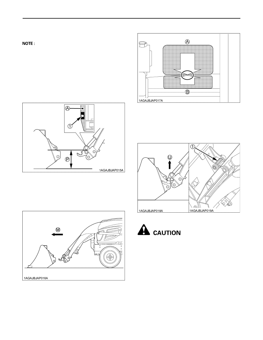
2. Move the loader control lever to the "dump" position

until the surface with the arrow marker on the BX6315
or LA243A AU-SG Quick Coupler label gets in parallel
with the ground as shown in the following illustration.

3. Move the tractor forward slowly until the arrow marker

on the attachment label is close to that on the Quick
Coupler label.

[When viewed from the operator's seat]

4. Raise the boom of the loader until the pin at the upper

bosses of the attachment seat in the Quick Coupler
receivers, and the rear of the attachment is raised
slightly off the ground.

To avoid personal injury:
A

Do not raise attachment completely off the
ground at this point. the attachment could
swing off the quick coupler.

(1) Arrow marker

(A) Position this surface in 
      parallel with the ground.
(P) "PARALLEL"

(M) "MOVE FORWARD SLOWLY"

(A) Front attachment side
(B) Quick Coupler side

(1) Pin 3

(U) "UP" position

OPERATING THE LOADER

66

5. Keeping the attachment at ground level, move the

loader control lever to the "roll back" position until the
cylinders stop. Turn off the engine and set the parking
brake.

6. Install both Hitch Pins and Snapper Pins as shown in

the following illustration.
The illustration shows a properly attached bucket.

To avoid personal injury:
A

Make sure both hitch pins and snapper pins are
properly installed before moving or operating
attachments.

A

Keep hitch pins and snapper pins assembled in
the BX6315 or LA243A AU-SG quick coupler at
all times, even if no attachment is being used.

A

Replace any pins or other parts which are lost
or broken.

7. You are now ready to use the attached attachment.

Compatible attachments can be attached and
detached using the same method. 

To avoid personal injury:
A

Never operate or transport attachments which
are not attached completely.

A

Always replace damaged hardware
immediately.

(A) Hitch Pins
(B) Snapper Pins

67

OPERATING THE LOADER

DETACHING ATTACHMENTS

[Option for LA240A, LA240A AU-SG]
1. Detaching the attachments is done in the reverse of

attaching attachments.

2. Lower the implement and roll it back completely. Stop

the engine and set the parking brake.

3. Remove Hitch Pins and Snapper Pins.
4. While sitting in the tractor operator's seat, start the

engine and slowly move the loader control lever to the
"dump" position. The attachment will be pushed away
slightly from the Quick Coupler.

5. Lower the loader boom so the receivers of the Quick

Coupler clear the bottom of the Upper Pins.

6. Back away from the attachment slowly.
7. Reinstall Hitch Pins and Snapper Pins in the BX6315

or LA243A AU-SG Quick Coupler, even if no
attachment is used.

DISMOUNTING THE LOADER

[Option for LA240A, LA240A AU-SG]

To avoid machine damage or personal injury:
A

Remove loader from tractor only when an
approved loader bucket is attached.

Follow instructions provided in "REMOVING THE
LOADER" section in this operator's manual.

ATTACHMENTS

[Option for LA240A, LA240A AU-SG]

B

Bucket

Rigid type square 48" bucket can be used as quick
buckets for BX6315 or LA243A AU-SG quick coupler.

B

Pallet fork

(1) Rigid type square 48" bucket

LOADER MODEL

RATED CAPACITY

LA240A, LA240A AU-SG

310 LBS.

OPERATING THE LOADER

68

ASSEMBLE PALLET FORK

[Option for LA240A, LA240A AU-SG]
1. Install the fork to the middle of the frame.

(fit the lower hook of the fork to the center notch of the
frame)

2. Slide the fork to the desired position.

3. Push the lock lever and slide the fork slightly until the

lock pin engages with one of the notches to lock the
folk.

4. The other fork can be installed using the same

procedures.

(1) Fork

(1) Fork

(1) Lock lever


Content   ..  22  23  24  25   ..