Snowmobile Ski Doo REV SERIES (2004 year). Manual - part 67
Section 07 ELECTRICAL SYSTEM
Subsection 03 (BATTERY)
BATTERY CHARGE TESTING
Voltmeter Test
NOTE: To determine the battery state of charge,
these sealed batteries have to be tested with a
voltmeter. They also need to be tested when their
voltage is stabilized. Disconnect battery to have
open connectors and wait 1-2 hours prior to read-
ing the voltage. The same condition is required
after a battery has been charged.
Batteries with a voltage above 12.8 V do not need
to be charged.
Batteries with a voltage of 12.8 V and below need
to be charged. Refer to BATTERY CHARGING be-
low.
BATTERY STORAGE
CAUTION: A discharged battery will freeze and
it may damage its casing. A damaged casing
will allow electrolyte spillage that may damage
surrounding parts.
Disconnect and remove battery from the vehicle.
The battery must always be stored in fully charged
condition.
Clean battery terminals and cable connections us-
ing a wire brush. Apply a light coat of dielectric
grease (P/N 293 550 004) or petroleum jelly on ter-
minals.
Clean battery casing using a solution of baking
soda and water. Rinse battery with clear water
and dry well using a clean cloth.
Charge the battery every month if stored at tem-
perature below 15°C (60°F).
Charge the battery every two week if stored at
temperature above 15°C (60°F).
ACTIVATION OF NEW BATTERY
Refer to the instructions provided with the battery.
BATTERY CHARGING
WARNING
Always wear safety glasses and charge in
a ventilated area.
Never charge or boost
battery while installed on vehicle. Do not
open the sealed caps during charging. Do
not place battery near open flame.
CAUTION: If battery becomes hot, stop charg-
ing and allow it to cool before continuing.
NOTE: Sealed VRLA batteries have an internal
safety valve. If battery pressure increases due to
overcharging, the valve opens to release excess
pressure, preventing battery damage.
Perform BATTERY CHARGE TESTING above then
proceed as described here.
An automatic charger is the fastest and most con-
venient way for error-proof charging.
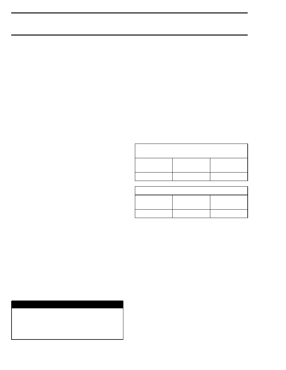
When using a constant current charger, charge
battery according to the chart below.
Battery Voltage Below 12.8 V
and Above 11.5 V
STANDARD CHARGING
(recommended)
BATTERY
TYPE
TIME
CHARGE
YTX20L-BS
4–9 hours
2 A
QUICK CHARGING
BATTERY
TYPE
TIME
CHARGE
YTX20L-BS
50 minutes
10 A
Battery Voltage Below 11.5 V
Batteries with voltage below 11.5 V requires
special procedures to recharge. In charging an
overdischarged battery, its internal resistance
may be too high to charge at a normal charging
voltage. Therefore, it may be necessary to raise
the voltage of the battery initially to 25 V as a max-
imum, and charge for approximately 5 minutes.
If the charger ammeter shows no change in cur-
rent after 5 minutes, you need a new battery. Cur-
rent flowing into the battery at high voltage can
become excessive. Monitor amperage and adjust
voltage as necessary to keep current at the bat-
tery’s standard amp rating. Charge for approxi-
mately 20 hours.
INSTALLATION OF BATTERY
Reinstall battery and secure bracket properly.
260
mmr2004-Rev