Snowmobile Arctic Cat 2-Stroke (2007 year). Manual - part 101


  Index      Snowmobiles / ATV     Snowmobile Arctic Cat 2-Stroke - service manual 2007 year


Search            


Content   ..  99  100  101  102   ..


Snowmobile Arctic Cat 2-Stroke (2007 year). Manual - part 101


8-24

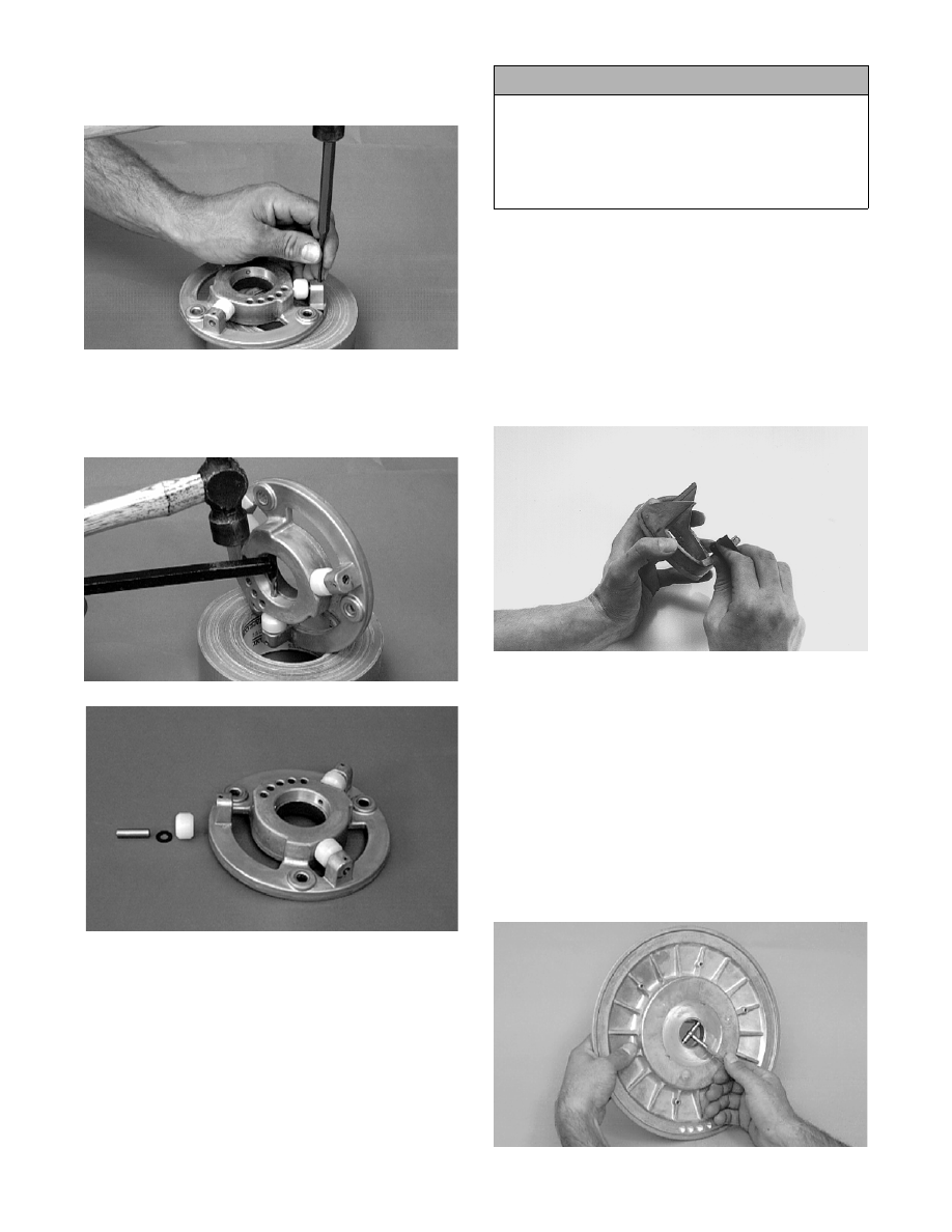
8. Using a 1/8-in. punch, remove the spring pin

securing the roller, roller pin, and thrust washer to

the plate.

SC005D

9. Using the Roller Pin Removal Tool (p/n 0644-276)

from inside the plate, drive the roller pin out of the

plate. Account for the pin, thrust washer, and

roller.

SC006D

SC007D

CLEANING AND INSPECTING

„NOTE: Whenever a part is worn excessively,
cracked, or damaged in any way, replacement is
necessary.

1. Using parts-cleaning solvent, wash grease, drive

belt dust, and foreign matter off all components.

2. Inspect the rollers for damage, cracks, or wear.

3. Inspect the sheaves for any gouges, cracks, or

other damage. Also, inspect threaded areas of

sheaves for damaged or stripped threads.

4. Inspect the torque bracket (cam) for cracks or

damage. The ramp portions of the bracket and

caps must be free of gouges and damage. Minor

scratches may be repaired using #320 grit wet-or-

dry sandpaper.

B465

5. Inspect spring for distortion, crystallization, or

breaks.

6. Inspect the roller plate, rollers, pins, and spring

mounting holes for cracks, damage, or wear.

7. Inspect the roller plate and movable sheave bear-

ings for wear. For each respective bearing, mea-

sure the outside diameter of the shaft and the

inside diameter of the bearing. Compare the read-

ings. Clearance between the shaft and the respec-

tive bearing must not exceed 0.5 mm (0.020 in.). If

the clearance exceeds the specification, the bear-

ing must be replaced.

B466D

! CAUTION

Do not use steel wool or a wire brush to clean driven
pulley components. A wire brush or steel wool will
cause the sheaves to be gouged (thus, the drive belt
may not slide properly between sheaves). Decreased
performance and possible accelerated drive belt
wear will result.

8-25

8

B467

REMOVING BEARINGS

To remove driven pulley bearings, use the Bearing

Removal and Installation Tool (p/n 0644-167) and the

following procedure.

„NOTE: To remove the movable sheave bearing,
heat must be applied around the bearing.

1. Place the movable sheave (or roller plate) flat on a

press.

2. Using the bearing tool, press the bearing out.

AF154

INSTALLING BEARINGS

„NOTE: Before installing a bearing, apply red Loc-
tite #271 to the outside face of the bearing.

1. Place the movable sheave (or roller plate) flat on a

press.

2. Using the bearing tool, press the bearing into posi-

tion. The bearing must be flush with the outside of

the bearing boss.

3. Wipe off excess Loctite. Allow the Loctite to cure

for 24 hours at room temperature.

ASSEMBLING

1. Place the roller and thrust washer (toward the out-

side of the roller plate) and secure with the roller

pin.

2. Secure the roller, thrust washer, and pin into posi-

tion with the spring pin. Drive the pin in until it is

flush with the plate.

SC012D

3. Place the torque bracket (cam) into position on the

stationary sheave making sure the degree number

on the bracket aligns with the part number on the

stationary sheave. Install the three socket head

screws and lock washers. DO NOT tighten at this

time.

AI062

4. Place any thrust washers (as noted during disas-

sembly) on the stationary sheave shaft.

B460

! WARNING

Always wear safety glasses when using the bearing
driver.

8-26

5. Align the scribed line made during disassembly;

then slide the movable sheave onto the stationary

sheave shaft.

B459D

6. Place the sheaves on a work fixture (roll of duct

tape, etc.).

7. Place the spring over the stationary sheave hub

and hook the turned down end of the spring into

the hole in the casting of the stationary sheave.

B458D

8. Place the roller plate over the spring and hook the

turned-up end of the spring in the 3rd hole (stan-

dard spring tension) of the plate.

9. While holding the sheaves to prevent them from

rotating, grasp the roller plate and rotate it approx-

imately 120° clockwise until the mounting holes

align; then push the plate into position and install

the three lock nuts. Tighten the lock nuts to speci-

fications.

„NOTE: The line scribed during disassembly
should be aligned.

SC003D

10. Rotate the movable sheave to ensure free move-

ment without binding.

11. Rotate the torque bracket (cam) until it is tight;

then using a long hex wrench, tighten the three

socket-head cap screws (from step 3) securing the

bracket to specifications.

SC011D

INSTALLING

1. Slide the alignment washers onto the end of the

driven shaft.

2. Install the key in the driven shaft keyway; then

place the stub shaft into the driven pulley. Place

the driven pulley on the shaft. Align its keyway

with the driven shaft keyway.

„NOTE: A small amount of Loctite Anti-Seize
Thread Compound (p/n 0678-146) applied to the
driven shaft will aid in future driven pulley
removal.

3. Secure the driven pulley by installing any align-

ment washers, the washer, and cap screw (coated

with blue Loctite #243). Tighten the cap screw to

specifications.

8-27

8

SC013D

4. Check drive clutch/driven pulley alignment (see

Drive Clutch/Driven Pulley in this section); adjust

as necessary.

5. Install the drive belt and check drive belt deflec-

tion (see Drive Clutch/Driven Pulley in this sec-

tion). Secure the belt guard.

Drive Clutch/

Driven Pulley 

(STD)

CHECKING OFFSET

If premature drive belt wear is experienced or if the

drive belt turns over, parallelism/offset must be

checked. Also, parallelism/offset must be checked

whenever either the drive clutch or driven pulley is

serviced. To check the parallelism/offset, use the

Clutch Alignment Bar (p/n 0644-320) and the follow-

ing procedure.

1. Open the belt guard and remove the drive belt.

2. Install the clutch alignment bar between the drive

clutch sheaves and against the outside edge of the

driven pulley stationary sheave.

3. Allow the alignment bar to rest on the drive clutch

shaft.

0733-912

„NOTE: The alignment bar must extend beyond
the front edge of the drive clutch.

4. With the bar against the outside edge of the driven

pulley stationary sheave at points A and B, the bar

should just clear the inside edge of the stationary

sheave of the drive clutch and rest on the station-

ary shaft. If the bar does not clear the inside edge

or is more than 1.5 mm (0.060 in.) from the inside

edge, the offset must be corrected.

AF465D

733-912B

CORRECTING OFFSET

1. To correct offset, the driven pulley must be moved

laterally on the driven shaft. Remove the cap

screw and washers securing the driven pulley; then

remove the driven pulley.

„NOTE: If the driven pulley is tight on the driven
shaft, pull the driven pulley off using the Driven
Pulley Puller (p/n 0744-023).

2. To move the driven pulley inward on the shaft,

remove washer(s) as required from behind the pul-

ley.

3. To move the driven pulley outward on the shaft,

add alignment washer(s) as required behind the

driven pulley.

„NOTE: Make sure the keyways match when
installing the driven pulley. Arrange washers to
allow the least amount of “float” on the driven
shaft. A maximum of 1.5 mm (0.060 in.) of float is
acceptable.


Content   ..  99  100  101  102   ..