Snowmobile Arctic Cat 2-Stroke (2007 year). Manual - part 47


  Index      Snowmobiles / ATV     Snowmobile Arctic Cat 2-Stroke - service manual 2007 year


Search            


Content   ..  45  46  47  48   ..


Snowmobile Arctic Cat 2-Stroke (2007 year). Manual - part 47


2-174

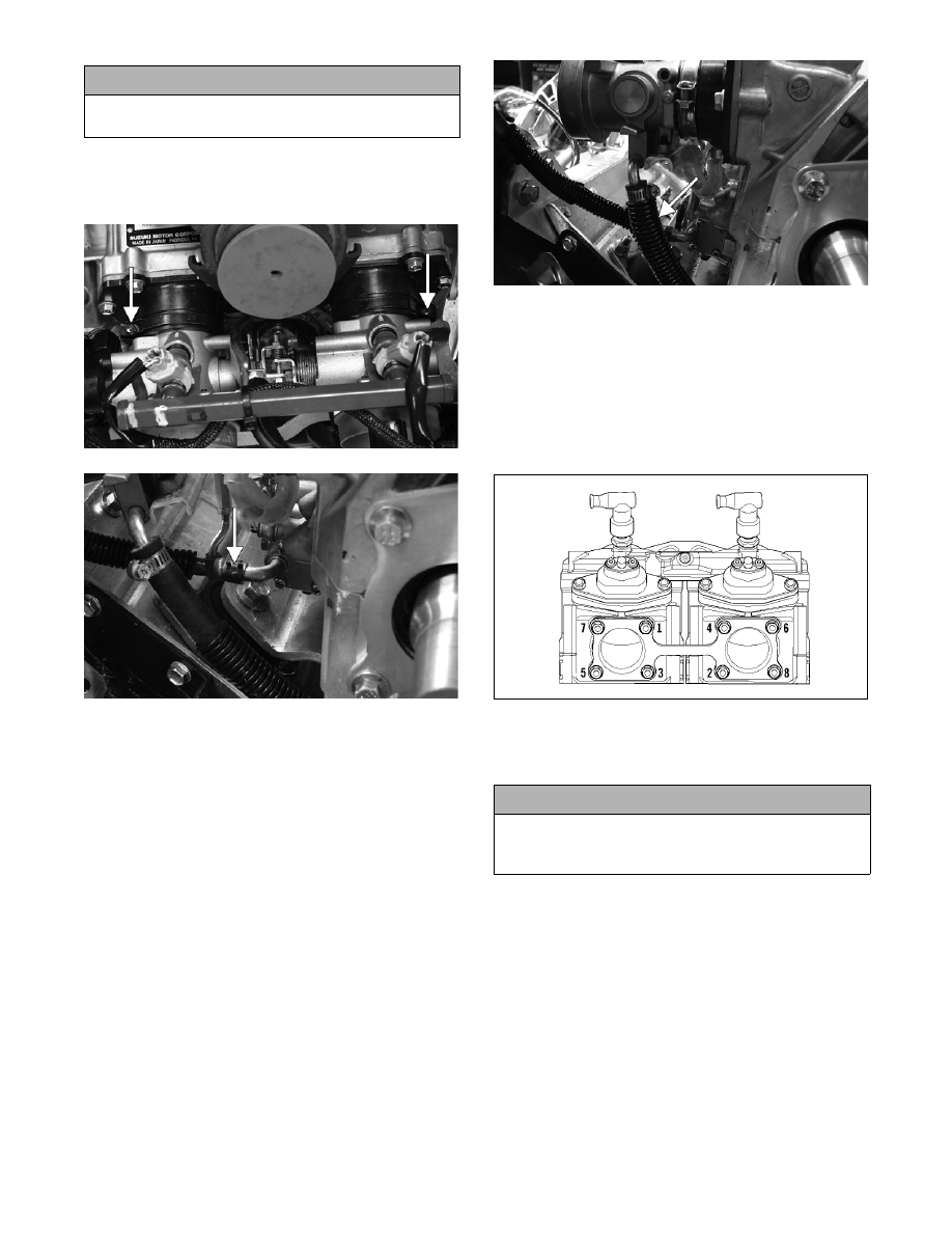
13. Install the throttle body assembly and secure with

the flange clamps; then connect the oil pump con-

trol rod and the oil hose.

FS209A

FS179A

„NOTE: Check to be sure the mark on the control
arm is aligned with alignment mark on the oil-
injection pump boss in the full-open position. If the
marks are not aligned, adjust synchronization by
loosening the jam nuts on the adjuster. Rotate the
jam nuts/adjuster nut until proper alignment is
attained. Tighten jam nuts.

„ NOTE: When the cable/linkage adjusting nut is
adjusted correctly, the throttle lever will move
approximately 3.2 mm (1/8 in.) before the oil-injec-
tion pump arm begins to move.

14. Remove the oil bleed plug from the oil injection

pump. When oil flows from pump free of air bub-

bles and the hose is full of oil, install the oil bleed

plug and tighten.

„NOTE: It is advisable to place a cloth beneath the
oil-injection pump to contain any oil spilled during
the bleeding process.

15. Connect the two throttle body coolant hoses to the

PTO-side and MAG-side throttle body and secure

with the clamps.

FS198A

16. Apply a thin coat of high-temperature silicone

sealant to each exhaust port; then install the

exhaust gaskets.

17. Apply a thin coat of high-temperature silicone

sealant to the mating surfaces of the exhaust mani-

fold; then install the exhaust manifold and secure

with the eight nuts. Using the pattern shown,

tighten to specifications.

0742-292

18. Route the gasline hose to the throttle body assem-

bly and secure the hose to the fuel rail. Tighten the

clamp securely.

19. Connect the coolant overflow hose to the cylinder

head; then connect the spark plug wires to the

spark plugs.

„NOTE: On the 800 cc, connect the knock sensor
wiring to the wiring harness; then secure the con-
nector to the coolant filler neck bracket with the
push-mount cable tie.

! CAUTION

If the bracket/starter motor lock nut was loosened for
installing purposes, tighten the lock nut securely.

! CAUTION

When installing the throttle bodies, make sure the
gasline hose is properly routed to avoid premature
wear and/or contact with exhaust components.

2-175

2

FS212A

„NOTE: At this point, secure the coolant hose,
gasline hose, and on the LXR, the battery cables
together.

FS214A

20. Rotate the servomotor clockwise to remove any

slack from the cables.

21. Slide the APV cable drums into the servomotor

actuator; then place the cable housings into posi-

tion in the servomotor. Secure with the cable

holder and the servomotor retaining clip. Check

APV cable adjustment. See Arctic Power Valve

(APV) System in Section 3.

FS176

FS175

„NOTE: Prior to installing the drive clutch, be sure
to wipe both the crankshaft taper and clutch
mounting taper clean using a clean towel.

22. Place the drive clutch into position on the crank-

shaft and secure with the cap screw and lock

washer. Tighten to specifications.

„NOTE: On the 1000 cc to aid in proper tightening
of the drive clutch cap screw, apply oil to the
threads of the cap screw prior to installing.

23. Install the alignment washers; then install the

driven pulley on the gear case input shaft. Tighten

the cap screw to 4.4 kg-m (32 ft-lb).

FS192

24. Check drive clutch/driven pulley alignment (see

Section 8). Install the drive belt. Check belt deflec-

tion. Secure the belt guard.

! CAUTION

When installing the drive clutch, do not tighten the
clutch cap screw with any kind of impact tool.
Tighten cap screw using a hand torque wrench only.
Failure to do so could result in stationary sheave
damage.

! CAUTION

It is critical that no less than two 1.5 mm (0.060 in.)
washers are in place on the input shaft when install-
ing the driven pulley.

2-176

25. Secure the bearing bracket/steering post assembly

to the upper support plate with the bracket plates

and cap screws (coated with blue Loctite #243).

Tighten the cap screws to 1.1 kg-m (8 ft-lb).

FS182A

„NOTE: When installing the bracket plates, the
wider end of the plate must be directed up.

FS200A

26. Install the air silencer onto the throttle bodies mak-

ing sure the dual intake boot is properly positioned

and seated.

„NOTE: To aid in installing the air silencer, it can
be helpful to remove the air silencer cover and
work the intake boot over the throttle body from
inside the silencer.

FS201A

27. Place the front bumper assembly (with spar pan-

els) into position on the snowmobile; then secure

the front and rear spar panels together with the

torx-head cap screws and lock nuts (A). Tighten

the lock nuts securely.

742-207A

28. Install the body screws and lock nuts (C) from

each side and the self-tapping screws (B) from

each side securing the front bumper assembly to

the chassis. Tighten all hardware securely.

29. Connect the air temperature sensor and place the

sensor harness beneath the air-intake duct; then

install the duct into the silencer.

„NOTE: To aid in installing the duct, it can be help-
ful to apply a thin film of WD-40 to the air silencer
seal and to work the duct back and forth until the
sleeve of the duct is properly seated into the
silencer.

30. Secure the air-intake duct to the upper frame with

the cap screw. Tighten securely.

„NOTE: If the ECU was removed to gain access to
the air-intake duct cap screw, install the ECU using
the two lock nuts. Tighten the lock nuts securely;
then connect the harness plug-ins to the ECU.

FS202A

! CAUTION

Make sure to place the sensor harness beneath the
air-intake duct to avoid contact with exhaust compo-
nents.

2-177

2

31. Using the illustration following step 27, secure the

left-side rear spar panel to the gas tank and support

tube with the three torx-head screws (D). Tighten

the screws securely.

32. Install the seat; then install the machine screw

(threads coated with blue Loctite #243) to the right

side of the seat support.

33. Fill the cooling system (see Liquid Cooling Sys-

tem in Section 3).

34. Place the rubber exhaust bumper into position on

the air silencer.

FS203A

„NOTE: On the LXR, secure the negative battery
cable to the battery.

35. Install the exhaust resonator and secure to the

upper frame with the tab washer and the hairpin

clip.

36. Place gaskets on the resonator and exhaust mani-

fold; then install the expansion chamber. Secure

the chamber to manifold and upper frame with the

springs.

„NOTE: When installing the exhaust manifold
springs, the long hook portion of the spring must
be attached to the exhaust manifold or premature
spring failure will result.

37. Place the console into position on the headlight

support bracket (do not secure the console with the

torx-head screws at this time); then connect the

console/main harness plug-in.

38. Install and close the left-side and right-side access

panels and the hood.

39. Start the engine and warm up to operating temper-

ature; then verify that all components are function-

ing properly and that coolant is circulating through

the cooling system properly.

40. Allow the engine to cool; then check the coolant

level and add coolant as necessary.

41. Verify the tightening torque of the drive clutch.

42. Secure the console to the steering support with the

torx-head screws and tighten the screws securely;

then close the left-side and right-side access panels

and close the hood.

741-722A

! CAUTION

It is critical that machine screw is not installed tight
against the seat support. The screw must be loose
enough to be effective as a seat “stop.”

! CAUTION

Never run the engine with the hood harness discon-
nected or damage to the electrical system will result.

! CAUTION

After running the engine to the proper operating tem-
perature, shut the engine off; then open the hood
and access panels and inspect for any signs of cool-
ant, gasoline, or oil leakage.

! CAUTION

If the engine had a major overhaul or if any major
component was replaced, proper engine break-in
procedures must be followed. If the proper engine
break-in procedures are not followed, severe engine
damage may result.


Content   ..  45  46  47  48   ..