Snowmobile Arctic Cat (2007 year). Manual - part 126


  Index      Snowmobiles / ATV     Snowmobile Arctic Cat - service manual 2007 year


Search            


Content   ..  124  125  126  127   ..


Snowmobile Arctic Cat (2007 year). Manual - part 126


9-119

9

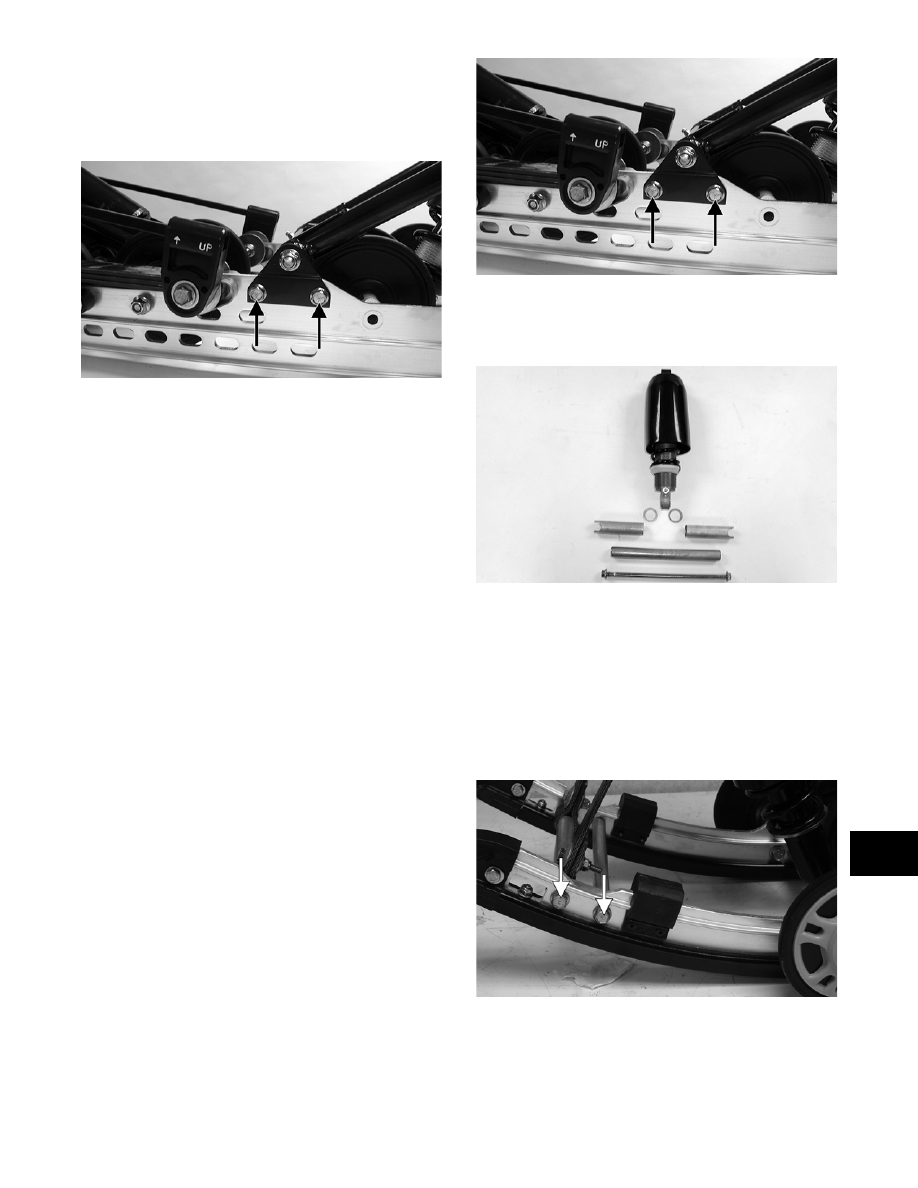
9. Move the rear arm assembly rearward far

enough to gain access to the front arm mounting

bracket lock nuts; then remove the cap screws

and lock nuts securing the brackets to the slide

rails.

MS106A

INSPECTING

„ NOTE: Whenever a part is worn excessively,
cracked, or damaged in any way, replacement is
necessary.

1. Inspect all front arm weldments for cracks or

unusual bends; then inspect the front arm

mounting brackets for cracks and for elongated

holes.

2. Closely inspect all tubing for cracks or unusual

bends.

3. Inspect the bearings, bushings, and front arm

spacers for wear or damage.

4. Inspect the shock absorber for damage and for

any signs of oil leakage especially at the point

where the shock shaft enters the shock body.

5. Inspect the shock absorber eyelet welds (at each

end) for any cracks, signs of separation, or for

unthreading.

INSTALLING

1. Install the front arm mounting brackets to the

slide rails. Secure with cap screws and lock nuts

tightened to specifications.

MS106A

2. Install the axle into the lower shock eyelet bush-

ing assembly; then install the two spacers and

the two shim washers.

MS167

3. Place the front arm shock axle assembly into

position on the skid frame making sure the spac-

ers and washers are properly positioned. Secure

with the cap screw, washer, and a new lock nut.

Tighten to specifications.

„ NOTE: If the front rail support cap screws were
loosened (after step 8), treat the threads with blue
Loctite #243 and tighten to specifications.

ZJ275A

4. Position the front arm with bushings into the

mounting brackets. Secure with cap screws and

lock nuts. Tighten to specifications.

9-120

„ NOTE: Assure that the rear shock pivot is posi-
tioned beneath the front arm prior to securing the
front arm to the mounting brackets.

ZJ272

5. Secure the rear shock pivot to the front arm with

cap screw and lock nut. Tighten to specifica-

tions.

ZJ273

6. Secure the upper shock eyelet and serrated axle

in the mounting hole of the front arm. Secure

with a cap screw and lock nut. Tighten securely.

ZJ271A

„ NOTE: Do not over-tighten the shock absorber
cap screw as the shock eyelet must be free to
pivot.

7. Secure the mounting block on the slide rail with

a cap screw and lock nut. Tighten to specifica-

tions.

MS009

„ NOTE: For proper alignment, it is advisable to
install an idler wheel cap screw into the top mount-
ing block hole prior to tightening.

MS009A

8. Secure the idler wheel assembly with a cap

screw and a lock nut. Tighten cap screws to

specifications.

MS010

9. Secure the limiter straps to the front arm with

cap screws, washers, and lock nuts. Tighten to

specifications.

9-121

9

ZJ270

Rear Shock Absorber 

and Shock Links

„ NOTE: Before removing the skid frame by using
the Rear Suspension Spring Tool (p/n 0144-311),
remove the spring from the adjusting cam.

„ NOTE: The skid frame must be removed for this
procedure (see Removing Skid Frame in this sub-
section).

DISASSEMBLING

1. Using the Rear Suspension Spring Tool (p/n

0144-311), remove the spring from the adjusting

cam.

AG624DA

2. Remove the lock nut and the cap screw securing

the lower shock eyelet and shock links to the

rear shock pivot bracket. Account for shock

sleeves, axle links, and a lock nut.

ZJ277A

„ NOTE: Lay components out in order as they are
removed.

3. Remove the cap screw and lock nut securing the

shock absorber at the upper eyelet and remove

the shock absorber. Account for a sleeve and

bushings.

MS024A

4. Mark the hole that the upper shock links are

mounted in for assembly purposes; then remove

the cap screw and lock nut securing the shock

links to the upper arm bracket. Account for all

mounting hardware.

MS025

! CAUTION

Care must be taken when removing the spring from
the adjusting cam or damage or injury could result.

! WARNING

Care must be taken when removing the spring from
the adjusting cam or damage or injury could result.

9-122

CLEANING AND INSPECTING

„ NOTE: Whenever a part is worn excessively,
cracked, or damaged in any way, replacement is
necessary.

1. Clean shock pivot and idler wheel axle in parts-

cleaning solvent. Dry with compressed air.

2. Clean the idler wheel bearings with a clean

cloth.

3. Closely inspect the idler wheel axle for wear,

bends, or damaged threads at either end.

4. Inspect the idler wheels for signs of cracking,

wear, or outer rubber separation from plastic

wheel.

5. Rotate the idler wheel bearings (by hand) and

inspect for any signs of binding or roughness.

6. If a bearing must be replaced, use this proce-

dure.

A. Remove the bearing snap ring.

B. Using a suitable press, press the bearing out

the inside of the wheel.

C. Press the new bearing (on its outer race) into

the idler wheel.

MS006A

D. Install the snap ring making sure the “sharp

side” is directed away from the bearing.

MS007A

7. Inspect the shock absorber for any signs of oil

leakage especially at the point where the shock

shaft enters the shock body.

8. Inspect the rubber shock bushings located in the

shock absorber eyelets for cracks or deteriora-

tion.

9. Inspect the shock absorber eyelet welds (at each

end) for any cracks or signs of separation.

10. Inspect the welds securing the eyelets of the

shock links for cracks or signs of separation.

Either weld the eyelet or replace the shock link.

11. Inspect the axle surfaces for any signs of corro-

sion. If corrosion is found, lightly buff the sur-

face of the axle with #400 wet-or-dry sandpaper;

then apply a light coat of grease.

ASSEMBLING

1. Secure the shock eyelet to the idler arm with

bushings, sleeve, lock nut, and a cap screw.

Tighten securely.

MS027

2. Secure the rear shock links and the lower shock

absorber eyelet to the shock pivot bracket by

placing the bushings and shock sleeve into the

shock eyelet; then install the axle links into the

rear shock links. Secure the assembly by install-

ing a cap screw through the shock link assem-

bly, shock pivot bracket and shock eyelet

assembly, and shock link assembly. Secure the

assembly with a lock nut. Tighten securely.

! WARNING

Always wear an approved pair of safety glasses
when using compressed air.

! CAUTION

Do not remove the bearing unless it is absolutely
necessary. The bearing will be damaged during
removal.


Content   ..  124  125  126  127   ..