Snowmobile Arctic Cat (2007 year). Manual - part 120


  Index      Snowmobiles / ATV     Snowmobile Arctic Cat - service manual 2007 year


Search            


Content   ..  118  119  120  121   ..


Snowmobile Arctic Cat (2007 year). Manual - part 120


9-95

9

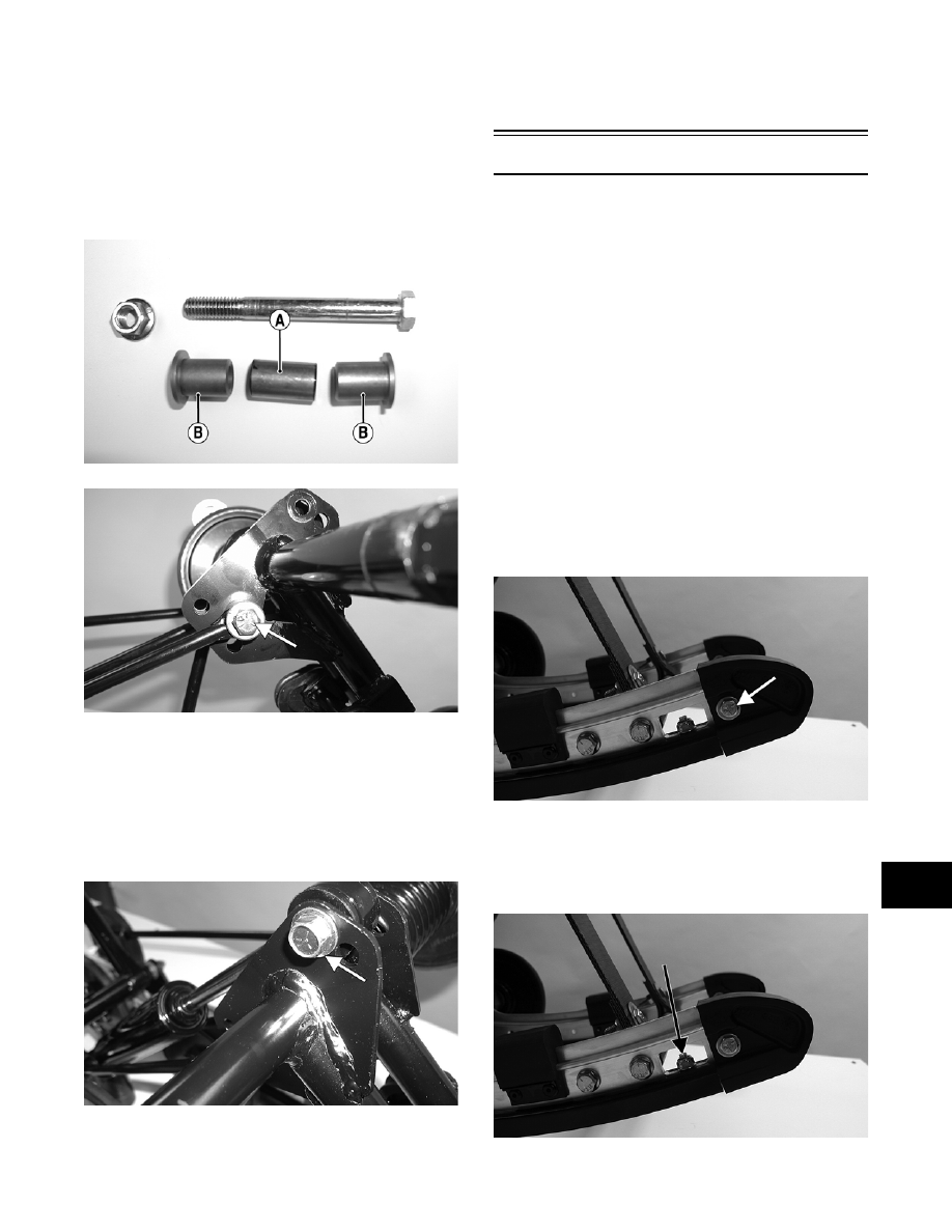
3. Position the shock links in the appropriate holes

of the idler arm brackets (see Chassis and Skid

Frame Mounting Locations in this section).

Place a spacer (A) between the center of the

brackets. Insert the axle links (B) into the upper

shock link eyelets; then insert the cap screw

with washer through the eyelets. Secure with a

cap screw, washer, and lock nut. Tighten

securely.

MS031A

MS048A

4. Install the upper shock absorber eyelet to the

appropriate hole in the idler arm as noted in dis-

assembling.

„ NOTE: Do not over-tighten the shock absorber
cap screw as the shock eyelet must be free to
pivot.

MS024A

5. Install the skid frame (see Installing Skid Frame

in this sub-section).

„ NOTE: It is advisable to install the rear arm
springs onto the adjuster blocks after the skid
frame has been installed.

Slide Rails

„ NOTE: The skid frame must be removed for this
procedure (see Removing Skid Frame in this sub-
section).

REMOVING

„ NOTE: When it is necessary to replace one or
both slide rails, it is recommended that one slide
rail be removed at a time. The remaining slide rail
will then hold the rail supports, axles, and brackets
in their correct assembly order. Always mark the
mounting hole locations during disassembly to
speed up the assembly process and to prevent any
damage. This method is much quicker than to
completely disassemble the entire skid frame. To
replace either rail, use the following procedure.

1. Remove the end cap from the slide rail. Account

for a cap screw, lock nut, and two flat washers.

MS016A

2. Remove the machine screw and lock nut secur-

ing the wear strip to the front of the slide rail;

then using a suitable driving tool, drive the wear

strip rearward off the slide rail.

MS016B

9-96

„ NOTE: If binding of the wear strip occurs, it may
be necessary to use a pipe wrench, start from
either end, and hook the edge of the wear strip
with the pipe wrench jaw and twist the wear strip
off the slide rail. Move the pipe wrench 7.5 cm
(3 in.) and again twist the wear strip off the rail.
Repeat this procedure until the wear strip is free of
the rail.

3. Remove the front arm limiter straps from the

front arm of the skid frame.

MS034A

4. Remove the cap screws securing the two front

rail supports to the slide rail.

MS049A

5. Remove the cap screws and lock nuts securing

the front outer idler wheel and the idler wheel

mounting block.

MS050A

MS003B

6. Account for a flat washer and two spacer wash-

ers.

MS051

7. Remove the cap screw and flat washer securing

the spring slide to the rail. Account for a spacer

and the slide block.

MS052A

„ NOTE: If not already done, remove the short
spring leg from the adjusting cam. Also, it is rec-
ommended that the cap screw be removed from
the front shock absorber to the front arm to aid in
slide rail installing.

8. Remove the lock nut, cap screw, and flat washer

securing the inner idler wheel assembly to the

slide rail. Discard the lock nut.

9-97

9

„ NOTE: If it is necessary to remove the cap
screws from the center components for replacing
the slide rail, install the cap screw from the oppo-
site side into the assembly to secure components
and aid in replacing the slide rail.

MS053A

9. Note the mounting position of the front arm

mounting bracket and remove the cap screws

securing the front arm mounting bracket.

Account for lock nuts.

MS054A

10. Note the mounting location for installing pur-

poses; then remove the cap screw and lock nut

securing the rear inner idler wheels and mount-

ing block.

MS055A

11. Note the mounting positions of the rear arm lim-

iter (A) and rear arm (B); then remove the cap

screws, lock washers, and lock nuts from the

rear arm limiter and rear arm.

MS056A

MS056B

12. Mark the location of the rear coupler block (if

applicable); then remove the block. Account for

the block, bushing, cap screw, and lock nut.

13. Remove the idler wheel insert; then remove the

cap screw and flat washer securing the rear idler

wheel. Remove the idler wheel; then remove the

adjuster bushing.

FC194

9-98

MS057

„ NOTE: The adjusting bolt may have to be loos-
ened to remove the adjuster bushing.

„ NOTE: At this point, the slide rail should be free
of the skid frame components and can be
removed.

14. Remove the cap screws and lock nuts securing

the track adjuster bracket.

MS057A

„ NOTE: The shock pads should be removed only
if being replaced.

15. Using a drill and a 3/16-in. drill bit, drill out the

rivets and remove the shock pads. Note the

shock pad location for installation. Account for

the retaining brackets.

AG528D

INSPECTING

„ NOTE: Whenever a part is worn excessively,
cracked, or damaged in any way, replacement is
necessary.

1. Inspect the slide rail for cracks (A), elongated

holes (B), or unusual bends.

MS220A

2. Inspect the wear strip for wear. The wear strip

must be 10.7 mm (0.42 in.) thick or thicker. If

the wear strip measurement is less than speci-

fied, replacement of both wear strips is neces-

sary.

AG530D

0727-726

INSTALLING

1. Install the shock pads and retaining brackets;

then secure with rivets.


Content   ..  118  119  120  121   ..