Snowmobile Arctic Cat (2007 year). Manual - part 57
7-2
Steering and Body
This section has been organized into sub-sections
for servicing steering and body components; how-
ever, some components may vary from model to
model. The technician should use discretion and
sound judgment when removing and installing com-
ponents.
NOTE: Critical torque specifications are located
on pages 70-71 of this section.
NOTE: Some illustrations and photographs used
in this section are used for clarity purposes only
and are not designed to depict actual conditions.
NOTE: If tipped on its side in excess of a 70°
angle (or upside down at all) without the oil hose
being clamped off, return the snowmobile to the
upright position and immediately see Tipped
Snowmobile (660 cc) sub-section in Section 1 of
this manual for proper procedure to follow.
Steering Post
(120 cc)
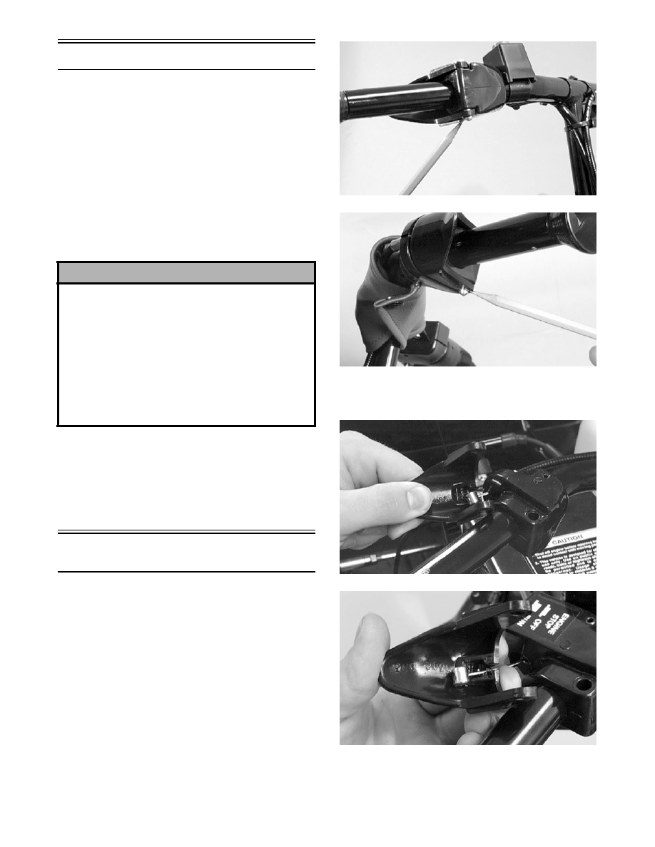
REMOVING
NOTE: Perform steps 1-8 for both the brake and
throttle cables.
1. Remove the handlebar pad.
2. Remove the C-clips securing the brake and
throttle lever pins in the brake housing and
throttle control; then remove the pins and levers.
A979
A998
3. Disconnect the brake and throttle cables from
the levers; then slide the cables out of the levers.
A999
A980
4. Remove the C-clip securing the throttle cable in
the throttle control; then remove the cable from
the throttle control.
! CAUTION
In this section, it will be necessary to tip the 660 cc
snowmobile on its side for accessing some compo-
nents; however, if a 660 cc model must be tipped in
excess of a 70° angle for servicing purposes, use a
suitable clamping device to clamp off the oil hose
next to the valve cover inlet to prevent oil from seep-
ing into the upper engine through the air-intake sys-
tem. Severe engine damage could result if the
engine is run with oil in the upper engine. Care must
be taken to remove the clamping device after servic-
ing.