Snowmobile Arctic Cat (2007 year). Manual - part 17


  Index      Snowmobiles / ATV     Snowmobile Arctic Cat - service manual 2007 year


Search            


Content   ..  15  16  17  18   ..


Snowmobile Arctic Cat (2007 year). Manual - part 17


2-53

2

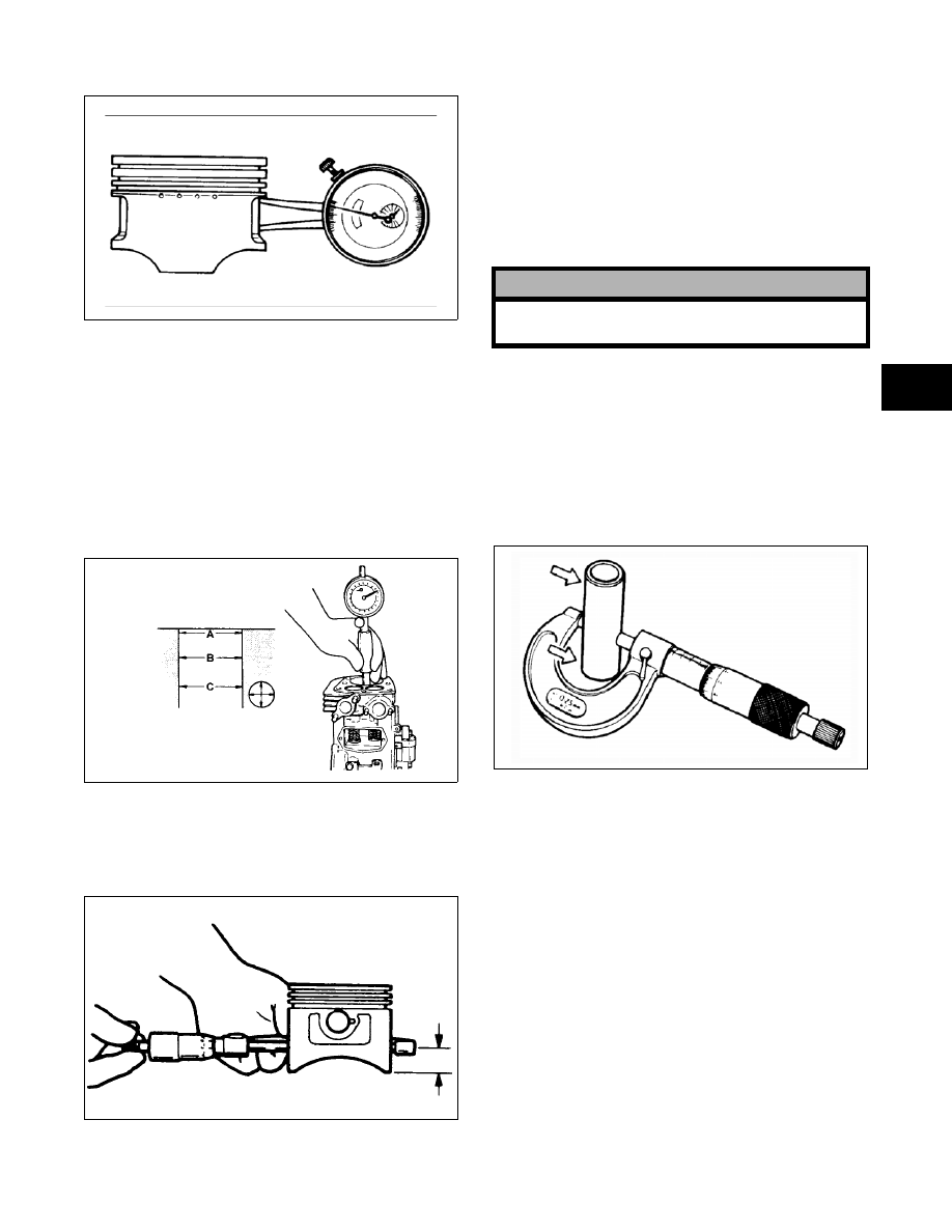
2. Piston pin bore must be within specifications. 

ATV-1069

Measuring Piston Skirt/
Cylinder Clearance

1. Measure the cylinder front to back in six places

using a cylinder bore gauge. The amount of

wear is the difference between the largest and

smallest readings. If the determined wear

exceeds the limit indicated, bore to the next

oversize by using a boring machine or replace

the cylinder.

GEN-0032

2. Measure the corresponding piston diameter at a

point 14 mm (0.551 in.) above the piston skirt at

a right angle to the piston-pin bore. Piston diam-

eter must be within specifications.

GEN-0033

3. Piston skirt to cylinder clearance must be within

specifications.

4. If the piston/cylinder clearance exceeds the

limit, bore the cylinder and use an oversized pis-

ton or replace both cylinder and piston.

Installing Piston Rings

Install the rings in the appropriate grooves. Stagger

the gaps of the rings.

Measuring Piston Pin Diameter

1. Measure the piston pin diameter at each end and

in the center. If measurement is less than mini-

mum specifications, the piston pin must be

replaced.

2. Piston pin diameter must be within specifica-

tions.

ATV-1070

CYLINDER/CYLINDER HEAD

„ NOTE: If the cylinder/cylinder head assembly
cannot be trued, they must be replaced.

Cleaning/Inspecting Cylinder Head

1. Using a non-metallic carbon removal tool,

remove any carbon buildup from the combus-

tion chamber being careful not to nick, scrape,

or damage the combustion chamber or the seal-

ing surface.

2. Inspect the spark plug hole for any damaged

threads. Repair damaged threads using a “heli-

coil” insert.

! CAUTION

Incorrect installation of the piston rings will result in
engine damage.

2-54

3. Place the cylinder head on a surface plate cov-

ered with #400 grit wet-or-dry sandpaper. Using

light pressure, move the cylinder head in a fig-

ure eight motion. Inspect the sealing surface for

any indication of high spots. A high spot can be

noted by a bright metallic finish. Correct any

high spots before assembly by continuing to

move the cylinder head in a figure eight motion

until a uniform bright metallic finish is attained.

Measuring Cylinder Head 

Distortion

1. Remove any carbon buildup in the combustion

chamber.

2. Lay a straightedge across the cylinder head; then

using a feeler gauge, check the distortion factor

between the head and the straightedge.

3. Maximum distortion must not exceed specifica-

tions.

GM130D

Cleaning/Inspecting/Measuring 
Cylinder

1. Wash the cylinder in parts-cleaning solvent.

2. Check the gasket surface of the cylinder for dis-

tortion with a straightedge and thickness gauge

taking a clearance reading at several places. If

the largest reading at any position of the

straightedge exceeds the limit, replace the cylin-

der.

3. Maximum cylinder distortion must not exceed

specifications.

GEN-0030

4. Inspect the cylinder for pitting, scoring, scuff-

ing, warpage, and corrosion. If marks are found,

repair the surface using the Ball Hone (p/n

0644-290) (see Honing Cylinder in this sub-sec-

tion).

5. Place the cylinder on the surface plate covered

with #400 grit wet-or-dry sandpaper. Using light

pressure, move the cylinder in a figure eight

motion. Inspect the sealing surface for any indi-

cation of high spots. A high spot can be noted by

a bright metallic finish. Correct any high spots

before assembly by continuing to move the cyl-

inder in a figure eight motion until a uniform

bright metallic finish is attained.

Honing Cylinder

1. Wash the cylinder in parts-cleaning solvent.

2. Inspect the cylinder for pitting, scoring, scuff-

ing, and corrosion. If marks are found, repair the

surface using the cylinder hone.

„ NOTE: To produce the proper 60° cross-hatch
pattern, use a low RPM drill (600 RPM) at the rate
of 30 strokes per minute. If honing oil is not avail-
able, use a lightweight petroleum-based oil. Thor-
oughly clean cylinder after honing using soap and
hot water. Dry with compressed air; then immedi-
ately apply oil to the cylinder bore. If the bore is
severely damaged or gouged, replace the cylinder.

3. If any cylinder bore measurement exceeds the

limit, hone the cylinder and install an oversized

piston or replace the cylinder.

„ NOTE: Oversized piston and rings are available.
The oversized piston and rings are marked for
identification purposes.

! CAUTION

Water or parts-cleaning solvent must be used in
conjunction with the wet-or-dry sandpaper or dam-
age to the sealing surface may result.

! CAUTION

Water or parts-cleaning solvent must be used in
conjunction with the wet-or-dry sandpaper or dam-
age to the sealing surface may result.

2-55

2

ATV-1068

CAM LOBE WEAR

Worn cam lobes result in reduced power output. The

limit of cam lobe wear is specified for both intake

and exhaust lobes in terms of cam height which is to

be measured with a micrometer. Replace the cam-

shaft if found to be worn below specifications.

Measurement must be within specifications.

GEN0028B

GEN-0029

MEASURING CONNECTING ROD 

SMALL END BORE INSIDE 
DIAMETER 

1. Using a small bore gauge, measure the connect-

ing rod small end bore inside diameter.

2. Measurement must be within specifications. 

GEN-0034

3. If the difference between the connecting rod

small end bore inside diameter and the piston

pin outside diameter exceeds the limit, replace

both connecting rod and piston pin. The mea-

surement must be within specifications.

GEN-0035

CRANKSHAFT RUNOUT

1. Support the crankshaft using a set of V blocks;

use a dial indicator to read crankshaft runout.

„ NOTE: The contact point of the dial indicator
should be on the seal area of the crankshaft.

2. Total indicator reading must not exceed specifi-

cations.

GEN-0031

3. If not within specification, either straighten the

crankshaft or replace it.

2-56

MEASURING CONNECTING ROD 
BIG END SIDE CLEARANCE

1. Check the connecting rod side clearance by

using a thickness gauge. If the clearance

exceeds the limit, replace the connecting rod or

crankshaft.

2. Clearance measurement must be within specifi-

cations.

GEN-0036

MEASURING CRANK PIN/
CONNECTING ROD CLEARANCE

1. Measure the crank pin diameter.

2. Measurement must be within specifications.

GEN-0037

3. Measure the connecting rod big end inside

diameter.

4. Measurement must be within specifications.

GEN-0038

5. Measure the crank pin/connecting rod clearance.

6. Measurement must be within specifications.

GEN-0039

CARBURETOR INSULATOR PLATE

1. Inspect for cracks, scoring, pitting, imperfec-

tions, or warping.

2. Inspect the sealing surfaces for trueness by plac-

ing each on the surface plate covered with #400

grit wet-or-dry sandpaper. Using light pressure,

move both sides in a figure eight motion.

Inspect the sealing surfaces for any indication of

high spots or warping. Correct highs spots by

continuing to move each side in a figure eight

motion. Warped components must be replaced.

A932


Content   ..  15  16  17  18   ..